PL
IA
N
T
Features
*R
oH
S
CO
M
■ Compatible with most surface mount
■
■
■
■
soldering processes
Compatible with popular vacuum pick-and
place equipment
J-hook, gull-wing & pinned configurations
Sealed for board washing
Rated to IP 67 standard
■ Meets EIA/EIAJ/IPC/VRCI SMD standard
outline dimensions
■ Top or side actuated
■ RoHS compliant*
■ For switch applications/processing
guidelines, click here
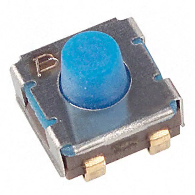
7914 4 mm SMD & Through-hole Sealed Key Switch
Electrical Characteristics
Product Dimensions
Contact Rating
Maximum Current .............. 100 mA max.
Maximum Voltage ............................16 V
Contact Resistance ..... 100 milliohms max.
Insulation Resistance .. 100 megohms min.
Dielectric Strength ........................250 VAC
4.50
(.177)
L
2
1
General Characteristics
Switch Type .........................Normally open
Operating Temperature Range
....................................-55 °C to +125 °C
Storage Temperature Range
....................................-55 °C to +125 °C
Seal Test ...........................85 °C Fluorinert†
Vibration ............................................. 20 G
Shock................................................ 100 G
4.50
(.177)
5.00
(.197)
RECOMMENDED PCB LAYOUT
2.54
(.100)
1.27
(.050)
TYP.
2.54
(.100)
Mechanical Characteristics
- 1
2 +
- 1
2 +
4.93
(.194)
4.50
(.177)
Note: S Style is only available in tape and
reel.
WARNING
Cancer and Reproductive Harm
www.P65Warnings.ca.gov
TYP.
0.76
(.030)
2.54
(.100)
2 PLCS.
5.00 +0.10/-0.15
(.197 +.004/-.006)
4.00
(.157)
RECOMMENDED PCB LAYOUT
2.54
(.100)
0.76
(.030)
TYP.
0.80
(.031)
DIA.
5.00
(.197)
- 1
2
1
4.50
(.177)
1
2.54
(.100)
2.39
DIA.
(.094)
2
5.00
(.197)
0.76 ± 0.10
(.030 ± .004)
TYP.
MM
(INCHES)
2 +
SPST N.O.
RECOMMENDED POLARITY
5.18
(.204)
2.75
(.108)
DIA.
2.38
(.094)
L
2.86
(.113)
0.28 ± 0.20
(.011 ± .008)
6.20
0.60
(.024) (.244)
TYP.
±5° TYP.
0.20 ± 0.08
(.008 ± .003)
RECOMMENDED PCB LAYOUT
2.54
(.100)
1.27
(.050)
TYP.
0.76
(.030)
1
5.44
(.214)
2
0.78
(.031)
2.54
(.100)
3.89
(.153)
0.2 ± 0.13
(.008 ± .005)
0.89
(.035)
1.5
(.059)
RECOMMENDED PCB LAYOUT
0.38 ± 0.2
2.54
(.015 ± .008) (.100)
1.3 TYP.
(.051)
1.25 TYP.
(.049)
1.68
(.066)
5.50
(.216)
1.27
(.050)
TYP.
DIMENSIONS:
5.00
(.197)
2.54
(.100)
2 +
- 1
2.54
2 PLCS.
(.100)
0.13 ± 0.05
(.005 ± .002)
L
5.00
(.197)
Packaging Code (MSL-1)
Blank = Tube (for J, G & H Styles) - 50 pcs.
E = Plastic Embossed Tape & Reel
(for J & G Styles - 500 pcs.)
(for S Style - 200 pcs.)
6.20 ± 0.10
(.244 ± .004)
SPST N.O.
Model
Product Code for Button Height
“L” (For All Styles) from Top of Lid
000 = 1.65 mm
024 = 0.08 mm (Flush)
032 = 0.89 mm
050 = 2.67 mm (available in tube pack only
for J, G & H Styles, tape &
reel only for S Style)
2
1
RECOMMENDED POLARITY
How to Order
Switch Type
1 = N.O. Au Contacts
0.20 ± 0.10
(.008 ± .004)
0.76
TYP.
(.030)
Physical Characteristics
Terminal
J = J-Hook H = Through-hole
G = Gull Wing S = Right Angle
4.50
(.177)
3.81
(.150)
1.78
(.070)
TYP.
Cover Material .....................Stainless steel
Base Material....... Thermoplastic, UL94V-0
Terminal Material ... Copper alloy gold plated
Dome Material .. Stainless steel silver plated
Actuator Material ............ High temperature
silicon rubber
Marking ...................... Manufacturer’s code
and date code
Packaging Options
J & G ................... 500 pcs./reel (MSL-1);
50 pcs./tube
S........................... 200 pcs./reel (MSL-1)
H ......................................... 50 pcs./tube
7914 J - 1 - 000 E
2.17
(.085)
2.39
DIA.
(.094)
5.00
(.197)
Actuator Force ......................... 300 ± 100 g
Pushover Strength (S Style)
........................... 0.9 kilograms minimum
Cycle life, loaded ..........500,000 actuations
Contact resistance ....... 100 milliohms max.
L
5.00 2.39
(.197) (.094)
DIA.
2
1
0.20
(.008)
2
1
5.00
(.197)
4.50
(.177)
2.54
(.100)
1.23
(.048)
TYP.
2.33
(.092)
0.48 ± 0.2
(.019 ± .008)
- 1
2 +
- 1
- 1
2 +
- 1
2 +
2 +
SPST N.O.
SPST N.O.
RECOMMENDED POLARITY
RECOMMENDED POLARITY
±0.3
(.012)
EXCEPT WHERE NOTED.
TOLERANCES:
*RoHS Directive 2002/95/EC Jan. 27, 2003 including annex and RoHS Recast 2011/65/EU June 8, 2011.
†“Fluorinert” is a registered trademark of 3M Co.
Specifications are subject to change without notice. Users should verify actual device performance in their specific
applications. The products described herein and this document are subject to specific legal disclaimers as set forth on the
last page of this document, and at www.bourns.com/docs/legal/disclaimer.pdf.
�7914 4 mm SMD & Through-hole Sealed Key Switch
7914J
7914G
7914S
.35 ± .10
(.014 ± .004)
4.3 ± .10
(.169 ± .004)
.31 ± .10
(.012 ± .004)
4.3 ± .10
(.169 ± .004)
5.50 ± .05
(.217 ± .002)
1.5 + .10/ -.00
DIA.
(.059 + .004/ -.00)
5.50 ± .05
(.217 ± .002)
5.25 ± 0.1
(.207 ± .003)
4.0 ± 0.01
(.158 ± .000)
5.7
(.224)
R
1.6 ± 0.01
(.063 ± .000)
0.4 ± 0.05
(.016 ± .001)
1.5 + .10/ -.00
DIA.
(.059 + .004/ -.00)
5.26 ± .10
(.207 ± .004)
4.00 ± .10
(.157 ± .004)
2.00 ± .05
(.079 ± .002)
6.48 ± .10
(.25 ± .004)
4.00 ± .10
(.157 ± .004)
5.26 ± .10
(.207 ± .004)
5 ° MAX.
4 PLCS.
2.00 ± .05
(.079 ± .002)
35 ° 4 PLCS.
2.45 ± 0.1
(.096 ± .003)
5.26 ± .10
(.207 ± .004)
8.00 .20
(.315 .008)
1.75 ± .10
(.069 ± .004)
12.00 ± .30
(.472 ± .012)
0.3
MAX.
(.011)
1.5
DIA.
(.059)
2.0
(.079)
4.0
(.157)
8.00 ± .20
(.315 ± .008)
1.75 ± .10
(.069 ± .004)
12.00 ± .30
(.472 ± .012)
TAPE
TAPE
1.5
MIN. EQUAL SPACED 3 PLCS.
(.059)
13.0 ± .20
(.512 ± .008) DIA.
1.5
(.059) MIN. EQUAL SPACED 3 PLCS.
13.0 ± .20
DIA.
(.512 ± .008)
20.2
(.795) MIN. DIA.
12.0
(.472)
R
0.3
MAX.
(.011)
1.5 +0.1/-0
(.059 +.001/-.000)
DIA.
1.75
(.069)
20.2
(.795) MIN. DIA.
7.5
(.295)
16.0 ± 0.3
(.630 ± .011)
50.0
MIN.
(1.969)
178 ± 2.0
(7.000 ± .080) DIA.
50.0
(1.969) MIN.
178 ± 2.0
(7.000 ± .080) DIA.
12.4
(.488)
REEL
TAPE
330
MAX. DIA.
(13.0)
12.4
(.488)
REEL
Meets EIA specification 481.
Meets EIA specification 481.
500 pcs./reel
500 pcs./reel
7914J/G
7914H
R .508 TYP
(.020)
R
.508
TYP
(.020)
4.69
(.185)
.508
TYP
(.020)
13º ± 2º 2 PLCS REF
R
5.66 ± .254
(.223 ± .010)
7.67
(.302)
R .762 MAX 2 PLCS
(.030)
4.24
(.167)
DIMENSIONS:
REV. 10/17
8.64 ± .254
(.340 ± .010)
200 pcs./reel
2.82
(.111)
.508 TYP
(.020)
1.78
(.070)
50 pcs./tube
REEL
Meets EIA specification 481.
2.82 2 PLCS
(.111)
60º± 2º
.762
MAX TYP
(.030)
MM
(INCHES)
275
250 ϒC
225
2.54
(.100)
8.89 ± .254
(.350 ± .010)
50 pcs./tube
Specifications are subject to change without notice. Users should verify actual device performance in their
specific applications. The products described herein and this document are subject to specific legal disclaimers as
set forth on the last page of this document, and at www.bourns.com/docs/legal/disclaimer.pdf
Temperature (ϒC)
2.82
(.111)
180 ϒC
175
10-15
Sec.
80-90 Sec.
125 120 ϒC
75
30-40 Sec.
25
0
20
40
60
35-60
Sec.
80 100 120 140 160 180 200
Time (Seconds)
�Legal Disclaimer Notice
This legal disclaimer applies to purchasers and users of Bourns® products manufactured by or on behalf of Bourns, Inc. and
P[Z�HɉSPH[LZ��JVSSLJ[P]LS`��¸)V\YUZ¹��
Unless otherwise expressly indicated in writing, Bourns® products and data sheets relating thereto are subject to change
^P[OV\[�UV[PJL���
很抱歉,暂时无法提供与“7914J-1-024E”相匹配的价格&库存,您可以联系我们找货
免费人工找货- 国内价格 香港价格
- 1+8.110751+1.05131
- 10+6.9362410+0.89907
- 25+6.4553525+0.83674
- 100+5.75629100+0.74613
- 250+5.33267250+0.69122