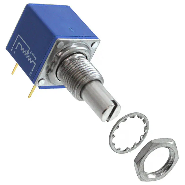
Features
n Compatible with other members of the
Model 80 Series
n The only 10-turn precision potentiometer
in a modular panel control package
n Up to 2 sections available
n RoHS compliant*
Additional Information
Click these links for more information:
PRODUCT
TECHNICAL INVENTORY
LIBRARY
SAMPLES
CONTACT
83/84 – 5/8 ˝ Square 10-Turn Panel Control
Initial Electrical Characteristics1
Wirewound Element (J Taper)
Hybritron® Element (K Taper)
Standard Resistance Range...................................................................200 to 100 K ohms................................................1 K to 100 K ohms
Total Resistance Tolerance......................................................................±5 %......................................................................±10 %
Independent Linearity..............................................................................±0.25 %.................................................................±0.25 %
Absolute Minimum Resistance (J Taper).................................................1.0 ohm or 0.1 % (whichever is greater)...............–
Effective Electrical Angle.........................................................................3600 ° +10 °, -0 °...................................................3600 ° +10 °, -0 °
Dielectric Withstanding Voltage (MIL-STD-202, Method 301)
Sea Level..........................................................................................1,000 VAC minimum.............................................1,000 VAC minimum
Insulation Resistance (500 VDC)............................................................1,000 megohms minimum.....................................1,000 megohms minimum
Power Rating (Voltage Limited By Power Dissipation or 350 VAC, Whichever Is Less)
+70 °C ..............................................................................................1 watt.....................................................................1 watts
+125 °C.............................................................................................0 watt.....................................................................0 watt
Theoretical Resolution.............................................................................See table...............................................................Essentially infinite
End Voltage (K Taper).............................................................................–............................................................................0.2 % of applied voltage
Noise (J Taper)........................................................................................100 ohms ENR maximum.....................................–
Output Smoothness (K Taper).................................................................–............................................................................0.15 % maximum
Environmental Characteristics1
Operating Temperature Range................................................................+1 °C to +125 °C...................................................+1 °C to +125 °C
Storage Temperature Range...................................................................-55 °C to +125 °C..................................................-55 °C to +125 °C
Temperature Coefficient Over Storage Temperature Range...................±50 ppm/°C...........................................................±100 ppm/°C
Vibration..................................................................................................15 G......................................................................15 G
Total Resistance Shift........................................................................±2 %......................................................................±2 %
Voltage Ratio Shift.............................................................................±0.2 %...................................................................±0.2 %
Wiper Bounce....................................................................................0.1 millisecond maximum......................................0.1 millisecond maximum
Shock......................................................................................................50 G......................................................................50 G
Total Resistance Shift........................................................................±2 %......................................................................±2 %
Voltage Ratio Shift.............................................................................±0.2 %...................................................................±0.2 %
Wiper Bounce....................................................................................0.1 millisecond maximum......................................0.1 millisecond maximum
Load Life..................................................................................................1,000 hours...........................................................1,000 hours
Total Resistance Shift........................................................................±2 % maximum.....................................................±5 % maximum
Rotational Life (No Load)........................................................................1,000,000 shaft revolutions...................................4,000,000 shaft revolutions
Total Resistance Shift........................................................................±5 % maximum ....................................................±5 % maximum
Moisture Resistance (MIL-STD-202, Method 103, Condition B)
Total Resistance Shift........................................................................±2 % maximum.....................................................±5 % maximum
Insulation Resistance (500 VDC)......................................................100 megohms minimum........................................100 megohms minimum
IP Rating..................................................................................................IP 40......................................................................IP 40
Mechanical Characteristics1
Stop Strength�������������������������������������������������������������������������������������������������������������������������������������������������������������������� 33.90 N-cm (48.0 oz.-in.) minimum
Mechanical Angle������������������������������������������������������������������������������������������������������������������������������������������������������������������������������������������3600 ° +15 °, -0 °
Torque
Starting��������������������������������������������������������������������������������������������������������������������������������������������Running torque plus 0.7 N-cm (1.0 oz.-in.) maximum
Running (1 or 2 Section)�����������������������������������������������������������������������������������������������������������������������������������������0.18 to 1.41 N-cm (0.25 to 2.0 oz.-in.)
Mounting (Torque on Bushing)��������������������������������������������������������������������������������������������������������������������������������� 1.7-2.0 N-m (15-18 lb.-in.) maximum
Shaft Runout������������������������������������������������������������������������������������������������������������������������������������������������������������������������������������0.15 mm (0.006 in.) T.I.R.
Shaft End Play����������������������������������������������������������������������������������������������������������������������������������������������������������������������������������0.36 mm (0.014 in.) T.I.R.
Shaft Radial Play������������������������������������������������������������������������������������������������������������������������������������������������������������������������������0.13 mm (0.005 in.) T.I.R.
Weight (Single Section)���������������������������������������������������������������������������������������������������������������������������������������������������������������������������������� 21 gm (0.75 oz.)
(Each Additional Section)������������������������������������������������������������������������������������������������������������������������������������������������������������������������� 18 gm (0.65 oz.)
Terminals���������������������������������������������������������������������������������������������������������������������������������������������������������������������� Printed circuit terminals or solder lugs
Soldering Condition������������������������������������������������������������������� Recommended hand soldering using Sn95/Ag5 no clean solder, 0.025 ˝ wire diameter.
.
Maximum temperature 399 °C (750 °F) for 3 seconds. No wash process to be used with no clean flux
Marking��������������������������������������������������������������������������Manufacturer’s trademark, wiring diagram, date code and resistance, manufacturer’s part number.
Ganging (Multiple Section Potentiometers)����������������������������������������������������������������������������������������������������������������������������������������������������� 2 cup maximum
Hardware������������������������������������������������������������������� One lockwasher and one mounting nut is shipped with each potentiometer; locking bushing versions
are shipped with one additional locking nut (Bushing A: H-37-2 & H-38-2; Bushing B: H-37-2, H-38-2 & H-38-4; Bushing C: H-37-1 & H-38-1;
Bushing E: H-37-1, H-38-1 & H-38-3; Bushing J: H-37-2 & H-38-2; Bushing N: H-37-1 & H-38-1; Bushing R: H-37-4 & H-38-9;
Bushing U: H-37-3 & H-38-8)
NOTE: Model 83/84 performance specifications do not apply to units subjected to printed circuit board cleaning procedures.
1Electrical specifications tested at 250 RPM, at room ambient: +25 °C nominal.
WARNING
Cancer and Reproductive Harm
www.P65Warnings.ca.gov
*RoHS Directive 2015/863, Mar 31, 2015 and Annex.
Specifications are subject to change without notice. Users should verify actual device performance in their specific
applications. The products described herein and this document are subject to specific legal disclaimers as set forth on the
last page of this document, and at www.bourns.com/docs/legal/disclaimer.pdf.
�Dual Section Model 83 PC Pins
37.03 ± .71
(1.458 ± .028)
83/84 – 5/8 ˝ Square 10-Turn Panel
7.62 ± .25Control
(.30 ± .01)
Dimensional Drawings
Wirewound Resolution Table
Resistance Resolution
(Ohms)
(Nom.) (%)
200
.048
500
.037
1 K
.032
2 K
.031
5 K
.023
10 K
.020
20 K
.015
50 K
.012
100 K
.010
Dual Section Model 84 Solder Lugs
Dual Section Model 83 PC Pins
37.03 ± .71
(1.458 ± .028)
37.03 ± .71
(1.458 ± .028)
7.62 ± .25
(.30 ± .01)
7.62 ± .25
(.30 ± .01)
Note: The Models 83/84 dimensions for dual
section assembly are for either single or dual
concentric shaft styles.
DIMENSIONS:
MM
(INCHES)
Dual Section Model 84 Solder Lugs
37.03 ± .71
(1.458 ± .028)
Suggested Panel Layout
B
BUSHING
C
D
E
A
DIM A
A, B & J
9.91
(.39)
C, E & N
ANTI-ROTATION LUG
DIM B
A
7.75
(.305)
6.73
(.265)
B
7.75
(.305)
R&S
10.5
(.413)
C
N/A
U
7.5
(.295)
E
13.49
(.531)
F
J
DIMENSIONS:
MM
(INCHES)
DIM C
DIM D
N/A
N/A
2.49
(.098)
7.75
7.62 ± .25
(.305)
N/A
2.49
(.098)
(.30 ± .01)
7.75
DIM E
2.49
Note: The Models 83/84
dimensions for dual
N/A
(.305)
section
assembly are for either single or(.098)
dual
concentric shaft styles.
N/A
N/A
3.45
(.136)
N/A
N/A
7.75
(.305)
2.54
(.100)
9.53
(.375)
N/A
N/A
2.54
(.100)
Date Code Description
YYWWM
M = COUNTRY OF MANUFACTURE
(MEXICO)
WW = WEEK NUMBER
YY = LAST TWO DIGITS OF YEAR
MANUFACTURED
Specifications are subject to change without notice.
Users should verify actual device performance in their specific applications.
The products described herein and this document are subject to specific legal disclaimers as set forth on the last page of this document, and at www.bourns.com/docs/legal/disclaimer.pdf.
�
83/84 – 5/8 ˝ Square 10-Turn Panel Control
Product Dimensions
PC Pin Model 83
15.88 ± .38
(.625 ± .015)
19.05 ± .51
(.75 ± .02)
.79 ± .41
(.031 ± .016)
15.88 ± .38
(.625 ± .015)
1.52
(.06)
6.10 ± .51
(FMS TO C )
L
(.24 ± .02)
6.35 ± 1.02
(.25 ± .04)
.30
(.012) TYP. 3 PLCS.
2.54 ± .25
(.10 ± .01)
.91
(.036)
7.62 ± .25
(.30 ± .01)
Solder Lug Model 84
15.88 ± .38
(.625 ± .015)
6.79 ± .41
(.031 ± .01)
5.59 ± .51
(.22 ± .02)
2.54 ± .25
(.10 ± .01)
9.50 ± 0.40
(.375 ± .15)
1
3
WIPER
3
1
CW
CLOCKWISE
Shaft Flat Orientation
1.60 + .38/-.00 DEEP
7.92
(.063+.015/-.000)
(.312)
.25
MIN. 9.53 ± .13
45 ° ± 5 ° X (.010)
(.375 ± .005)
CHAMFER
PILOT DIA.
5.49 OPTIONAL FLAT 16.00 LONG OR 1.52 FROM
(.63)
(.216
)
17.66 (.06)
A" BUSHING END FOR SHAFTS UNDER (11/16)
"B" Bushing
3/8 " (9.53 mm) Dia. Plain - Single Shaft
120 ° ± 5 °
STD. FLAT
ORIENTATION
(SHAFT AT
CCW END)
2.31
(.091)
E
3.18
(.125)
6.32 ± .03
DIA.
(.249 ± .001)
9.53 ± .13
(.375 ± .005)
PILOT DIA.
Locating Lug Options - All Model 80 Series
7.75
(.305)
SHAFT SLOT 1.19 WIDE X
(.047)
1.60 + .38/-.00 DEEP
(.063 + .015/-.000)
11.13
(.438)
MIN.
3/8-32 UNEF
J
13.50
(.531)
2.36
(.093)
.25
45 ° ± 5 ° X (.010)
CHAMFER
H
9.53
(.375)
11.10
(.437)
3.18
(.125)
15.90 ± 0.80
(5/8 ± 1/32)
STANDARD
3.162 ± .025
DIA.
(.1245 ± .001)
6.35 ± .13
(.500 ± .005)
1/4-32 UNEF
10.80
(.425)
MIN.
6.35 ± .05
(.250 ± .002)
PILOT DIA.
SHAFT SLOT
.78
.78 .25
WIDE X
±
DEEP
(.031)
(.031) (.010)
.25
45 ° ± 5 ° X (.010)
CHAMFER
"A" Bushing
3/8 " (9.53 mm) Dia. Plain - Concentric Shaft
19.05 ± .79
(3/4 ± 1/32)
STANDARD
28.58 ± .79
(1.125 ± .031)
STANDARD
9.53
(.375)
3.162 ± .025
DIA.
(.1245 ± .001)
6.32 ± .03
(.249 ± .001)
1.98 ± .03
DIA.
(.078 ± .001)
DIA.
TRIPLE CONCENTRIC
(SPECIAL ORDER)
3/8-32 UNEF
6.32
3.18
OUTER SHAFT
DIA. OPERATES SECTION #1 INNER SHAFT
(.249)
(.125)
DIA. OPERATES SECTION #2, #3, & #4 ("G" STYLE)
"C" Bushing
1/4 " (6.35 mm) Dia. Plain - Concentric Shaft
15.88 ± .79
(5/8 ± 1/32)
STANDARD
12.70 ± .13
(.500 ± .005)
NOTE: SLOTTED
END SHAFT
ORIENTATION IS
RANDOM.
.46
(.018)
12.7,15.88,19.05,22.23± .79
(1/2, 5/8, 3/4, 7/8 ± 1/32)
STANDARD
6.32 ± .03
DIA.
(.249 ± .001)
SHAFT SLOT 1.19 WIDE X
(.047)
2
A
3/8-32 UNEF
"E" Bushing
1/4 " (6.35 mm) Dia. Locking - Single Shaft
2.03 ± .13
1.78 ± .25 (.080 ± .005)
(.070 ± .010)
3.56
(.14)
"A" Bushing
3/8 " (9.53 mm) Dia. Plain - Single Shaft
2
CCW
1.52
(.06)
6.10 ± .51
(FMS TO C )
L
(.24 ± .02)
SLOT
1.02 WIDE X 2.29 LONG
.30
(.090)
TYP. 3 PLCS.
(.040)
(.012)
TYP.
7.62 ± .25
9.14 ± .76
(.30 ± .01)
(.360 ± .03)
SHAFT SLOT
.79 WIDE X .79
(.031)
(.031)
.25
±.25 DEEP
6.35 ± .05 45 ° ± 5 ° X
(.010)
(.250 ± .002) CHAMFER
(±.010)
PILOT DIA.
2.39
OPTIONAL FLAT 6.35 LONG OR 1.52 FROM
(.250)
(.094)
(.06)
14.30
"C" BUSHING END FOR SHAFTS UNDER (9/16)
15.88 ± .38
(.625 ± .015)
19.05 ± .51
(.75 ± .02)
9.53,12.7,15.88,19.05,22.23 ± .79
(3/8, 1/2, 5/8, 3/4, 7/8, ± 1/32)
STANDARD
3.162 ± .025
DIA.
(.1245 ± .001)
6.35 ± .13
(.250 ± .005)
4.45
(.175)
MIN.
5.08 ± .51
(.20 ± .02)
9.14 ± .76
(.36 ± .03)
"C" Bushing
1/4 " (6.35 mm) Dia. Plain - Single Shaft
.79 ± .41
(.031 ± .016)
15.88 ± .79
(5/8 ± 1/32)
STANDARD
6.35
(.25)
25.40 ± .79
(1 ± 1/32)
STANDARD
1.98 ± .03
DIA.
(.078 ± .001)
3.162 ± .025
DIA.
(1.245 ±.0010)
1/4-32 UNEF
3.18
OUTER SHAFT
DIA.OPERATES SECTION #1 INNER SHAFT
(.125)
1.98
(.08) DIA. OPERATES SECTION #2, #3, & #4 ("K" STYLE)
TOLERANCES EXCEPT AS SHOWN: DECIMALS .XXX ± .127
(.005)
.XX± .38
(.015)
ANGLE ± 5 °
FRACTIONS ± 1/64
DIMENSIONS:
MM
(INCHES)
NOTE: "D" OPTION - NO A/R LUG. OTHER LOCATING LUG OPTIONS AVAILABLE. FOR DETAILS CONSULT FACTORY.
Specifications are subject to change without notice.
Users should verify actual device performance in their specific applications.
The products described herein and this document are subject to specific legal disclaimers as set forth on the last page of this document, and at www.bourns.com/docs/legal/disclaimer.pdf.
�
83/84 – 5/8 ˝ Square 10-Turn Panel Control
Hardware
LOCKWASHER H-37-1
NUT H-38-1
6.6
(.26)
LOCKNUT H-38-3
9.53 +0/-0.38
(.375 +0/-.015)
2.36 ± 0.25
(.093 ± .01)
1/4-32 UNEF
12.07 ± 0.25
(.475 ± .01)
0.64 ± 0.05
(.025 ± .002)
LOCKWASHER H-37-2
4.57 ± 0.05
(.180 ± .002)
15 ° ± 1 °
7.75
(.305)
30 ° ± 5 °
TYP.
11 +0/-0.43
(.433 +0/-.017)
1/4-32
NEF-20
0.64
(.025)
7.92
(.312)
NUT H-38-2
9.58 ± 0.36
(.377 ± .014)
2.36 ± 0.25
(.093 ± .01)
1.02
(.040)
30 ° ± 5 °
3/8-32 NEF-2B
12.52 ± 0.36
(.493 ± .014)
0.56 ± 0.05
(.022 ± .002)
LOCKWASHER H-37-3
30 ° ± 5 °
14.66 +0/-0.43
(.577 +0/-.017)
NUT H-38-8
7.24 ± 0.38
(.285 ± .015)
LOCKNUT H-38-4
10 ± 0.2
(.394 ± .008)
2 ± 0.2
(.079 ± .008)
M7 x .75
12.45 ± 0.38
(.490 ± .015)
0.71 ± 0.18
(.028 ± .007)
LOCKWASHER H-37-4
18 ° ± 2 °
3/8-32
NEF-2B
1.02
(.040)
12.7
(.5)
14 ± 0.2
(.551 ± .008)
30 ° ± 5 ° TYP.
0.56 ± 0.05
(.022 ± .002)
4.83
(.19)
30 ° ± 15 °
TYP.
DIMENSIONS:
1.14 ± 0.38
(.045 ± .015)
2.9 ± 0.2
(.114 ± .008)
M10 x .75
15.11 ± 0.51
(.595 ± .020)
1.91
MIN.
(.075)
8.51 ± 0.05
(.335 ± .002)
30 ° ± 15 °
TYP.
NUT H-38-9
10.41 ± 0.38
(.410 ± .015)
3.96
(.156)
MM
(INCHES)
LOCKNUT H-38-10
1.91
MIN.
(.075)
8.76 ± 0.13
(.345 ± .005)
18 ° ± 2 °
M10
x 0.75
1.02
(.040)
14 ± 0.25
(.551 ± .01)
Asia-Pacific: Tel: +886-2 2562-4117
Email: asiacus@bourns.com
EMEA: Tel: +36 88 885 877
Email: eurocus@bourns.com
The Americas: Tel: +1-951 781-5500
Email: americus@bourns.com
www.bourns.com
1.14 ± 0.38
(.045 ± .015)
30 ° ± 5 ° TYP.
5 ± 0.25
(.197 ± .01)
Specifications are subject to change without notice.
Users should verify actual device performance in their specific applications.
The products described herein and this document are subject to specific legal disclaimers as set forth on the last page of this document, and at www.bourns.com/docs/legal/disclaimer.pdf.
�
83/84 – 5/8 ˝ Square 10-Turn Panel Control
How To Order
83
A
1
A
-
B
28
-
J
15
L
RoHS IDENTIFIER
L
Compliant
A
B
C
D
E
F
J
ANTI-ROTATION LUG
Single .305 R, 90 °CW
Double .305 R, 90 ° & 270 °CW
Single .305 R, 270 °CW
No Lug
Single .531 R, 90 °CW
Single .305 R, 180 °CW
Single .375 R, 90 °CW
SHAFT
AVAILABLE
LENGTH
ONLY IN
(FMS)
BUSHING
Code Description
Code
12
3/8 ” L
C, N, J
16
1/2 ” L
A, C, J, N
20
5/8 ” L
A, B, C, E, J, N
24
3/4 ” L
A, B, C, E, J, N
28
7/8 ” L
A, B, C, E, J, N
32
1”L
A, B, C, E, J, N
36
1-1/8 ” L
A, B, C, E, J, N
40
1-1/4 ” L
A, B, C, E, J, N
Metric
10
10 mmL
U
13
13 mmL
U
16
16 mmL
R
19
19 mmL
R
22
22 mmL
R, U
30
30 mmL
R
42
42 mmL
R
50
50 mmL
R
# SECTIONS
1 Single
2 Double
3 Triple
A
B
C
E
J
N
R
U
83
84
BUSHING
Plain 3/8 ” (9.53 mm) D x 3/8 ” (9.53 mm) L
Locking 3/8 ” (9.53 mm) D x 1/2 ” (12.7 mm) L
Plain 1/4 ” (6.35 mm) D x 1/4 ” (6.35 mm) L
Locking 1/4 ” (6.35 mm) D x 1/2 ” (12.7 mm) L
Plain 3/8 ” (9.53 mm) D x 1/4 ” (6.35 mm) L
Plain 1/4 ” (6.35 mm) D x 3/8 ” (9.53 mm) L
Plain 10 mm D x 9 mm L
Plain 7 mm D x 6 mm L
K
L
M
N
P
R
T
V
(J)
(K)
Linear Wirewound
10-Turn ±5 %
Linear Hybritron®
Elements 10-Turn ±10 %
RESISTANCE CODE
VALUE IN OHMS
J
K
(06) - 200
(10) - 1 K
(08) - 500
(11) - 2 K
(10) - 1 K
(13) - 5 K
(11) - 2 K
(15) - 10 K
(13) - 5 K
(16) - 20 K
(15) - 10 K (18) - 50 K
(16) - 20 K (20) - 100 K
(18) - 50 K
(20) - 100 K
MODEL
10-Turn, PC Pins
10-Turn, Solder Lugs
SHAFT TYPE
A
B
C
E
F
G
ELEMENT TAPER
TYPE/TOLERANCE
Single Plain 1/4 ” (6.35 mm) D
Single Slotted 1/4 ” (6.35 mm) D
Single Flatted 1/4 ” (6.35 mm) D
Single Slotted 1/8 ” (3.18 mm) D
Single Flatted 1/8 ” (3.18 mm) D
Dual Concentric Plain 1/4 ” (6.35 mm) D - 1/8 ” (3.18 mm) D
Outer Operates Section 1
Dual Concentric Plain 1/8 ” (3.18 mm) D - 5/64 ” (1.98 mm) D
Outer Operates Section 1
Dual Concentric Plain 1/4 ” (6.35 mm) D - 1/8 ” (3.18 mm) D
Outer Operates Section 1/2
Dual Concentric Plain 1/8 ” (3.18 mm) D - 5/64 ” (1.98 mm) D
Outer Operates Section 1
Dual Concentric Plain 1/4 ” (6.35 mm) D - 1/8 ” (3.18 mm) D
Outer Operates Section 1/2/3
Dual Concentric Plain 1/8 ” (3.18 mm) D - 5/64 ” (1.98 mm) D
Outer Operates Section 1/2
Single Slotted 6 mm D
Single Slotted 4 mm D
Dual Concentric Plain 6 mm D - 3 mm D
Outer Operates Section 1
AVAILABLE ONLY IN
LENGTHS
BUSHINGS
(CODE)
(CODE)
16,20,24,28
A, B, J
16,20,24,28
A, B, J
20,24,28
A, B, J
12,16,20,24,28 C, E, N
Consult Factory C, N
36,40
A, J
32,36
C, N
36,40
A, J
32,36
C, N
36,40
A, J
32,36
C, N
16,19,22,50
10, 13, 22
30, 42
R, S
U
R
Boldface features are Bourns standard options.
All others are available with higher minimum order
quantities.
REV. 03/22
Specifications are subject to change without notice.
Users should verify actual device performance in their specific applications.
The products described herein and this document are subject to specific legal disclaimers as set forth on the last page of this document, and at www.bourns.com/docs/legal/disclaimer.pdf.
�
Legal Disclaimer Notice
This legal disclaimer applies to purchasers and users of Bourns® products manufactured by or on behalf of Bourns, Inc. and its
affiliates (collectively, “Bourns”).
Unless otherwise expressly indicated in writing, Bourns® products and data sheets relating thereto are subject to change
without notice. Users should check for and obtain the latest relevant information and verify that such information is current and
complete before placing orders for Bourns® products.
The characteristics and parameters of a Bourns® product set forth in its data sheet are based on laboratory conditions, and
statements regarding the suitability of products for certain types of applications are based on Bourns’ knowledge of typical
requirements in generic applications. The characteristics and parameters of a Bourns® product in a user application may vary
from the data sheet characteristics and parameters due to (i) the combination of the Bourns® product with other components
in the user’s application, or (ii) the environment of the user application itself. The characteristics and parameters of a Bourns®
product also can and do vary in different applications and actual performance may vary over time. Users should always verify
the actual performance of the Bourns® product in their specific devices and applications, and make their own independent
judgments regarding the amount of additional test margin to design into their device or application to compensate for
differences between laboratory and real world conditions.
Unless Bourns has explicitly designated an individual Bourns® product as meeting the requirements of a particular industry
standard (e.g., ISO/TS 16949) or a particular qualification (e.g., UL listed or recognized), Bourns is not responsible for any
failure of an individual Bourns® product to meet the requirements of such industry standard or particular qualification. Users of
Bourns® products are responsible for ensuring compliance with safety-related requirements and standards applicable to their
devices or applications.
Bourns® products are not recommended, authorized or intended for use in nuclear, lifesaving, life-critical or life-sustaining applications, nor in any other applications where failure or malfunction may result in personal injury, death, or severe property or
environmental damage. Unless expressly and specifically approved in writing by two authorized Bourns representatives on a
case-by-case basis, use of any Bourns® products in such unauthorized applications might not be safe and thus is at the user’s
sole risk. Life-critical applications include devices identified by the U.S. Food and Drug Administration as Class III devices and
generally equivalent classifications outside of the United States.
Bourns expressly identifies those Bourns® standard products that are suitable for use in automotive applications on such
products’ data sheets in the section entitled “Applications.” Unless expressly and specifically approved in writing by two
authorized Bourns representatives on a case-by-case basis, use of any other Bourns® standard products in an automotive
application might not be safe and thus is not recommended, authorized or intended and is at the user’s sole risk. If Bourns
expressly identifies a sub-category of automotive application in the data sheet for its standard products (such as infotainment
or lighting), such identification means that Bourns has reviewed its standard product and has determined that if such Bourns®
standard product is considered for potential use in automotive applications, it should only be used in such sub-category of
automotive applications. Any reference to Bourns® standard product in the data sheet as compliant with the AEC-Q standard
or “automotive grade” does not by itself mean that Bourns has approved such product for use in an automotive application.
Bourns® standard products are not tested to comply with United States Federal Aviation Administration standards generally
or any other generally equivalent governmental organization standard applicable to products designed or manufactured for
use in aircraft or space applications. Bourns expressly identifies Bourns® standard products that are suitable for use in aircraft
or space applications on such products’ data sheets in the section entitled “Applications.” Unless expressly and specifically
approved in writing by two authorized Bourns representatives on a case-by-case basis, use of any other Bourns® standard
product in an aircraft or space application might not be safe and thus is not recommended, authorized or intended and is at the
user’s sole risk.
The use and level of testing applicable to Bourns® custom products shall be negotiated on a case-by-case basis by Bourns and
the user for which such Bourns® custom products are specially designed. Absent a written agreement between Bourns and the
user regarding the use and level of such testing, the above provisions applicable to Bourns® standard products shall also apply
to such Bourns® custom products.
Users shall not sell, transfer, export or re-export any Bourns® products or technology for use in activities which involve the
design, development, production, use or stockpiling of nuclear, chemical or biological weapons or missiles, nor shall they use
Bourns® products or technology in any facility which engages in activities relating to such devices. The foregoing restrictions
apply to all uses and applications that violate national or international prohibitions, including embargos or international
regulations. Further, Bourns® products and Bourns technology and technical data may not under any circumstance be
exported or re-exported to countries subject to international sanctions or embargoes. Bourns® products may not, without prior
authorization from Bourns and/or the U.S. Government, be resold, transferred, or re-exported to any party not eligible
to receive U.S. commodities, software, and technical data.
To the maximum extent permitted by applicable law, Bourns disclaims (i) any and all liability for special, punitive, consequential,
incidental or indirect damages or lost revenues or lost profits, and (ii) any and all implied warranties, including implied warranties
of fitness for particular purpose, non-infringement and merchantability.
For your convenience, copies of this Legal Disclaimer Notice with German, Spanish, Japanese, Traditional Chinese and Simplified Chinese
bilingual versions are available at:
Web Page: http://www.bourns.com/legal/disclaimers-terms-and-policies
PDF: http://www.bourns.com/docs/Legal/disclaimer.pdf
C1753 05/17/18R
�