Features
n Available in a variety of pin-out
configurations
n Virtually infinite electrical circuit isolation
n Metal or plastic shaft options
n RoHS compliant*
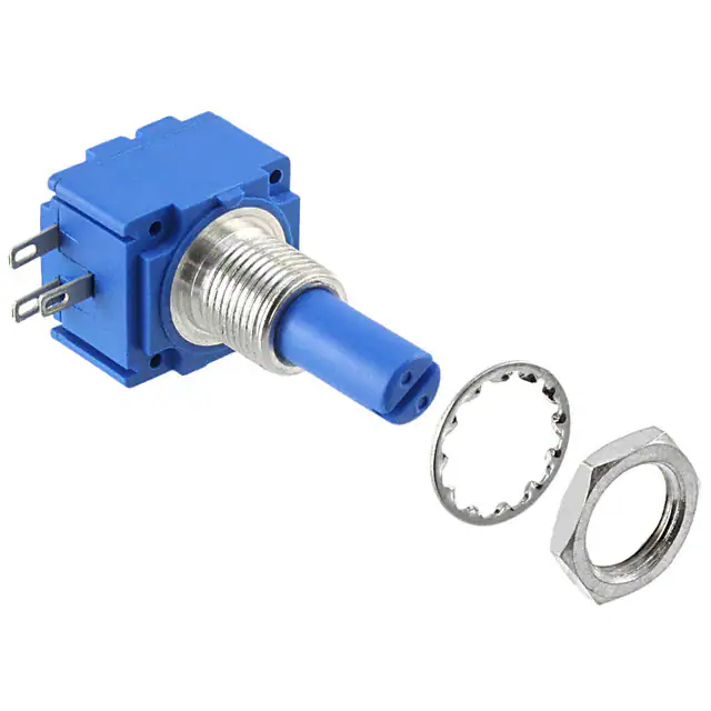
Model 91, 92, 93, 94 & 95 – 5/8 ˝ Square Single-Turn Panel Control
Initial Electrical Characteristics1
Conductive Plastic Element
Cermet Element
Standard Resistance Range
Linear Tapers (A, B, E, & H).........................(B & E) 1 K ohms to 1 megohm.........................(A & H) 100 ohms to 1 megohm
Audio Tapers (C, D, F, G, S, & T).................(D,G,S, & T) 1 K ohms to 1 megohm................(C & F) 1 K ohms to 1 megohm
Total Resistance Tolerance................................10 % or 20 %.....................................................5% or 10%
Independent Linearity........................................±5 %..................................................................±5 %
Absolute Minimum Resistance..........................2 ohms maximum.............................................. 2 ohms maximum
Effective Electrical Angle...................................(Linear tapers) 240 ° ± 5 °.................................(Linear tapers) 240 ° ± 6 °
(Audio tapers) 225 ° ± 5 °..................................(Audio tapers) 225 ° ± 6 °
Contact Resistance Variation............................±1 %..................................................................±1 % or 3 ohms (whichever is greater)
Dielectric Withstanding Voltage (MIL-STD-202, Method 301)
Sea Level.....................................................1,500 VAC minimum..........................................1,500 VAC minimum
70,000 Feet..................................................500 VAC minimum.............................................500 VAC minimum
Insulation Resistance (500 VDC)......................1,000 megohms minimum.................................1,000 megohms minimum
Power Rating (Voltage Limited By Power Dissipation or 350 VAC, Whichever Is Less)
+70 °C Single Section Assembly.................(Linear tapers) 1 watt........................................(Linear tapers) 2 watts
(Audio tapers) 0.5 watt......................................(Audio tapers) 1 watt
+70 °C Multiple Section Assembly...............(Linear tapers) 0.5 watt/section.........................(Linear tapers) 1 watt/section
(Audio tapers) 0.25 watt/section........................(Audio tapers) 0.5 watt/section
+125 °C........................................................0 watt.................................................................0 watt
Theoretical Resolution.......................................Essentially infinite..............................................Essentially infinite
Environmental Characteristics1
Operating Temperature Range........................... -40 °C to +125 °C................................................ -40 °C to +125 °C
Storage Temperature Range.............................. -55 °C to +125 °C................................................ -55 °C to +125 °C
Temperature Coefficient Over Storage
Temperature Range.......................................... ±1,000 ppm/°C.................................................... ±150 ppm/°C
Vibration (Single Section)................................... 15 G..................................................................... 15 G
Total Resistance Shift.................................... ±2 % maximum................................................... ±2 % maximum
Voltage Ratio Shift......................................... ±5 % maximum................................................... ±5 % maximum
Shock (Single Section)........................................ 30 G..................................................................... 30 G
Total Resistance Shift.................................... ±2 % maximum................................................... ±2 % maximum
Voltage Ratio Shift......................................... ±5 % maximum................................................... ±5 % maximum
Load Life............................................................. 1,000 hours......................................................... 1,000 hours
Total Resistance Shift.................................... ±10 % maximum................................................. ±5 % maximum
Rotational Life (No Load).................................... 100,000 cycles.................................................... 100,000 cycles
Total Resistance Shift.................................... (Linear tapers) 10 ohms or ±15 % TRS max...... (All tapers) ±5 % TRS max.
(whichever is greater)
(Audio tapers) ±20 % maximum
Contact Resistance Variation
@ 50,000 cycles............................................ (Linear tapers) ±2 %............................................ ±2 %
(Audio tapers) ±3 %............................................ ±3 %
Moisture Resistance (MIL-STD-202, Method 103, Condition B)
Total Resistance Shift.................................... (Linear tapers) ±10 % TRS maximum................ (All tapers) ±5 % TRS maximum
(Audio tapers) ±20 % TRS maximum
Insulation Resistance (500 VDC).................. 100 megohms minimum..................................... 100 megohms minimum
IP Rating ............................................................. IP 40.................................................................... IP 40
Moisture Sensitivity Level................................... 1........................................................................... 1
ESD Classification (HBM)................................... N/A....................................................................... N/A
WARNING
Cancer and Reproductive Harm
www.P65Warnings.ca.gov
*RoHS Directive 2015/863, Mar 31, 2015 and Annex.
Specifications are subject to change without notice. Users should verify actual device performance in their specific
applications. The products described herein and this document are subject to specific legal disclaimers as set forth on the
last page of this document, and at www.bourns.com/docs/legal/disclaimer.pdf.
�
Model 91, 92, 93, 94 & 95 – 5/8 ˝ Square Single-Turn Panel Control
Mechanical Characteristics1
Stop Strength (1/4 ˝ D shaft)����������������������������������������������������������������������������������������������������������������������������������������������45.19 N-cm (4 lb.-in.)
(1/8 ˝ D shaft)���������������������������������������������������������������������������������������������������������������������������������������������33.89 N-cm (3 lb.-in.)
Mechanical Angle���������������������������������������������������������������������������������������������������������������������������������������������������������������������������������300 ° ±5 °
Torque
Starting������������������������������������������������������������������������������������������������������������������������������������������� 0.3 max. above average running torque
Running Torque
Single or Dual Section (A & R Bushings)��������������������������������������������������������������������������������������� 0.21 to 1.06 N-cm (0.3 to 1.5 oz.-in.)
Single or Dual Section (C & U Bushings)�������������������������������������������������������������������������������������� 0.14 to 1.06 N-cm (0.2 to 1.5 oz.-in.)
Mounting����������������������������������������������������������������������������������������������������������������������������������������������1.7-2.0 N-m (15-18 lb.-in.) maximum
Variation�����������������������������������������������������������������������������������������������������������������������0.35 N-cm (0.5 oz.-in.) maximum in 45 ° shaft travel
Weight (Single Section, Metal Bushing)������������������������������������������������������������������������������������������������������������������������������12.7 grams nominal
(Each Additional Section)����������������������������������������������������������������������������������������������������������������������������������������������������4 grams nominal
Terminals����������������������������������������������������������������������������������������������������������������������������������Printed circuit terminals, J-Hooks or solder lugs
Soldering Condition���������������������������������������������Recommended hand soldering using Sn95/Ag5 no clean solder, 0.025 ˝ wire diameter.
.
Maximum temperature 399 °C (750 °F) for 3 seconds. No wash process to be used with no clean flux.
Marking�����������������������������������������������������������������������������Manufacturer’s trademark, date code, resistance, manufacturer’s part number.
Ganging (Multiple Section Potentiometers)����������������������������������������������������������������������������������������������������������������������������� 2 cups maximum
Hardware��������������������������������������One lockwasher and one mounting nut is shipped with each potentiometer (Bushing A: H-37-2 & H-38-2;
Bushing C: H-37-1 & H-38-1; Bushing R: H-37-4 & H-38-9; Bushing U: H-37-3 & H-38-8)
NOTE: Performance specifications do not apply to units subjected to printed circuit board cleaning procedures.
1Electrical
specifications tested at 200 RPM, at room ambient: +25 °C nominal.
Specifications are subject to change without notice.
Users should verify actual device performance in their specific applications.
The products described herein and this document are subject to specific legal disclaimers as set forth on the last page of this document, and at www.bourns.com/docs/legal/disclaimer.pdf.
�
Model 91, 92, 93, 94 & 95 – 5/8 ˝ Square Single-Turn Panel Control
Product Dimensions
MOUNTING
SURFACE
L
22.86 ± 0.43
(.900 ± .017)
15.88
(.625)
DIA.
13.72 ± 0.38
(.540 ± .015)
12.70 ± .229
(.500 ± .009)
7.92
(.312)
1.37 ± 0.08
(.054 ± .003)
2.36 ± 0.08
(.093 ± .003)
0.79 ± .025
(.031 ± .010)
.79
(.031) 2 PLCS.
.254
(.010)
GAP
3 2 1
SEE
HOW TO ORDER
CHART FOR
BUSHING OPTIONS.
10.16 ± 0.30
(.400 ± .012)
R2
MOUNTING
SURFACE
22.86 ± 0.43
(.900 ± .017)
12.70 ± .229
(.500 ± .009)
0.79 ± .025
(.031 ± .010)
DIA.
0.81 ± 0.05
(.032 ± .002)
10.16 ± 0.30
(.400 ± .012)
R2
R1
1
3
5.08 ± 0.38
(.200 ± .015)
11.05 ± 0.20
(.435 ± .008)
2
3
7.92
(.312)
2
.81
(.032)
R. MAX.
5.33 ± .76
(.21 ± .03)
3.81
(.150)
MAX. TYP.
1.19
R
(.047)
“A” STYLE
A.R. LUG
9.53
(.375)
12.7 ± 1.02
(.500 ± .040)
2.54
(.100)
SEE
NEXT PAGE
FOR SHAFT
OPTIONS.
1
1.52
(.06)
GAP
3 2 1
15.88
(.625)
1.37 ± 0.08
(.054 ± .003)
2.36 ± 0.08
(.093 ± .003)
SEE
HOW TO ORDER
CHART FOR
BUSHING OPTIONS.
0.81 ± 0.05
(.032 ± .002)
2.54
(.100)
DIA.
13.72 ± 0.38
(.540 ± .015)
L
1.52
(.06)
15.29 ± 0.56
(.602 ± .022)
2.54
(.100)
SEE
NEXT PAGE
FOR SHAFT
OPTIONS.
1
2
3
5.08
(.20)
9.53
(.375)
11.05 ± 0.20
(.435 ± .008)
R1
1
2
3
1.19
(.047)
“A” STYLE
A.R. LUG
R
2.54
(.100)
120 ° ± 5 ° STD.
FLAT ORIENTATION
(SHAFT AT CCW END)
0.81 ± 0.05
(.032 ± .002)
1
CCW
3
2
POTENTIOMETER
5.08 ± 1.02
(.200 ± .040)
5.59 ± .20
(.220 ± .008)
4.45 ± .38
(.175 ± .015)
10.16
(.40)
1
2
3
3
2
1
4.45 ± .38
(.175 ± .015)
DIMENSIONS:
2.54
(.100)
2.54
(.100)
2.03
(.080)
3 PLCS.
.41
(.016)
2.29
1.02
(.040) WIDE X (.090) LONG
3 PLCS.
MM
(INCHES)
.381
TOLERANCES EXCEPT AS SHOWN: DECIMAL .XXX ± (.015 )FRACTION ± 1/64
9.65
.XX ±
ANGLE ±5 °
(.38)
Specifications are subject to change without notice.
Users should verify actual device performance in their specific applications.
The products described herein and this document are subject to specific legal disclaimers as set forth on the last page of this document, and at www.bourns.com/docs/legal/disclaimer.pdf.
�
Model 91, 92, 93, 94 & 95 – 5/8 ˝ Square Single-Turn Panel Control
Product Dimensions
Plastic
Shaft
Styles
SHAFT TYPE "B" (USES BUSHING A)
SHAFT TYPE "D" (USES BUSHING C)
1.60+.38/-.00
(.063+.015/-.000)
3.16+.00/-.15
DIA.
(.1245+.000/-.006)
6.32+.000/-.152
(.249+.000/.006)
DIA.
1.19
(.047)
12.70
(.500)
STD. LENGTHS:
15.88
19.05
(.625) (.750)
22.23
(.875)
SHAFT TYPE "C" (USES BUSHING A)
1.80 ± .25
(0.07 ± .001)
16.0
(.630)
14.27 ± .25
(.562 ± .010)
48 TOOTH
25.40
(1.00)
SHAFT TYPE "S" (USES BUSHING R)
6.32+.010/-.025
(.2490+.0004/.0010)
DIA
“F” ± .381
(“F” ± .015)
5.486 ± .051
(.216 ± .002)
STD. LENGTHS:
19.05
(.750)
6.31+.025/-.051
(.2485+.001/.002)
DIA.
STD. LENGTHS:
22.0
(.866)
SHAFT TYPE "H" (USES BUSHING A)
6.32+.010/-.025
(.2490+.0004/.0010)
DIA
22.23
(.875)
25.4
(1.000)
0.79 ± 0.25
(.031 ± .010)
3.16
(.1245)
DIA
STD. LENGTHS:
STD. LENGTHS:
19.05
(.750)
16.0
(.630)
22.23
(.875)
7.95
(.313)
1.80 ± 0.25
(.071 ± .010)
12.0
(.500)
16.0
(.625)
6.99
(.275)
19.0
(.750)
1.50 ± 0.25
(.059 ± .010)
1.00 ± 0.13
(.039 ± .054)
1.60+.38/-.00
(.063+.015/-.000)
6.32+.010/-.025
(.2490+.0004/.0010)
DIA.
16.0
(.630)
STD. LENGTHS:
22.0
(.866)
16.0
(.630)
STD. LENGTHS:
15.88
19.05
(.625) (.750)
22.0
(.866)
.02
(.050)
.005
.XXX = ±
(.127)
.0005
.XXXX = ±
(.0127)
TOLERANCES EXCEPT AS SHOWN: .XX = ±
1.194
(.047)
12.70
(.500)
3.99+.000/-.035
(.1571+.0000/.0010)
DIA
0.79 ± 0.13
(.031 ± .054)
STD. LENGTHS:
SHAFT TYPE "G" (USES BUSHING A)
12.98
(.511)
SHAFT TYPE "V" (USES BUSHING U)
6.00+.000/-.035
(.2362+.0000/.0010)
DIA
STD. LENGTHS:
22.0
(.866)
FLAT LENGTH “F”:
11.13
(.438)
SHAFT TYPE "J" (USES BUSHING R)
0.79
(.031)
6.000+.000/-.035
(.2362+.0000/.0014)
DIA
3.988 ± .076
(.157 ± .003)
FLAT LENGTH “F”:
SHAFT TYPE "E" (USES BUSHING C)
22.0
(.866)
5.994 +0.000/-0.051
(.236 +.000/-.002)
DIA.
“F” ± .38
(“F” ± .015)
3.988 +0.000/-0.051
(.157 +.000/-.002)
DIA.
SHAFT TYPE "W" (USES BUSHING A)
1.00
(.04)
16.0
(.630)
SHAFT TYPE "A" (USES BUSHING A)
15.88
(.625)
STD. LENGTHS:
STD. LENGTHS:
STD. LENGTHS:
19.05
22.23
(.750) (.875)
12.70
(.500)
.79
(0.03)
STD. LENGTHS:
12.70
15.88
19.05
(.500) (.625) (.750)
6.30+.000/-.152
(.248+.000/.006)
DIA.
5.49
(.216)
1.50 ± .25
(0.06 ± .001)
SHAFT TYPE "R" (USES BUSHING R)
11.18 ± .38
(.440 ± .015)
Metal
Shaft
Styles
SHAFT TYPE "T" (USES BUSHING U)
22.23
(.875)
DIMENSIONS:
MM
(INCHES)
Specifications are subject to change without notice.
Users should verify actual device performance in their specific applications.
The products described herein and this document are subject to specific legal disclaimers as set forth on the last page of this document, and at www.bourns.com/docs/legal/disclaimer.pdf.
�
Model 91, 92, 93, 94 & 95 – 5/8 ˝ Square Single-Turn Panel Control
Suggested Panel Layout
LOCKWASHER H-37-1
7.75
(.305)
OPTIONAL:
OPTIONAL:
Hardware
2.79
DIA.
(.110)
DIM A
NUT H-38-1
6.6
(.26)
9.53 +0/-0.38
(.375 +0/-.015)
2.36 ± 0.25
(.093 ± .01)
1/4-32 UNEF
BUSHING
DIM A
A
9.91
(.39)
C
6.73
(.265)
R
10.5
(.413)
U
7.5
(.295)
DIMENSIONS:
MM
(INCHES)
Date Code Description
12.07 ± 0.25
(.475 ± .01)
0.64 ± 0.05
(.025 ± .002)
LOCKWASHER H-37-2
11 +0/-0.43
(.433 +0/-.017)
30 ° ± 5 °
TYP.
NUT H-38-2
9.58 ± 0.36
(.377 ± .014)
2.36 ± 0.25
(.093 ± .01)
3/8-32 NEF-2B
12.52 ± 0.36
(.493 ± .014)
0.56 ± 0.05
(.022 ± .002)
LOCKWASHER H-37-3
14.66 +0/-0.43
(.577 +0/-.017)
30 ° ± 5 °
NUT H-38-8
7.24 ± 0.38
(.285 ± .015)
10 ± 0.2
(.394 ± .008)
2 ± 0.2
(.079 ± .008)
M7 x .75
YYWWM
M = COUNTRY OF MANUFACTURE
(MEXICO)
12.45 ± 0.38
(.490 ± .015)
0.71 ± 0.18
(.028 ± .007)
30 ° ± 15 °
TYP.
WW = WEEK NUMBER
YY = LAST TWO DIGITS OF YEAR
MANUFACTURED
LOCKWASHER H-37-4
NUT H-38-9
10.41 ± 0.38
(.410 ± .015)
14 ± 0.2
(.551 ± .008)
2.9 ± 0.2
(.114 ± .008)
M10 x .75
15.11 ± 0.51
(.595 ± .020)
0.56 ± 0.05
(.022 ± .002)
DIMENSIONS:
30 ° ± 15 °
TYP.
MM
(INCHES)
Specifications are subject to change without notice.
Users should verify actual device performance in their specific applications.
The products described herein and this document are subject to specific legal disclaimers as set forth on the last page of this document, and at www.bourns.com/docs/legal/disclaimer.pdf.
�
How to Order Model 91, 92, 93, 94 & 95 Panel Controls
91
A
D
A
2
A
-
A
91
92
93
94
95
BUSHING
Metal Plain 3/8 ” (9.53 mm) D x 3/8 ” (9.53 mm) L
Metal Plain 1/4 ” (6.35 mm) D x 1/4 ” (6.35 mm) L
Metal Plain 10 mm D x 9 mm L
Metal Plain 7 mm D x 9 mm L
A
16
22
METRIC
16 mmL
22 mmL
15
Plastic Single Slotted 1/4 " (6.35 mm) D
Plastic Single Flatted 1/4" (6.35 mm) D
Plastic Single Plain 1/8" (3.18 mm) D
Plastic Single Slotted 6 mm D
Plastic Single Slotted 4 mm D
Plastic Single Knurled 1/4" (6.35 mm) D
Metal Single Plain 1/4" (6.35 mm) D
Metal Single Slotted 1/8" (3.18 mm) D
Metal Single Slotted 1/4" (6.35 mm) D
Metal Single Flatted 1/4" (6.35 mm) D
Metal Single Slotted 6 mm D
Metal Single Flatted 6 mm D
Metal Single Slotted 4 mm D
/
A1 5
L
Part number for multiple section potentiometers must have
a taper and resistance value for each section.
RoHS IDENTIFIER
L
Compliant
AVAILABLE
ONLY IN
BUSHING
Code
A, C
A, C
A, C
A
A
R, U
R, U
MODEL
Single-Turn, In-Line PC Pins
Single-Turn, In-Line J-Hooks
Single-Turn, L-Pattern PC Pins
Single-Turn, L-Pattern J-Hooks
Single-Turn, Triangle-Pattern Solder Lugs
SHAFT TYPE
B
C
D
R
T
W
A
E
G
H
J
S
V
-
SHAFT
LENGTH
(FMS)
Code Description
16
1/2 ”L
20
5/8 ”L
24
3/4 ”L
28
7/8 ”L
32
1 ”L
ANTI-ROTATION LUG
Single .305 ” (7.8 mm) R,
90 °CW
No Lug
# SECTIONS
1 Single
2 Dual
A
C
R
U
28
AVAILABLE ONLY IN
LENGTHS
BUSHINGS
(CODE)
(CODE)
16, 20, 24, 28
A
24, 28
A
16, 20, 24
C
Metric 16, 22
R
Metric 16, 22
U
32
A
16, 20, 24
A
16, 20, 24
C
16, 20, 24, 28
A
24, 28
A
Metric 16, 22
R
Metric 16, 22
R
Metric 16, 22
U
ELEMENT TAPER
TYPE/TOLERANCE
(A)
Linear Cermet ±10 %
(H)
Linear Cermet ±5 %
(B)
(E)
Linear C-P ±20 %
Linear C-P ±10 %
(C)
(D)
(F)
(G)
(S)
(T)
CW Audio Cermet ±10 %
CW Audio C-P ±20 %
CCW Audio Cermet ±10 %
CCW Audio C-P ±20 %
CW Audio C-P ±10 %
CCW Audio C-P ± 10 %
RESISTANCE CODE
VALUE IN OHMS
(05) - 100
(30) - 15 K
(28) - 150
(16) - 20 K
(06) - 200
(17) - 25 K
(07) - 250
(18) - 50 K
(08) - 500
(20) - 100 K
(10) - 1 K
(21) - 200 K
(11) - 2 K
(22) - 250 K
(12) - 2.5 K (23) - 500 K
(13) - 5 K
(25) - 1 M
(15) - 10 K
(10) - 1 K
(18) - 50 K
(12) - 2.5 K (20) - 100 K
(13) - 5 K
(22) - 250 K
(15) - 10 K (23) - 500 K
(16) - 20 K (25) - 1 M
(17) - 25 K
(10) - 1 K
(18) - 50 K
(12) - 2.5 K (20) - 100 K
(13) - 5 K
(22) - 250 K
(15) - 10 K (23) - 500 K
(17) - 25 K (25) - 1 M
Boldface features are Bourns standard options.
All others are available with higher minimum order
quantities.
Asia-Pacific: Tel: +886-2 2562-4117 • Email: asiacus@bourns.com
EMEA: Tel: +36 88 885 877 • Email: eurocus@bourns.com
The Americas: Tel: +1-951 781-5500 • Email: americus@bourns.com
www.bourns.com
REV. 10/20
Specifications are subject to change without notice.
Users should verify actual device performance in their specific applications.
The products described herein and this document are subject to specific legal disclaimers as set forth on the last page of this document, and at www.bourns.com/docs/legal/disclaimer.pdf.
�Legal Disclaimer Notice
This legal disclaimer applies to purchasers and users of Bourns® products manufactured by or on behalf of Bourns, Inc. and
P[Z�HɉSPH[LZ��JVSSLJ[P]LS`��¸)V\YUZ¹��
Unless otherwise expressly indicated in writing, Bourns® products and data sheets relating thereto are subject to change
^P[OV\[�UV[PJL���