物料型号:BDW23, BDW23A, BDW23B, BDW23C
器件简介:这些是NPN硅功率达林顿晶体管,设计用于与BDW24, BDW24A, BDW24B和BDW24C互补使用。它们具有在25°C的外壳温度下50W的功率和6A的连续集电极电流,最小hFE为750在3V,2A。
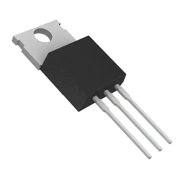
引脚分配:TO-220封装,引脚2与安装底座电气接触。
参数特性:
- 集电极-基极电压:BDW23为45V,BDW23A为60V,BDW23B为80V,BDW23C为100V。
- 集电极-发射极电压:BDW23为60V,BDW23A为80V,BDW23B为80V,BDW23C为100V。
- 发射极-基极电压:5V。
- 连续集电极电流:6A。
- 连续基极电流:0.2A。
- 连续器件耗散功率:在25°C外壳温度下为50W,在25°C自由空气温度下为2W。
功能详解:文档还提供了电气特性、热特性和电阻负载开关特性的详细参数。
应用信息:文档指出这些系列是过时的,不推荐用于新设计。
封装信息:TO-220封装。