CO
M
G E & PL I
AN
N
FR
T*
EE
**
AUTOMOTIVE
HS
LO
HA
Ro
Features
Applications
n High power density
n Power supplies
n High reliability and stability
n Stepper motor drives
n RoHS compliant* and halogen free**
n Input amplifiers
n Metal foil
G R A DE
n Current sensing
PL
IA
NT
n AEC-Q200 Compliant
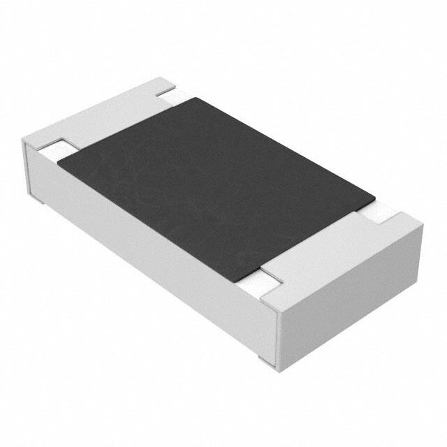
CFN-A Series Metal Foil, Current Sensing Chip Resistor
*R
oH
S
CO
M
Additional Information
Electrical Characteristics
0.5 W
0.75 W
1W
5 mΩ,
10 mΩ,
20 mΩ
5 mΩ,
10 mΩ,
20 mΩ,
30 mΩ
5 mΩ,
10 mΩ,
20 mΩ,
40 mΩ
EE
CFN1206A
10 mΩ,
20 mΩ
-55 ℃ ~ +125 ℃
-55 ℃ ~ +155 ℃
Temperature Coefficient
of Resistance
±100 ppm/°C
±50 ppm/°C & ±100 ppm/°C
PRODUCT
Tolerance
TECHNICAL INVENTORY
LIBRARY
SAMPLES
CONTACT
Derating Curve
Ro VER LEA
HS SI D F
CO ON RE
M SA E
PL R
IA E
NT
*
Operating Temperature
Range
Click these links for more information:
Power Ratio (%)
0.2 W
Resistance Value
CFN0805A
LE
Power Rating @ 70 °C
CFN0603A
FR
CFN0402A
AD
Characteristic
±1 %, ±5 %
100
CFN0603A
CFN0805A
CFN1206A
CFN0402A
-55
70
125
155
Ambient Temperature (°C)
Environmental Characteristics
Storage Conditions
Temperature��������������������������������������������������������������������������������������������������������������������������������������������������������������������+5 °C ~ +35 °C
Humidity����������������������������������������������������������������������������������������������������������������������������������������������������������������������������� 40 % ~ 75 %
Shelf Life�������������������������������������������������������������������������������������������������������������������������������������������������� 2 years from manufacturing date
Solder Recommendations������������������������������������������������������������������������������������������������������������������������������������������������������ Reflow profile
(Solder: Sn96.5 / Ag3 / Cu0.5)
Moisture Sensitivity Level���������������������������������������������������������������������������������������������������������������������������������������������������������������������������1
Product Dimensions
L
W
D
t
CFN0402A
1.10 ± 0.10
(.043 ± .004)
0.55 ± 0.10
(.021 ± .004)
0.25 ± 0.10
(.009 ± .004)
0.45 ± 0.10
(.017 ± .004)
CFN0603A
1.60 ± 0.20
(.063 ± .008)
0.80 ± 0.20
(.031 ± .008)
0.40 ± 0.20
(.016 ± .008)
0.60 ± 0.20
(.024 ± .008)
CFN0805A
2.00 ± 0.20
(.079 ± .008)
1.25 ± 0.20
(.049 ± .008)
0.40 ± 0.20
(.016 ± .008)
0.70 ± 0.20
(.028 ± .008)
CFN1206A
3.20 ± 0.20
(.126 ± .008)
1.60 ± 0.20
(.063 ±. 008)
0.50 ± 0.20
(.020 ± .008)
0.70 ± 0.20
(.028 ± .008)
L
W
C
C
T
DIMENSIONS:
MM
(INCHES)
WARNING Cancer and Reproductive Harm
www.P65Warnings.ca.gov
* RoHS Directive 2015/863, Mar 31, 2015 and Annex.
** Bourns considers a product to be “halogen free” if (a) the Bromine (Br) content is 900 ppm or less; (b) the Chlorine (Cl) content is 900 ppm or less; and (c) the total Bromine (Br)
and Chlorine (Cl) content is 1500 ppm or less.
Specifications are subject to change without notice.
Users should verify actual device performance in their specific applications.
The products described herein and this document are subject to specific legal disclaimers as set forth on the last page of this document, and at www.bourns.com/docs/legal/disclaimer.pdf.
�
CFN-A Series Metal Foil, Current Sensing Chip Resistor
Construction
Recommended Solder Pad Dimensions
L
SOLDER
COATING
TOP PROTECTIVE
COATING
METAL FOIL
B
A
NICKEL
UNDERLAY
SOLDER
COATING
BOTTOM
PROTECTIVE COATING
ALUMINA
SUBSTRATE
Cu Trace
Marking
NICKEL
UNDERLAY
Sensing Trace
METAL FOIL
Model
CFN0805A
CFN0402A
CFN1206A
CFN0603A
005 = 5 mΩ
No Marking
010 = 10 mΩ
020 = 20 mΩ
BOTTOM
ALUMINA
6.5 = 6.5 mΩ
PROTECTIVE COATING
SUBSTRATE
A
L
CFN0402A
10 ≤ R ≤ 20
0.70
(.027)
1.20
(.047)
CFN0603A
10 ≤ R ≤ 20
1.00
(.039)
2.80
(.110)
CFN0805A
10 ≤ R ≤ 30
1.40
(.055)
3.20
(.126)
1.80
(.071)
4.70
(.185)
CFN1206A
20 ≤ R ≤ 30
R = 40
DIMENSIONS:
B
0.45
(.018)
0.60
(.024)
1.20
(.047)
1.60
(.063)
2.20
(.087)
MM
(INCHES)
Specifications are subject to change without notice.
Users should verify actual device performance in their specific applications.
The products described herein and this document are subject to specific legal disclaimers as set forth on the last page of this document, and at www.bourns.com/docs/legal/disclaimer.pdf.
�
CFN-A Series Metal Foil, Current Sensing Chip Resistor
Solder Reflow Recommendations
CRITICAL ZONE
T L TO TP
RAMP-UP
TL
Temperature
tL
TS MAX.
RAMP-DOWN
TS MIN.
Solder Profile
tp
TP
ts
PREHEAT
25 °C
8 MINUTES MAX.
t 25 *C TO PEAK
Time
Average ramp-up rate
(Tsmax to Tp)
Lead Free Assembly
3 °C / second max.
Preheat:
- Temperature Min. (Tsmin)
- Temperature Max. (Tsmax)
- Time (Tsmin to Tsmax) (ts)
150 °C
200 °C
60~150 seconds
Time maintained above:
- Temperature (TL)
- Time (TL)
217 °C
60~120 seconds
Peak Temperature (Tp)
260 °C
Time within +0/-5 °C of actual
Peak Temperature (Tp)2
10 seconds
Ramp-down rate
6 °C / second max.
Time 25 °C to Peak
Temperature
8 minutes max.
How to Order
CFN 0805 A F X - R005 E LF
Model
CFN = Metal Foil Current Sense Resistor
Size
0402 = 0402 Size
0603 = 0603 Size
0805 = 0805 Size
1206 = 1206 Size
Feature
A = AEC-Q200 Compliant
Resistance Tolerance
F = ±1 %
J = ±5 %
TCR
X = ±100 PPM/°C
Z = ±50 PPM/°C
Resistance Code – (See Popular Resistance Table)
“R” (decimal point) followed by three significant digits (example: R005 = 0.005 ohms)
Packaging
E = Tape and Reel
4,000 pcs. / 7-inch reel, paper tape (CFN0805A, CFN1206A)
5,000 pcs. / 7-inch reel, paper tape (CFN0603A)
10,000 pcs. / 7-inch reel, paper tape (CFN0402A)
Termination
LF = Tin-plated (RoHS Compliant)
Specifications are subject to change without notice.
Users should verify actual device performance in their specific applications.
The products described herein and this document are subject to specific legal disclaimers as set forth on the last page of this document, and at www.bourns.com/docs/legal/disclaimer.pdf.
�
CFN-A Series Metal Foil, Current Sensing Chip Resistor
Packaging Dimensions (Conforms to EIA RS-481A)
Top Tape
E
P0
D0 DIA.
Bottom Tape
F
B
Resistor
W
Paper Tape
T
A
A
B
CFN0402A
0.75
(.030)
1.30
(.051)
CFN0603A
1.10
(.043)
1.90
(.075)
CFN0805A
1.60
(.063)
2.40
(.094)
CFN1206A
2.00
(.079)
3.60
(.142)
P1
W
F
P2
E
P1
DIRECTION OF UNREELING
P2
P0
D0
2.00
(.079)
8.00
(.315)
3.50
(.138)
1.75
(.069)
4.00
(.157)
T
0.65
(.026)
2.00
(.079)
4.00
(.157)
1.50
(.059)
0.85
(.033)
1.05
(.041)
1.05
(.041)
9.0 ± 1.0
(.354 ± .039)
13.0 ± 1.0
(.512 ± .039)
DIA.
DIA.
178 ± 2.0
(7.008 ± .079)
DIA.
60.0 ± 1.0
(2.362 ± .039)
DIMENSIONS:
MM
(INCHES)
11.5 ± 1.0
(.453 ± .039)
Asia-Pacific: Tel: +886-2 2562-4117 • Email: asiacus@bourns.com
EMEA: Tel: +36 88 885 877 • Email: eurocus@bourns.com
The Americas: Tel: +1-951 781-5500 • Email: americus@bourns.com
www.bourns.com
Specifications are subject to change without notice.
Users should verify actual device performance in their specific applications.
The products described herein and this document are subject to specific legal disclaimers as set forth on the last page of this document, and at www.bourns.com/docs/legal/disclaimer.pdf.
�CFN-A Series Metal Foil, Current Sensing Chip Resistor
Reliability Tests
Test Items
Reference Standard
Condition of Test
Test Limits
Temperature Coefficient of
Resistance
IEC 60115-1 4.8
+25 ~ 125 °C
Reference item 4
Short Time Overload
IEC 60115-1 4.13
5X rated power for 5 s
< ±1 %
High Temperature
Exposure (Storage)
AEC-Q200-REV D-Test 3
MIL-STD-202 Method 108
1000 hrs @ T = 125 °C. Unpowered.
Measurement at 24 ±2 hours after test conclusion.
< ±1 %
Temperature Cycling
AEC-Q200-REV D-Test 4
JESD22 Method JA-104
1000 cycles (-55 °C to +125 °C). Measurement
at 24 ±4 hours after test conclusion. 30 min. max.
dwell time at each temperature extreme. 1 min.
max. transition time.
< ±1 %
Moisture Resistance
AEC-Q200-REV D-Test 6
MIL-STD-202 Method 106
T = 24 hours/cycle, 10 cycles. Notes: Steps 7a &
7b not required. Unpowered.
< ±1 %
Biased Humidity
AEC-Q200-REV D-Test 7
MIL-STD-202 Method 103
1000 hours 85 °C / 85 % RH. Note: Specified
conditions: 10 % of operating power (not
< ±1 %
exceeding max. working voltage). Measurement at
24 ±2 hours after test conclusion.
Operational Life
AEC-Q200-REV D-Test 8
MIL-STD-202 Method 108
1000 hours TA = 125 °C at 35 % rated power.
Measurement at 24 ±4 hours after test conclusion.
External Visual
AEC-Q200-REV D-Test 9
MIL-STD-883 Method 2009
Electrical test not required. Inspect device
construction, marking and workmanship.
Physical Dimensions
AEC-Q200-REV D-Test 10
JESD22 Method JB-100
Verify physical dimensions to the applicable device
detail specification. Note: User(s) and Suppliers
spec. Electrical test not required.
Resistance to Solvents
AEC-Q200-REV D-Test 12
MIL-STD-202 Method 215
a: Isopropyl Alcohol : Mineral Spirits = 1 : 3
b: Terpene Defluxer (Bioact EC-7R)
c: Deionized Water : Propylene Glycol
Monomethyl Ether : monoethanolamine 42 : 1 : 1
Marking and
protective layer
cannot be
detached
Mechanical Shock
AEC-Q200-REV D-Test 13
MIL-STD-202 Method 213
Wave Form: Tolerance for half sine shock pulse.
Peak value is 100 g’s. Normal duration (D) is 6 ms
< ±1.0 %
Vibration
AEC-Q200-REV D-Test 14
MIL-STD-202 Method 204
5 g’s for 20 min., 12 cycles each of 3 orientations.
Note: Test from 10-2000 Hz.
< ±1.0 %
Resistance to Soldering
Heat
AEC-Q200-REV D-Test 15
MIL-STD-202 Method 210
Condition B: Immerse the specimens in an eutectic
< ±0.5 %
solder at 260 ±5 °C for 10 ±1 s.
Thermal Shock
AEC-Q200-REV D-Test 16
MIL-STD-202 Method 107
-55 °C / +155 °C. Note: Number of cycles required:
300, Maximum transfer time: 20 s, Dwell time: 15
< ±1.0 %
minutes, Air - Air
ESD
AEC-Q200-REV D-Test 17
AEC-Q200-002 or ISO/DIS 10605
Verify the voltage setting at 500 V
< ±1.0 %
Solderability
AEC-Q200-REV D-Test 18
J-STD-202
Method B, aging 4 hours @ 155 °C dry heat.
Lead-free solder bath @ 235 ±3 °C
Dipping time: 3 ±0.5 seconds.
> 95 % area
covered with tin
Flammability
AEC-Q200-REV D-Test 20
UL 94
V-0 or V-1 are acceptable. Electrical test not
required.
V-0 or V-1
Board Flex (Bending)
AEC-Q200-REV D-Test 21
AEC-Q200-005
The duration of the applied forces shall be 60 +5
seconds
3 mm deflection (RLS06 ~ RLS 12)
2 mm deflection (RLS 25)
< ±1.0 %
Terminal Strength (SMD)
AEC-Q200-REV D-Test 22
AEC-Q200-006
Force of 1.8 kg for 60 seconds
Remarks: 0201-NA
< ±1.0 %
05/21
< ±2 %
Specifications are subject to change without notice.
Users should verify actual device performance in their specific applications.
The products described herein and this document are subject to specific legal disclaimers as set forth on the last page of this document, and at www.bourns.com/docs/legal/disclaimer.pdf.
�
Legal Disclaimer Notice
This legal disclaimer applies to purchasers and users of Bourns® products manufactured by or on behalf of Bourns, Inc. and its
affiliates (collectively, “Bourns”).
Unless otherwise expressly indicated in writing, Bourns® products and data sheets relating thereto are subject to change
without notice. Users should check for and obtain the latest relevant information and verify that such information is current and
complete before placing orders for Bourns® products.
The characteristics and parameters of a Bourns® product set forth in its data sheet are based on laboratory conditions, and
statements regarding the suitability of products for certain types of applications are based on Bourns’ knowledge of typical
requirements in generic applications. The characteristics and parameters of a Bourns® product in a user application may vary
from the data sheet characteristics and parameters due to (i) the combination of the Bourns® product with other components
in the user’s application, or (ii) the environment of the user application itself. The characteristics and parameters of a Bourns®
product also can and do vary in different applications and actual performance may vary over time. Users should always verify
the actual performance of the Bourns® product in their specific devices and applications, and make their own independent
judgments regarding the amount of additional test margin to design into their device or application to compensate for
differences between laboratory and real world conditions.
Unless Bourns has explicitly designated an individual Bourns® product as meeting the requirements of a particular industry
standard (e.g., ISO/TS 16949) or a particular qualification (e.g., UL listed or recognized), Bourns is not responsible for any
failure of an individual Bourns® product to meet the requirements of such industry standard or particular qualification. Users of
Bourns® products are responsible for ensuring compliance with safety-related requirements and standards applicable to their
devices or applications.
Bourns® products are not recommended, authorized or intended for use in nuclear, lifesaving, life-critical or life-sustaining applications, nor in any other applications where failure or malfunction may result in personal injury, death, or severe property or
environmental damage. Unless expressly and specifically approved in writing by two authorized Bourns representatives on a
case-by-case basis, use of any Bourns® products in such unauthorized applications might not be safe and thus is at the user’s
sole risk. Life-critical applications include devices identified by the U.S. Food and Drug Administration as Class III devices and
generally equivalent classifications outside of the United States.
Bourns expressly identifies those Bourns® standard products that are suitable for use in automotive applications on such
products’ data sheets in the section entitled “Applications.” Unless expressly and specifically approved in writing by two
authorized Bourns representatives on a case-by-case basis, use of any other Bourns® standard products in an automotive
application might not be safe and thus is not recommended, authorized or intended and is at the user’s sole risk. If Bourns
expressly identifies a sub-category of automotive application in the data sheet for its standard products (such as infotainment
or lighting), such identification means that Bourns has reviewed its standard product and has determined that if such Bourns®
standard product is considered for potential use in automotive applications, it should only be used in such sub-category of
automotive applications. Any reference to Bourns® standard product in the data sheet as compliant with the AEC-Q standard
or “automotive grade” does not by itself mean that Bourns has approved such product for use in an automotive application.
Bourns® standard products are not tested to comply with United States Federal Aviation Administration standards generally
or any other generally equivalent governmental organization standard applicable to products designed or manufactured for
use in aircraft or space applications. Bourns expressly identifies Bourns® standard products that are suitable for use in aircraft
or space applications on such products’ data sheets in the section entitled “Applications.” Unless expressly and specifically
approved in writing by two authorized Bourns representatives on a case-by-case basis, use of any other Bourns® standard
product in an aircraft or space application might not be safe and thus is not recommended, authorized or intended and is at the
user’s sole risk.
The use and level of testing applicable to Bourns® custom products shall be negotiated on a case-by-case basis by Bourns and
the user for which such Bourns® custom products are specially designed. Absent a written agreement between Bourns and the
user regarding the use and level of such testing, the above provisions applicable to Bourns® standard products shall also apply
to such Bourns® custom products.
Users shall not sell, transfer, export or re-export any Bourns® products or technology for use in activities which involve the
design, development, production, use or stockpiling of nuclear, chemical or biological weapons or missiles, nor shall they use
Bourns® products or technology in any facility which engages in activities relating to such devices. The foregoing restrictions
apply to all uses and applications that violate national or international prohibitions, including embargos or international
regulations. Further, Bourns® products and Bourns technology and technical data may not under any circumstance be
exported or re-exported to countries subject to international sanctions or embargoes. Bourns® products may not, without prior
authorization from Bourns and/or the U.S. Government, be resold, transferred, or re-exported to any party not eligible
to receive U.S. commodities, software, and technical data.
To the maximum extent permitted by applicable law, Bourns disclaims (i) any and all liability for special, punitive, consequential,
incidental or indirect damages or lost revenues or lost profits, and (ii) any and all implied warranties, including implied warranties
of fitness for particular purpose, non-infringement and merchantability.
For your convenience, copies of this Legal Disclaimer Notice with German, Spanish, Japanese, Traditional Chinese and Simplified Chinese
bilingual versions are available at:
Web Page: http://www.bourns.com/legal/disclaimers-terms-and-policies
PDF: http://www.bourns.com/docs/Legal/disclaimer.pdf
C1753 05/17/18R
�


 工商网监
湘ICP备2023018690号
工商网监
湘ICP备2023018690号
