IA
NT
Features
■ DC to 2 GHz ■ Flanged model ■ Low VSWR
Applications
■ High power RF transmission
*R
oH
S
CO
M
PL
CHF3020CBF Series Power RF Terminations / Resistors
General Specifications Substrate ......................................... Beo Resistive Film ........................ Thick Film Tab ..................................................... Ag Cover Substrate ...........................AL203 Mounting Flange......... Cu plated with Ni Resistance Termination.................... 50 ohms only Resistor ...See Resistance Value Table Tolerance ....................................... ±5 % Packaging..........................100 pcs./box Absolute Ratings Power ............... See Rated Power Table Frequency..................................2.0 GHz VSWR ............................. 1.30 Maximum Capacitance .................................0.8 pF Resistance Value Table R Value (Ohms) 50 100 200 250 300 Rated Power Version C D How to Order Power (W) 10 25 Code 500 101 201 251 301 Characteristic Curve
100 % of Rated Power 80 60 40 20 0 -55 0 100 150
Heat Sink Temperature (°C)
Product Dimensions
MAX. 1.0 (0.039) 6.5 (0.256) 5.08 (0.200) 3.7 (0.146) 2.57 (0.101) “L” TERMINATION 1 TAB (Available only in 50 ohm) 6.35 (0.250) 7.62 (0.300) 2.54 (0.100)
2.54 (0.100)
3.0 (0.118) DIA. DIMENSIONS = MILLIMETERS (INCHES)
2.54 (0.100)
1.57 (0.062)
0.1 (0.004)
MAX.
3.7 (0.146) 2.57 (0.101) 2.54 (0.100)
1.0 (0.039)
6.5 (0.256)
5.08 (0.200)
CHF 3020 C B F 500 L
Model Size Version C = 10 W D = 25 W Substrate Mount F = Flange Value (see Resistance Value Table) Function L = Termination (50 ohms only) R = Resistor
6.35 (0.250)
“R” RESISTOR 2 TABS
7.62 (0.300)
2.54 (0.100)
3.0 (0.118) DIA.
2.54 (0.100)
1.57 (0.062)
0.1 (0.004)
Mounting High Power Devices
The mounting surface must be flat to less than 0.0254 mm (0.001 ”) and devoid of scratches or burrs. The underside of the flange should be brushed with thermal grease prior to being fastened to the heat sink with mounting screws. The thermal grease will fill any air gaps and help to keep a good thermal contact.
Termination/Resistor Tabs (1 for Termination, 2 for Resistors)
Circuit Board Heat Sink/Ground Plane Flange
Pre-tin the tab prior to installation. Position the tab over the circuit and solder in place. Ensure that the temperature on the surface of the flange does not exceed 110 ˚C when running at 100 % of load. If the temperature increases then derate the power. REV. 09/09
*RoHS Directive 2002/95/EC Jan 27 2003 including Annex. Specifications are subject to change without notice. Customers should verify actual device performance in their specific applications
�
很抱歉,暂时无法提供与“CHF3020CBF500L”相匹配的价格&库存,您可以联系我们找货
免费人工找货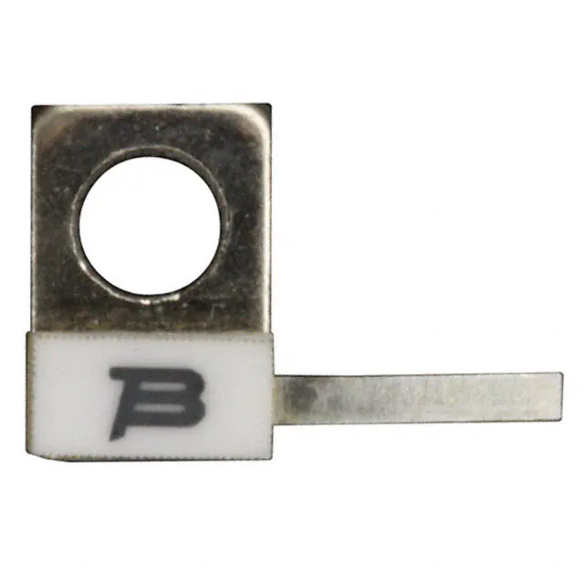


 工商网监
湘ICP备2023018690号
工商网监
湘ICP备2023018690号
