PL
IA
N
T
Features
This series is obsolete and
not recommended for new designs.
M
■ DC to 3 GHz
*R
oH
S
CO
■ Terminals for placement on P.C.B.
■ Low VSWR
■ Aluminum Nitride ceramic
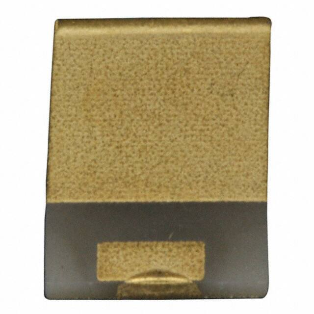
CHF3725CNP Series 40 W SMT Power RF Chip Termination
Characteristic Curve
70
60
Power (Watts)
General Specifications
Substrate .........................................ALN
Resistive Film .........................Thick Film
Resistance ...................................... 50 Ω
Tolerance ........................................±5 %
Packaging
Tape & Reel
......... 3000 pcs./24 mm tape, 15 ” reel
Bulk ................................ 100 pcs./bag
Absolute Ratings
Power .............................................40 W
Frequency.....................................3 GHz
VSWR ............................. 1.25 Maximum
50
40
30
20
10
0
-55
0
100
E
T
E
L
O
S
B
O
150
Heat Sink Temperature (°C)
Product Dimensions
0.99
(0.039)
9.39
(0.37)
9.39
(0.37)
6.35
(0.25)
2.99
(0.118)
1.49
(0.059)
DIMENSIONS = MILLIMETERS
(INCHES)
How To Order
Model
Size
Version
Substrate
Mount
P = Printed Circuit Board
Value
500 = 50 Ohm
Function
L = Termination
Finish
X = Ni Au
Packaging
E = 24 mm Tape & 15 ” Reel (3,000 pcs.)
Blank = Bulk (100 pcs./bag)
1.27
(0.05)
1.52
(0.06)
GROUND PLANE
CHF 3725 C N P 500 L X E
*RoHS Directive 2002/95/EC Jan. 27, 2003 including annex and RoHS Recast 2011/65/EU June 8, 2011.
Specifications are subject to change without notice.
The device characteristics and parameters in this data sheet can and do vary in different applications and actual device performance may vary over time.
Users should verify actual device performance in their specific applications.
�Applications
■ RF amplifiers
■ Attenuators
■ Antenna feeds
CHF3725CNP Series 40 W SMT Power RF Chip Termination
Packaging Dimensions
2.3 ± 0.2
(0.091 = 0.008)
12.0 ± 0.2
(.47 ± .008)
2.0 ± 0.1
(.079 ± .004)
11.5 ± 0.1
(0.45 ± .004)
7.3 ± 0.2
(.287 ± .008)
10.3 ± 0.2
(.405 ± .008)
24
(0.945)
ORIENTATION
OF CHIP
380.0 ± 2.0
(15.0 ± 0.80)
21.0 ± 0.2
(0.827 ± 0.008)
80.0 ± 1.0
(3.15 ± 0.04)
E
T
E
L
O
S
B
O
1.75 ± 0.1
(.050 ± .004)
4.0 ± 0.1
(.157 ± .004)
1.5 +0.1/-0
(.056 +.004/-0)
MAXIMUM THICKNESS:
2.0 +0.2/-0
(0.08 +0.008/-0)
0.3
(.012)
CUMULATIVE TOLERANCE OVER 10 HOLES:
21.0 ± 0.2
(0.827 ± 0.008)
0.2
(.008)
DIMENSIONS:
MM
(INCHES)
REV. 12/15
Specifications are subject to change without notice.
The device characteristics and parameters in this data sheet can and do vary in different applications and actual device performance may vary over time.
Users should verify actual device performance in their specific applications.
24.4 + 2.0/-0.0
(0.96 + 0.08/-0.0)
�
很抱歉,暂时无法提供与“CHF3725CNP500LX”相匹配的价格&库存,您可以联系我们找货
免费人工找货