Features
■
■
■
■
■
Incremental encoder / quadrature output
Exceptionally long operating life
High operating temperature capabilities up to 125°C
Sturdy construction
Bushing mount
■
Available with PC board mounting bracket
(optional)
ECW - Digital Contacting Encoder
Electrical Characteristics
Output .................................................................2-bit gray code, Channel A leads Channel B by 90º electrically turning clockwise (CW)
Closed Circuit Resistance ................................................................................................................................................5 ohms maximum
Open Circuit Resistance .............................................................................................................................................100K ohms minimum
Contact Rating .......................................................................................................................10 milliamp @ 10 VDC or 0.1 watt maximum
Insulation Resistance (500 VDC) .........................................................................................................................1,000 megohms minimum
Dielectric Withstanding Voltage ..........................................................................................................................MIL-STD-202 Method 301
Sea Level ...................................................................................................................................................................1,000 VAC minimum
Electrical Travel...........................................................................................................................................................................Continuous
Contact Bounce (15 RPM) ....................................................................................................................................5 milliseconds maximum
RPM (Operating).....................................................................................................................................................................120 maximum
Environmental Characteristics
Storage Temperature Range ..............................................................................................................................................-40ºC to +140ºC
Operating Temperature Range ............................................................................................................................................+1ºC to +125ºC
Humidity .....................................................................................................................................MIL-STD-202, Method 103B, Condition B
Vibration .................................................................................................................................................................................................15G
Contact Bounce.................................................................................................................................................0.1 millisecond maximum
Shock .....................................................................................................................................................................................................50G
Contact Bounce.................................................................................................................................................0.1 millisecond maximum
Rotational Life .....................................................................................................................................................200,000 shaft revolutions*
Mechanical Characteristics
Mechanical Angle .......................................................................................................................................................................Continuous
Weight ......................................................................................................................................................................Approximately 0.75 oz.
Torque (Detented) ............................................................................................................................................................0.75 to 2.25 oz-in.
Mounting Torque .............................................................................................................................................................7 in-lbs. maximum
Shaft Side Load (Static)......................................................................................................................................................10 lbs. minimum
*Applies to EC Option.
QUADRATURE OUTPUT TABLE
This table is intended to show available outputs as currently defined.
1/4 CYCLE PER DETENT
CW
FULL CYCLE PER DETENT (Normally Open in Detent Shown)
CW
Channel A
Channel A
Closed Circuit
Closed Circuit
Open Circuit
Open Circuit
Closed Circuit
Closed Circuit
Open Circuit
Open Circuit
D D D D D D D D D D D D D D D D D
D
D
Channel B
RECOMMENDED INCREMENTAL
CONTROL DIAGRAM
D
D
Channel B
.0015µf
7
(CUSTOMER LOGIC CIRCUITRY)
9
DIRECTION
5ms DELAY
DEBOUNCE
(MC 14490)
DECODE
LOGIC
UP/DOWN
COUNTER
MAGNITUDE
Specifications are subject to change without notice.
BINARY
OUTPUT
D
�DIGITAL CONTACTING
The Digital Contacting Encoder is commonly referred to by such
names as Digital Panel Control, Bit Switch, Gray Switch and Digital
Switch. All such names are synonymous with a device whose output
is a digital gray code signal, rather than a conventional potentiometric
voltage ratio output.
conversion. The two (2) channel gray coded signal of this incremental
encoder allows the user’s decoder circuit to sense analog direction of
rotation, as well as up-down counter capabilities . . . all without the
time and cost required for A/D conversion. This approach can reduce
memory overhead, wiring and wiring interconnects, and can provide
greater MPU program speed.
The advantage of the Digital Contacting Encoder is that it permits the
direct entry of digitized analog data into a digital circuit without A/D
ECW - Digital Contacting Encoder
22.2 ± 0.25
(.874 ± .010)
BUSHING MOUNTED - HOUSING A
W style bushing shown.
"L"
8.51
(.335)
8.1
(.320)
14.7 ± 0.5
DIA.
(.578 ± .020)
6.35
(.250)
Shaft lengths "L" for B, C, R and Y styles
24 = .750" (19mm)
36 = 1.125" (28.5mm)
28.5 ± 0.25
(1.122 ± .010)
9.0
DIA.
(.354)
M9 X 0.75-6g SPL
27.69 ± 0.25
(1.090 ± .01)
A C B
1.52
(.060)
6.35 ± 0.25
(.250 ± .010)
"L" Dim. = 1.125 or .750
PCB BRACKET MOUNTED - HOUSING B
Dimensions not given are the same as Bushing Mounted.
5.74 ± 0.25
(.226 ± .010)
11.1
(.437)
SOLDER HOLES - HOUSING C
Dimensions not given are the same as Bushing Mounted.
23.37
(.92)
9.02
(.355)
.76
(.030)
4 PLCS.
17.07
(.672)
A
.036 DIA.
3 PLCS.
1.47
(.058)
A C B
SNAP-IN MOUNT - Housing G
13.08
(.515)
22.2 ± 0.25
(.874 ± .010)
8.51
(.335)
6.35
(.250)
9.53
(.375)
11.1
(.437)
29.18 ± 0.25
(1.149 ± .010)
Shaft Style J
5.54 ± .076
(.218 ± .003)
3.94 + .051/ – .025
(.155 + .002/ – .001)
2.54
5.08 (.100)
(.200)
"D"
2X
2.54
(.100)
Shaft Style R
4.75 ± .076
DIA.
(.187 ± .003)
6.32 + 0.03/– 0.07
"D"
DIA.
(.249 + .001/– .003)
"D" DIMENSION EXTENDS FROM SHAFT END TO BUSHING FACE
"D" = (SHAFT LENGTH, FMS) – (BUSHING LENGTH)
PANEL HOLE DIMENSIONS
Bushing Mounted
1.19
(.047)
1.6
(.063)
3.17
DIA.
(.125)
9.1
DIA.
(.360)
1.07
3X
(0.042)
10.90
(.429)
12.24
(.482)
19.76
(.778)
Shaft Style Y
6.00
(.236)
DIA.
1.57
(.062)
4.7
DIA.
(.185)
9.65
FOR SHAFTS
(3.80)
14.7
< 1" LENGTH
FOR SHAFTS ≥ 1" LENGTH
(5.20)
SLOT DEPTH ("Y" SHAFT)
PCB MOUNTING DIMENSIONS
(Housing Styles B and E)
CL
9.5
(.375)
21.11
(.831)
.97
8X
R
(.038)
.635
(.025)
3PLCS.
DIA.
Shaft Style C
1.19
(.047)
5.08
(.200)
22.68
11.33 (.893)
(.446)
14.7 ± 0.5
DIA.
(.578 ± .020)
1.52
(.060)
6.32 + 0.03/– 0.07
DIA.
(.249 + .001/– .003)
1.6
(.063)
2.54
(.100)
28.5 ± 0.25
(1.122 ± .010)
8.99
DIA.
(.354)
Shaft Style B
B
PCB MOUNTING DIMENSIONS
"L"
7.23 ± 0.25
(.285 ± .010)
16.0
(0.630)
C
15.2
(.600)
23.6
(.930)
11.4
(.450)
2.54
TYP.
(.100)
1.2
DIA. 7 PLCS.
(.047)
FOR TOLERANCES NOT SHOWN
.XX = ±.010
.XXX = ± .005
SHAFT DIMENSIONS ± 1/32"
A C B
DIMENSIONS ARE:
METRIC
(INCHES)
CHANNEL A
CHANNEL B
COMMON
Specifications are subject to change without notice.
�ECW - Digital Contacting Encoder - How To Order
PART NUMBERING SYSTEM
E C W 1 J
-
B 2 4
- B C 0 0 2 4
PERFORMANCE CODE
Code Detents Cycles/Rev.
E0006
6
E0009
9
E0012
0
12
E0024
24
B0012
12
12
C0006
6
24
C0024
24
36
D0009
9
Code Rotational Life
C
200,000 Revolutions
BUSHING CONFIGURATION
Code Description
W
9mm x 1/4" Length. Threaded M9x0.75
L
9mm x 3/8" Length. Threaded M9x0.75
(Use B shaft only.)
T
9mm x 1/4". No Thread.
SWITCHING CONFIGURATION (In Detent Position)
Applies to performance codes B0012 and C0024
only, use code "0" for all other performance codes.
Code Description
0
Not Applicable
1
Normally Open
2
Normally Closed
HOUSING TERMINAL CONFIGURATION
(X indicates "Equipped With"
Code
Features
A B C D E F G*
Terminal Cover
X X
X
X
Terminals
X X
X
X
Solder Holes
X X
X
PCB Bracket
X
X X X
Hardware Included
X
X
X X
Snap-In Mount
X
ANTI-ROTATION LUG POSITION
Code Description
J
9:00 Position
D
None
*Bushing code T only.
SHAFT LENGTH (FMS)
SHAFT STYLE (See Outline Drawing for Details)
Code Description
B
Plain with Inserted Slot (1/4" Dia.)
C
Single Flatted (1/4" Dia.)
R
Plain with Inserted Slot (6mm Dia.)
Y
Split Shaft Version (.185" Dia.)
J
Flatted Shaft (3/16" Dia.)
The sample part number demonstrates the identification
code for Bourns contacting encoders.
The part number shown is a commonly used model,
typically available from stock.
Specifications are subject to change without notice.
Code
16
20
24
28
32
36
19
22
24
Available
Description
Shaft Styles
1/2" Length
B
5/8" (15.9mm) Length
J
3/4" (19mm) Length
B, C, J, Y
7/8" (22.2mm) Length
B, C, J, Y
1" (25.4mm) Length
B, C, J, Y
1-1/8" (28.6mm) Length B, C, J, Y
Metric
19mm Length
R
22mm Length
R
24mm Length
R
�
很抱歉,暂时无法提供与“ECW1J-B24-BC0024”相匹配的价格&库存,您可以联系我们找货
免费人工找货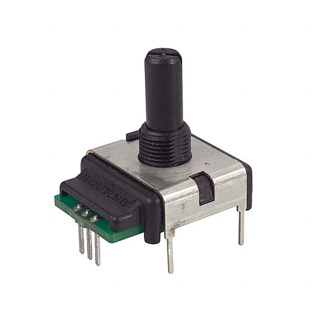


 工商网监
湘ICP备2023018690号
工商网监
湘ICP备2023018690号
