PL
IA
NT
Features
■ Standard 4532 mm (1812 mils) footprint
*R
oH
S
CO
M
■ 100 % electrically compatible with all
■
■
■
■
previous generations of 1812 SMT devices
Compatible with Pb and Pb-free solder
reflow profiles
RoHS compliant* and halogen free**
Surface mount packaging for automated
assembly
Agency recognition:
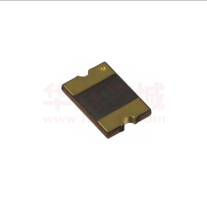
MF-MSMF L Series - PTC Resettable Fuses
Electrical Characteristics
Ihold
Model
V max.
Volts
I max.
Amps
Itrip
Amperes
at 23 °C
Max. Time
To Trip
Resistance
Ohms
at 23 °C
Hold
Trip
RMin.
Amperes
at 23 °C
Seconds
at 23 °C
Tripped
Power
Dissipation
Watts
at 23 °C
R1Max.
Typ.
MF-MSMF110L
6.0
100
1.10
2.20
0.04
0.21
8.0
0.30
0.8
MF-MSMF150L
6.0
100
1.50
3.00
0.03
0.120
8.0
0.5
0.8
MF-MSMF160L
8.0
100
1.60
2.80
0.035
0.099
8.0
2.0
0.8
MF-MSMF200L
8.0
40
2.00
4.00
0.020
0.080
8.0
3.0
0.8
MF-MSMF260L
6.0
100
2.60
5.20
0.015
0.080
8.0
5.0
0.8
Environmental Characteristics
Operating Temperature......................................... -40 °C to +85 °C
Maximum Device Surface Temperature
in Tripped State .................................................... 125 °C
Passive Aging ....................................................... +85 °C, 1000 hours............................................... ±5 % typical resistance change
Humidity Aging ..................................................... +85 °C, 85 % R.H. 1000 hours ............................. ±5 % typical resistance change
Thermal Shock ..................................................... +85 °C to -40 °C, 20 times ................................... ±10 % typical resistance change
Solvent Resistance ............................................... MIL-STD-202, Method 215 ................................... No change
Vibration ............................................................... MIL-STD-883C, Method 2007.1, .......................... No change
Condition A
Test Procedures And Requirements For Model MF-MSMF L Series
Test
Test Conditions
Accept/Reject Criteria
Visual/Mech. ......................................................... Verify dimensions and materials ........................... Per MF physical description
Resistance ............................................................ In still air @ 23 °C .................................................. Rmin ≤ R ≤ R1max
Time to Trip........................................................... At specified current, Vmax, 23 °C ........................ T ≤ max. time to trip (seconds)
Hold Current ......................................................... 30 min. at Ihold ..................................................... No trip
Trip Cycle Life ....................................................... Vmax, Imax, 100 cycles ........................................ No arcing or burning
Trip Endurance ..................................................... Vmax, 48 hours ..................................................... No arcing or burning
Solderability .......................................................... ANSI/J-STD-002 ................................................... 95 % min. coverage
UL File Number .................................................... E174545
http://www.ul.com/ Follow link to Certifications, then UL File No., enter E174545
Asia-Pacific: Tel: +886-2 2562-4117 • Fax: +886-2 2562-4116
Europe: Tel: +41-41 768 5555 • Fax: +41-41 768 5510
The Americas: Tel: +1-951 781-5500 • Fax: +1-951 781-5700
www.bourns.com
*RoHS Directive 2002/95/EC Jan 27 2003 including Annex.
**Bourns is using the definition that appears to be the prevalent definition used as the industry standard at this time. The Bourns definition of “halogen-free” is:
Bromine (Br) content: ≤ 900 ppm; Chlorine (Cl) content: ≤ 900 ppm; Total Br + Cl content: ≤1500 ppm.
Specifications are subject to change without notice.
Customers should verify actual device performance in their specific applications.
�Applications
■ Overcurrent and overtemperature
■ Point-of-sale (POS) equipment
protection of automotive electronics
■ Hard disk drives
■ PC motherboards
■ PC peripherals
■ PCMCIA cards
■ USB port protection - USB 2.0, 3.0 & OTG
■ HDMI 1.4 Source protection
MF-MSMF L Series - PTC Resettable Fuses
Product Dimensions
A
Model
B
C
D
Min.
Max.
Min.
Max.
Min.
Max.
Min.
MF-MSMF110L
4.37
(0.172)
4.73
(0.186)
3.07
(0.121)
3.41
(0.134)
0.45
(0.018)
0.85
(0.033)
0.30
(0.012)
MF-MSMF150L
4.37
(0.172)
4.73
(0.186)
3.07
(0.121)
3.41
(0.134)
0.55
(0.015)
0.85
(0.033)
0.30
(0.012)
MF-MSMF160L
4.37
(0.172)
4.73
(0.186)
3.07
(0.121)
3.41
(0.134)
0.55
(0.015)
0.85
(0.033)
0.30
(0.012)
MF-MSMF200L
4.37
(0.172)
4.73
(0.186)
3.07
(0.121)
3.41
(0.134)
0.45
(0.018)
0.85
(0.033)
0.30
(0.012)
MF-MSMF260L
4.37
(0.172)
4.73
(0.186)
3.07
(0.121)
3.41
(0.134)
0.48
(0.019)
0.85
(0.033)
0.30
(0.012)
Packaging: 2000 pcs. per reel.
Top View
DIMENSIONS:
Bottom View
Side View
A
Recommended Pad Layout
C
110
MM
(INCHES)
1.5 ± 0.05
(.059 ± .002)
1.5 ± 0.05
(.059 ± .002)
3.2 ± 0.1
(0.126 ± .004)
B
Termination pad solderability:
Standard Au finish:
Meets ANSI/J-STD-002 Category 2.
Recommended Storage:
40 °C max./70 % RH max.
2.7 ± 0.1
(.106 ± .004)
D
Terminal material:
Electroless Ni under immersion Au
Typical Time to Trip at 23 ˚C
100
MF-MSMF200L
The Time to Trip curves represent typical
performance of a device in a simulated
application environment. Actual performance
in specific customer applications may differ
from these values due to the influence of
other variables.
Time to Trip (Seconds)
10
1
MF-MSMF260L
0.1
MF-MSMF160L
MF-MSMF150L
0.01
MF-MSMF110L
0.001
0.1
1
10
100
Fault Current (Amps)
Specifications are subject to change without notice.
Customers should verify actual device performance in their specific applications.
�3312
- 2 mm
SMD -Trimming
Potentiometer
MF-MSMF
L Series
PTC Resettable
Fuses
Thermal Derating Chart - Ihold (Amps)
Ambient Operating Temperature
Model
-40 ˚C
-20 ˚C
0 ˚C
23 ˚C
40 ˚C
50 ˚C
60 ˚C
70 ˚C
85 ˚C
MF-MSMF110L
1.59
1.43
1.26
1.10
0.95
0.87
0.80
0.71
0.60
MF-MSMF150L
2.17
1.95
1.72
1.50
1.30
1.18
1.09
0.97
0.82
MF-MSMF160L
2.30
2.20
1.90
1.60
1.45
1.30
1.15
1.03
0.91
MF-MSMF200L
3.08
2.71
2.35
2.00
1.80
1.60
1.50
1.40
1.25
MF-MSMF260L
4.00
3.52
3.06
2.60
2.34
2.08
1.95
1.39
1.04
Solder Reflow Recommendations
Preheating
300
Soldering
Cooling
Notes:
Temperature (°C)
250
200
•
MF-MSMF models cannot be wave soldered. Please contact Bourns for
hand soldering recommendations.
•
If reflow temperatures exceed the recommended profile, devices may
not meet the performance requirements.
150
100
•
Compatible with Pb and Pb-free solder reflow profiles.
•
Excess solder may cause a short circuit, especially during hand
soldering. Please refer to the Multifuse® Polymer PTC Soldering
Recommendation guidelines.
50
0
160–220
10–20
120
Time (seconds)
MF - MSMF 110 L - 2
Multifuse® Product
Designator
Series
MSMF = 4532 mm (1812 mils)
Surface Mount Component
Hold Current, Ihold
110-260 (1.10 Amps - 2.60 Amps)
Model Suffix
Packaging
Packaged per EIA 481-1
-2 = Tape and Reel
Typical Part Marking
Represents total content. Layout may vary.
110
How to Order
MF-MSMF L SERIES, REV. A, 01/11
“freeXpansion Design” is a trademark of Bourns, Inc.
Specifications are subject to change without notice.
Customers should verify actual device performance in their specific applications.
PART IDENTIFICATION EXAMPLES:
MF-MSMF110L = 110
MF-MSMF150L = 150
MF-MSMF160L = 160
MF-MSMF200L = 200
MF-MSMF260L = 260
�MF-MSMF L Series Tape and Reel Specifications
MF-MSMF L Series
per EIA 481-1
12.0 ± 0.30
(0.472 ± 0.012)
4.0 ± 0.10
(0.157 ± 0.004)
8.0 ± 0.10
(0.315 ± 0.004)
2.0 ± 0.05
(0.079 ± 0.002)
3.66 ± 0.15
(0.144 ± 0.006)
4.98 ± 0.10
(0.196 ± 0.004)
5.9
(0.232)
1.5 + 0.10/-0.0
(0.059 + 0.004/-0)
5.5 ± 0.05
(0.217 ± 0.002)
1.75 ± 0.10
(0.069 ± 0.004)
10.25
(0.404)
0.6
(0.024)
0.1
(0.004)
0.95 ± 0.10
(0.037 ± 0.004)
390
(15.35)
160
(6.30)
Tape Dimensions
W
P0
P1
P2
A0
B0
B1 max.
D0
F
E1
E2 min.
T max.
T1 max.
K0
Leader min.
Trailer min.
Reel Dimensions
185
(7.28)
50
(1.97)
12.4 + 2.0/-0.0
(0.488 + 0.079/-0.0)
18.4
(0.724)
A max.
N min.
W1
W2 max.
DIMENSIONS:
P0
T
D0
P2
E1
MM
(INCHES)
W2(MEASURED
AT HUB)
COVER
TAPE
F
E2 W
B1
A
N(HUB DIA.)
B0
K0
T1
P1
A0
Specifications are subject to change without notice.
Customers should verify actual device performance in their specific applications.
W1(MEASURED
AT HUB)
�
很抱歉,暂时无法提供与“MF-MSMF200L-2”相匹配的价格&库存,您可以联系我们找货
免费人工找货- 国内价格
- 5+0.34655
- 20+0.31597
- 100+0.28539
- 500+0.25482
- 1000+0.24055
- 2000+0.23035
- 国内价格
- 10+0.25542
- 100+0.19970
- 300+0.17194
- 2000+0.15110
- 4000+0.13436