Features
n RoHS compliant*
n Space saving design
Additional Information
Click these links for more information:
n Wide range of resistance values
n Metric shaft and bushing option
n Mounting brackets available
PRODUCT TECHNICAL INVENTORY SAMPLES
LIBRARY
CONTACT
n Linear or audio taper versions
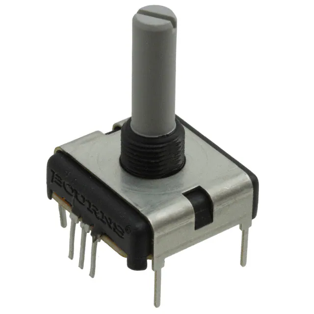
PC - “Slimline” 22 mm Square Single Turn Panel Control
Electrical Characteristics1
Standard Resistance Range
Linear Tapers����������������������������������������������������������������������������������������������������������������������������������������������������������������� 500 ohms to 1 megohm
Audio Tapers�����������������������������������������������������������������������������������������������������������������������������������������������������������������1 K ohms to 500 K ohms
Total Resistance Tolerance������������������������������������������������������������������������������������������������������������������������������������������������������������������������������ ±20 %
Independent Linearity���������������������������������������������������������������������������������������������������������������������������������������������������������������������������������������� ±5 %
Absolute Minimum Resistance������������������������������������������������������������������������������������������������������������������������������������������������������5 ohms maximum
Effective Electrical Angle�������������������������������������������������������������������������������������������������������������������������������������������������������������������������� 270 ° ± 5 °
Contact Resistance Variation�������������������������������������������������������������������������������������������������������������������������������������������������7 % of total resistance
Dielectric Withstanding Voltage (MIL-STD-202, Method 301)
Sea Level�����������������������������������������������������������������������������������������������������������������������������������������������������������������������������1,000 VAC minimum
70,000 Feet����������������������������������������������������������������������������������������������������������������������������������������������������������������������������500 VAC minimum
Insulation Resistance (500 V)�������������������������������������������������������������������������������������������������������������������������������������������������1,000 ohms minimum
Power Rating @ 70 ºC (Voltage Limited by Power Dissipation or 350 VAC, Whichever is Less)
Linear����������������������������������������������������������������������������������������������������������������������������������������������������������������������������������������������������� .75 watt
Audio����������������������������������������������������������������������������������������������������������������������������������������������������������������������������������������������������� .25 watt
Theoretical Resolution�������������������������������������������������������������������������������������������������������������������������������������������������������������������Essentially infinite
Environmental Characteristics
Operating Temperature Range��������������������������������������������������������������������������������������������������������������������������������������������������������������+1 °C to +125 °C
Storage Temperature Range����������������������������������������������������������������������������������������������������������������������������������������������������������������-40 °C to +125 °C
Temperature Coefficient Over Storage Temperature Range��������������������������������������������������������������������������������������������������������������������� ±1000 ppm/°C
Vibration���������������������������������������������������������������������������������������������������������������������������������������������������������������������������������������������������������������������20 G
Total Resistance Shift������������������������������������������������������������������������������������������������������������������������������������������������������������������������ ±1 % maximum
Voltage Ratio Shift��������������������������������������������������������������������������������������������������������������������������������������������������������������������������� ±20 % maximum
Shock�������������������������������������������������������������������������������������������������������������������������������������������������������������������������������������������������������������������������50 G
Total Resistance Shift������������������������������������������������������������������������������������������������������������������������������������������������������������������������ ±1 % maximum
Voltage Ratio Shift��������������������������������������������������������������������������������������������������������������������������������������������������������������������������� ±20 % maximum
Load Life������������������������������������������������������������������������������������������������������������������������������������������������� 1,000 Hours @ Rated Power, 20 % RH, 70 ºC
Total Resistance Shift���������������������������������������������������������������������������������������������������������������������������������������������������������������������� ±10 % maximum
Rotational Life (No Load)���������������������������������������������������������������������������������������������������������������������������������������������������������������������������� 50,000 cycles
Total Resistance Shift (Linear taper)���������������������������������������������������������������������������������������������������������� ±10 ohms or 12 %, whichever is greater
Total Resistance Shift (Audio taper)������������������������������������������������������������������������������������������������������������������������������������������������ ±20 % maximum
Contact Resistance Variation������������������������������������������������������������������������������������������������������������������������������������������������������������������� ±5 % maximum
Moisture Resistance����������������������������������������������������������������������������������������������������������������������������������������� MIL-STD-202, Method 103, Condition B
Total Resistance Shift���������������������������������������������������������������������������������������������������������������������������������������������������������������������� ±20 % maximum
IP Rating�������������������������������������������������������������������������������������������������������������������������������������������������������������������������������������������������������������������� IP 40
Mechanical Characteristics
Stop Strength (1/4 ˝ and 6 mm Shaft Diameters)��������������������������������������������������������������������������������������������������������������������������� 79.09 N-cm (7 lb.-in.)
Mechanical Angle����������������������������������������������������������������������������������������������������������������������������������������������������������������������������������������������300 ° ± 5 °
Torque
Starting (Detented)����������������������������������������������������������������������������������������������������������������������������������������������������0.5-1.5 N-cm (0.75-2.25 oz.-in.)
Starting (Undetented)����������������������������������������������������������������������������������������������������������������������������������������������1.5 N-cm (2.25 oz.-in.) maximum
Running (Undetented)����������������������������������������������������������������������������������������������������������������������������������� 0.18 to 1.06 N-cm (0.25 to 1.5 oz.-in.)
Mounting�������������������������������������������������������������������������������������������������������������������������������������������������������������������79.09 N-cm (7 lb.-in.) maximum
Weight (Single Section)��������������������������������������������������������������������������������������������������������������������������������������������������������� 21 gm (0.75 oz.) maximum
Terminals�����������������������������������������������������������������������������������������������������������������������������������������������������������������������������������������������������������������PC pin
Soldering Condition
Manual Soldering����������������������������������������������������������������������������������������������������������96.5Sn/3.0Ag/0.5Cu solid wire or no-clean rosin cored wire
370 °C (700 °F) max. for 3 seconds
Wave Soldering�����������������������������������������������������������������������������������������������������������������������������������96.5Sn/3.0Ag/0.5Cu solder with no-clean flux
260 °C (500 °F) max. for 5 seconds
Wash processes����������������������������������������������������������������������������������������������������������������������������������������������������������������������������Not recommended
Marking���������������������������������������������������������������������������������������������������������Manufacturer’s trademark, resistance value, part number, and date code
Ganging����������������������������������������������������������������������������������������������������������������������������������������������������������������������������������������������������1 cup maximum
Hardware���������������������������������������������������������������������One lockwasher (H-37-2) and one mounting nut (H-38-11) is shipped with each potentiometer
Detents����������������������������������������������������������������������������������������������������������������������������������������������������������������������������������������Center, 10, 20, 30, none
For additional features or specifications not shown, consult factory.
FOR ORDERING INFORMATION SEE PAGE 4.
Electrical specifications tested at 200 RPM, at room ambient: +25 °C nominal.
*RoHS Directive 2015/863, Mar 31, 2015 and Annex.
Specifications are subject to change without notice. Users should verify actual device performance in their specific
applications. The products described herein and this document are subject to specific legal disclaimers as set forth on the
last page of this document, and at www.bourns.com/docs/legal/disclaimer.pdf.
1
WARNING
Cancer and Reproductive Harm
www.P65Warnings.ca.gov
�
PC – “Slimline” 22 mm Square Single Turn Panel Control
Product Dimensions
Axial PC Pins
14.7 ± 0.5
DIA.
(.578 ± .020)
22.2 ± 0.25
(.874 ± .010)
"F"
7.42
(.292)
"L"
11.1
(.437)
PANEL HOLE DIMENSIONS
9.53
(.375)
1 2 3
9.0
DIA.
(.354)
M9 X 0.75-6g SPL
6.25
(.246)
.320
(8.13)
1.52
(.060)
"F" =
11.1
(.437)
6.35
9.53
OR
(.250)
(.375)
"E" =
3.18
DIA.
(.125)
0.79
3 PLCS.
(.031)
9.14
DIA.
(.360)
"E" 2 PLCS.
2.54
5.08
OR
(.100)
(.200)
"L" = SEE SHAFT LENGTH TABLE
Radial PC Pins
22.2 ± 0.25
(.874 ± .010)
"L"
14.7 ± 0.5
(.578 ± .020)
DIA.
"F"
.320
(8.13)
11.1
(.437)
1 2 3
8.36
(.329)
.28
(.011)
3 PLCS.
PANEL HOLE DIMENSIONS
9.53
(.375)
3.18
DIA.
(.125)
11.1
(.437)
6.25
(.246)
0.79
(.031) 3 PLCS.
"E" 2 PLCS.
"F" =
9.14
DIA.
(.360)
6.35
9.53
OR
(.250)
(.375)
"E" =
2.54
5.08
OR
(.100)
(.200)
DIMENSIONS:
MM
(INCHES)
"L" = SEE SHAFT LENGTH TABLE
TOLERANCES EXCEPT WHERE NOTED:
2
3
1
.25
(.010)
.13
.XXX = ±
(.005)
.XX = ±
Hardware
Date Code Description
LOCKWASHER H-37-2
YYWWM
NUT H-38-11
13 ± 0.3
(.512 ± .012)
9.58 ± 0.36
(.377 ± .014)
2.3 ± 0.2
(.091 ± .008)
M9 x .75
M = COUNTRY OF MANUFACTURE
(MEXICO)
WW = WEEK NUMBER
YY = LAST TWO DIGITS OF YEAR
MANUFACTURED
12.52 ± 0.36
(.493 ± .014)
DIMENSIONS:
0.56 ± 0.05
(.022 ± .002)
30 ° ± 15 ° TYP.
MM
(INCHES)
Specifications are subject to change without notice.
Users should verify actual device performance in their specific applications.
The products described herein and this document are subject to specific legal disclaimers as set forth on the last page of this document, and at www.bourns.com/docs/legal/disclaimer.pdf.
�SOLDER LUGS
"L"
(Dimensions not given are the same as
Axial PC pins.
"F"
22.2 ± 0.25
(.874 ± .010)
8.36
(.329)
PC – “Slimline” 22 mm Square Single Turn Panel Control
.28
3 PLCS.
(.011)
Product Dimensions
Axial PC PINS
With Rear Mounting Bracket
7.75
(.305)
6.25
(.246)
6.83
(.269)
5.08
(.200)
2 PLCS.
1.02 X 2.29
3 PLCS.
(.040 X .090)
2.03
3 PLCS.
(.080)
23.37
(.92)
"L"
8.31
(.327)
6.35
9.53
"F" =
OR
(.250)
(.375)
11.43
(.450)
2 PLCS.
"E" 2 PLCS.
15.2
18.87 (.600)
(.743)
0.76
(.030)
4 PLCS.
17.07
(.672)
1.19
DIA. 7 PLCS.
(.047)
2.54
5.08
"E" =
OR
(.100)
(.200)
5.87
(.231)
Radial PC PINS
With Side Mounting Bracket
"L"
1.19
DIA. 7 PLCS.
(.047)
5.48
(.216)
23.37
(.92)
7.62
(.300)
2 PLCS.
5.08
(.200)
17.07
(.672)
12.62
(.497)
0.76
4 PLCS.
(.030)
6.83
(.269)
0.79
(.031) 3 PLCS.
"E" 2 PLCS.
"E" 2 PLCS.
11.43
2 PLCS.
(.450)
2.54
5.08
"E" =
OR
(.100)
(.200)
SHAFT STYLES AND ORIENTATION (Full CCW Rotation)
Shaft Style C
Shaft Style J
"D"
Shaft Style R
6.32 + 0.03/ - 0.08
(.249 + .001/ - .003)
DIA.
4.75 ± .051
DIA.
(.187 ± .002)
"D"
Shaft Style B
"D" dimensions extend from shaft end to bushing face
1.19
(.047)
1.6
(.063)
1.6
(.063)
"D" = (shaft length, FMS) – (bushing length)
Shaft Orientations
Shaft Styles C, J
Shaft Style Y
6.32 + 0.03/ - 0.08
(.249 + .001/ - .003)
DIA.
6.00 ± 0.05
DIA.
(.236 ± .002)
3.94 + .051/ - .025
(.155 + .002/ - .001)
5.54 ± .076
(.218 ± .003)
Shaft Styles B, R
60 ° ± 2 °
1.57
(.062)
1.19
(.047)
DIA.
4.7 ± 0.05
(.185 ± .002)
Slot depth (Y shaft) 9.65 (.380)
for shafts
很抱歉,暂时无法提供与“PCW1D-R24-BAB105L”相匹配的价格&库存,您可以联系我们找货
免费人工找货