T
PL
IA
N
M
CO
*R
oH
S
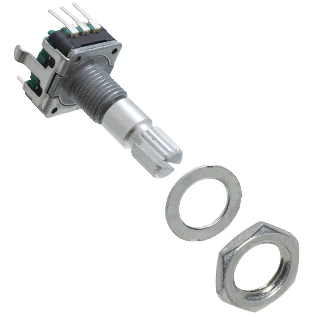
Features
■ Push switch option
■ Compact, rugged design
Model PEC11 is currently available,
but will be replaced by the Model
PEC11R per Product Change
Notification details.
■ High reliability
■ Metal bushing/shaft
PEC11 Series - 12 mm Incremental Encoder
Electrical Characteristics
Output ....................................................................................................................................................................................................2-bit quadrature code
Closed Circuit Resistance ...........................................................................................................................................................................3 ohms maximum
Contact Rating ................................................................................................................................................................................................ 1 mA @ 5 VDC
Insulation Resistance ...................................................................................................................................................................100 megohms @ 250 VDC
Dielectric Withstanding Voltage
Sea Level ............................................................................................................................................................................................... 300 VAC minimum
Electrical Travel .....................................................................................................................................................................................................Continuous
Contact Bounce (15 RPM).........................................................................................................................................................................5.0 ms maximum**
RPM (Operating) ..............................................................................................................................................................................................60 maximum**
Environmental Characteristics
Operating Temperature Range .......................................................................................................................................-30 °C to +70 °C (-22 °F to +158 °F)
Storage Temperature Range ..........................................................................................................................................-40 °C to +85 °C (-40 °F to +185 °F)
Humidity................................................................................................................................................................. MIL-STD-202, Method 103B, Condition B
Vibration .......................................................................................................................................................................................................................... 30 G
Contact Bounce .................................................................................................................................................10~55~10 Hz / 1 min. / Amplitude 1.5 mm
Shock............................................................................................................................................................................................................................. 100 G
Rotational Life.................................................................................................................................................................................... 30,000 cycles minimum
Switch Life ......................................................................................................................................................................................... 20,000 cycles minimum
IP Rating ..........................................................................................................................................................................................................................IP 40
Mechanical Characteristics
Mechanical Angle ......................................................................................................................................................................................... 360 ° continuous
Torque
Running .......................................................................................................................................................................50 to 200 gf.cm (0.68 to 2.7 oz.-in.)
Mounting .......................................................................................................................................................................10.2 kgf.cm (8.83 lb.-in.) maximum
Shaft Side Load (Static)................................................................................................................................................................2.04 kgf (4.5 lbs.) minimum
Weight ............................................................................................................................................................................................ 5 gm (0.17 oz.) maximum
Terminals ................................................................................................................................................................................. Printed circuit board terminals
Soldering Condition
Wave Soldering ...................................................................................... Sn95.5/Ag2.8/Cu0.7 solder with no-clean flux: 260 °C max. for 3-5 seconds
Hand Soldering ................................................................................................................................................................................. Not recommended
Hardware ....................................................................................................................... One flat washer and one mounting nut supplied with each encoder
Switch Characteristics
Switch Type ....................................................................................................................................................................Contact Push ON Momentary SPST
Power Rating (Resistive Load) ..................................................................................................................................................................... 10 mA at 5 V DC
Switch Travel ...................................................................................................................................................................................................... 0.5 ± 0.2 mm
Switch Actuation Force ........................................................................................................................................................610 ± 306 gf (8.47 ± 4.24 oz.-in.)
How To Order
Quadrature Output Table
PEC11 - 4 0 20 F - S 0012
Model
Terminal Configuration
4 = PC Pin Horizontal/Rear Facing
Detent Option
0 = No Detents (12, 18, 24 pulses)
1 = 18 Detents (18 pulses)
2 = 24 Detents (12, 24 pulses)
3 = 12 Detents (12 pulses)
Standard Shaft Length
15 = 15.0 mm
20 = 20.0 mm
25 = 25.0 mm
30 = 30.0 mm
Shaft Style
F = Metal Flatted Shaft
K = Metal Knurled Shaft1
Switch Configuration
S = Push Momentary Switch
N = No Switch
Resolution
0012 = 12 Pulses per 360 ° Rotation
0018 = 18 Pulses per 360 ° Rotation
0024 = 24 Pulses per 360 ° Rotation
1 Metal knurled shaft with no switch is available in 15, 20 and 30 mm shaft lengths.
Metal knurled shaft with push momentary switch is available in 15 and 20 mm shaft lengths.
CW
OFF
A Signal
ON
B Signal
*RoHS Directive 2002/95/EC Jan 27, 2003 including Annex.
**Devices are tested using standard noise reduction filters. For optimum performance, designers should use noise reduction filters in their circuits.
Specifications are subject to change without notice.
Customers should verify actual device performance in their specific applications.
D
CCW
�Applications
Level control, tuning and timer settings in:
■ Audio-visual equipment
■ Consumer electric appliances
■ Radios
■ Musical instrumentation
■ Communications equipment
PEC11 Series - 12 mm Incremental Encoder
Product Dimensions
PEC11-4xxxF-Nxxxx
6.5
(.256)
L1
12.5
(.492)
LB
13.2
(.520)
2 PLCS.
1.8
(.071)
C0.5
13.2
(.520)
7.5
(.295)
l
A
0.9
(.035)
2.5
(.098)
4.5 +0/-0.05
M7x0.75
(.177 +0/-.002)
3.5
6.0
(.138)
DIA.
(.236)
MOUNTING SURFACE
C
2 PLCS.
2.6
(.102)
B
A
14.0
(.551)
2.5
(.098)
C
1.0 +0.1/-0
(.039 +.004/-0)
DIA. 3 PLCS.
2.5
(.098)
B
2.5
(.098)
A CHANNEL A
C COMMON
B CHANNEL B
PEC11-4xxxF-Sxxxx
6.5
(.256)
L1
SWITCH
TRAVEL
0.5
(.020)
LB
13.2
(.520)
12.5
(.492)
5.0
(.197)
2 PLCS.
1.8
(.071)
C0.5
7.0
(.276)
13.2
(.520)
7.5
(.295)
l
0.9
(.035)
2.5
(.098)
4.5 +0/-0.05
(.177 +0/-.002)
3.5
6.0
(.138)
DIA.
(.236)
MOUNTING SURFACE
M7x0.75
A
C
2 PLCS.
B
A
14.0
(.551)
A CHANNEL A
C COMMON
B CHANNEL B
L1
LB
l
15
(.591)
5.0
(.197)
7.0
(.276)
20
(.787)
7.0
(.276)
10.0
(.394)
25
(.984)
7.0
(.276)
12.0
(.472)
30
(1.181)
7.0
(.276)
12.0
(.472)
2.6
(.102)
2.5
(.098)
C
2.5
(.098)
DIMENSIONS:
B
1.0
DIA. 5 PLCS.
(.039)
2.5
(.098)
MM
(INCHES)
Specifications are subject to change without notice.
Customers should verify actual device performance in their specific applications.
�PEC11 Series - 12 mm Incremental Encoder
Product Dimensions
PEC11-4xxxK-Nxxxx
3.5
(.138)
6.5
(.256)
12.5
(.492)
L
LB
P
2.4
7.0 (.094)
(.276)
13.2
(.520)
18 TEETH
2 PLCS.
1.8 +0.2/-0
(.071 +.008/-0)
A
13.2
(.520)
7.5
(.295)
2.6 +0.2/-0
(.102 +.008/-0)
2 PLCS.
7.5
(.295)
1.0
(.039)
A
A
M7x0.75
DIA.
6.0 +0/-0.1
(.236 +0/-.004)
C
C
B
B
5.0
(.197)
5.0
(.197)
1.0 +0.2/-0
(.039 +.008/-0)
DIA. 3 PLCS.
A CHANNEL A
C COMMON
B CHANNEL B
L
LB
P
A
15
(.591)
5.0
(.197)
7.0
(.276)
6.0
(.236)
20
(.787)
7.0
(.276)
7.0
(.276)
6.0
(.236)
30
(1.181)
7.0
(.276)
16.0
(.630)
12.0
(.472)
PEC11-4xxxK-Sxxxx
3.5
(.138)
6.5
(.256)
L
LB
P
A
2.4
7.0 (.094)
(.276)
SWITCH
TRAVEL
0.5
(.020)
13.2
(.520)
12.5
(.492)
5.0
(.197)
5.0
(.197)
2 PLCS.
1.8 +0.2/-0
(.071 +.008/-0)
7.0
(.276)
18 TEETH
13.2
(.520)
7.5
(.295)
7.5
(.295)
1.0
(.039)
A
M7x0.75
DIA.
C
A
B
5.0
(.197)
6.0 +0/-0.1
(.236 +0/-.004)
2.5
(.098)
A CHANNEL A
C COMMON
B CHANNEL B
L
LB
P
A
15
(.591)
5.0
(.197)
7.0
(.276)
6.0
(.236)
20
(.787)
7.0
(.276)
7.0
(.276)
6.0
(.236)
REV. 02/13
Specifications are subject to change without notice.
Customers should verify actual device performance in their specific applications.
C
B
2.6 +0.2/-0
(.102 +.008/-0)
2 PLCS.
1.0 +0.2/-0
DIA. 5 PLCS.
(.039 +.008/-0)
2.5
(.098)
DIMENSIONS:
MM
(INCHES)
�
很抱歉,暂时无法提供与“PEC11-4120K-S0018”相匹配的价格&库存,您可以联系我们找货
免费人工找货