PL
Features
■ ■ ■
Applications
Level control, tuning and timer settings in: ■ Audio-visual equipment ■ Consumer electric appliances ■ Radios ■ Musical instrumentation ■ Communications equipment
IA
NT
Compact design, long life and high reliability Low cost compared to optical type encoders Available in a wide variety of configurations to meet many user requirements
*R
oH
S
CO
M
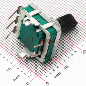
PEC16 - 16 mm Incremental Encoder
Electrical Characteristics
Output ................................................................................................................................................................................................................2-bit gray code Closed Circuit Resistance ..............................................................................................................................................................................3 ohms maximum Contact Rating ....................................................................................................................................................................................................1 mA @ 5 VDC Insulation Resistance ............................................................................................................................................................................10 megohms @ 50 VDC Dielectric Withstanding Voltage Sea Level ....................................................................................................................................................................................................50 VAC minimum Electrical Travel ........................................................................................................................................................................................................Continuous Contact Bounce (15 RPM) ..............................................................................................................................................................................5.0 ms. maximum RPM (Operating) ..................................................................................................................................................................................................100 maximum
Environmental Characteristics
Operating Temperature Range ..........................................................................................................................................-30 °C to +70 °C (-22 °F to +158 °F) Storage Temperature Range ............................................................................................................................................-40 °C to +85 °C (-40 °F to +185 °F) Humidity....................................................................................................................................................................MIL-STD-202, Method 103B, Condition B Vibration ..............................................................................................................................................................................................................................30 G Contact Bounce ..................................................................................................................................................10~55~10 Hz / 1 min. / Amplitude 1.5 mm Shock ................................................................................................................................................................................................................................100 G Rotational Life......................................................................................................................................................................................100,000 cycles minimum Switch Life ............................................................................................................................................................................................20,000 cycles minimum IP Rating ..............................................................................................................................................................................................................................IP 40
Mechanical Characteristics
Mechanical Angle ............................................................................................................................................................................................360 ° continuous Torque Running ......................................................................................................................................................................30.6 to 204 g-cm (0.42 to 2.83 oz.-in) Mounting ........................................................................................................................................................................10.2 kgf. cm (8.83 lb.-in.) maximum Shaft Side Load (Static) ..................................................................................................................................................................3.06 kgf (6.7 lbs.) minimum Weight ................................................................................................................................................................................................8 gm (0.28 oz.) maximum Terminals ....................................................................................................................................................................................Printed circuit board terminals Terminals ....................................................................................................................................................................................Printed circuit board terminals Soldering Condition Wave Soldering........................................................................................Sn95.5/Ag2.8/Cu0.7 solder with no-clean flux: 260 °C max. for 3-5 seconds Hand Soldering ....................................................................................................................................................................................Not recommended Hardware ........................................................................................................................One flat washer and one mounting nut supplied with each encoder.
Switch Characteristics
Switch Type ......................................................................................................................................................................Contact Push ON Momentary SPST Power Rating (Resistive Load) ........................................................................................................................................................................10 mA at 5 V DC Switch Travel....................................................................................................................................................................................................0.5 +0.4/-0.3 mm Switch Actuation Force ..................................................................................................................................................360 +153/-102 gf (5 +2.1/-1.4 oz.-in.)
How to Order
Quadrature Output Table
PEC16 - 4 0 20 F - S 0012
Model Terminal Configuration 2 = PC Pin Vertical/Down Facing 4 = PC Horizontal/Rear Facing Detent Option 0 = No Detents 1 = 12 Detents* (available with 12 pulses only) 2 = 24 Detents (available with 12 or 24 pulses) Standard Shaft Length 15 = 15 mm 20 = 20.0 mm 25 = 25.0 mm* 30 = 30.0 mm* Shaft Style F = Insulated Flatted Shaft Switch Configuration S = Push Momentary Switch N = No Switch Resolution 0012 = 12 Pulses per 360 ° Rotation 0024 = 24 Pulses per 360 ° Rotation * Not available with switch
CW
OFF A Signal B Signal D
ON
*RoHS Directive 2002/95/EC Jan 27 2003 including Annex Specifications are subject to change without notice. Customers should verify actual device performance in their specific applications.
�PEC16 - 16 mm Incremental Encoder
Product Dimensions
PEC16-2xxxF-Sxxxx
8.0 (.315) 7.5 (.295) L1 6 - D +0/-0.05 DIA. (6 - D +0/-.002) LB F 1.5 (.059)
6.0 (.236) DIA. 8.3 (.327)
16.0 (.630)
7.5 (.295) 3.1 (.122) 2.6 (.102) 9.3 (.366) 12.5 (.492) 14.4 (.567)
A
MOUNTING SURFACE 5.0 (.197)
12.5 (.492)
M9X0.75 (M9X.030)
4.5 +0/-0.05 (.177 +0/-0.02) 0.5 +0.1/-0.3 (.020 +.004/-.012)
9.0 (.354)
C
10.0 (.394)
3.5 ± 0.5 (.138 ± .020) 2.0 (.079)
3.1 (.122)
3.5 ± 0.5 (.138 ± .020) 2.0 (.079)
SWITCH TRAVEL
A
C
B
B
3.0 +0/-0.1 (118 ± .004) DIA. 5.0 (.197) 13.5 (.531) 16.1 (.634)
A CHANNEL A C COMMON B CHANNEL B
1.0 (.004) 4.0 (.157) 5.0 (.197)
2.0 (.079)
1.2 +0.1/-0 (.047 +.004/-0) DIA. 5 PLCS. 2.1 +0.1/-0 (.083 +.004/-0)
PEC16-4xxxF-Sxxxx
3.5 ± 0.5 (.138 ± .020) 16.8 (.661) 5.0 (.197)
A C B
8.0 (.315)
2.0 (.079)
L1 6 - D +0/-0.05 DIA. (6 - D +0/-.002) LB F 1.5 (.059)
8.3 (.327) 6.0 (.236) DIA. 16.0 (.630)
9.3 (.366) 2.0 (.079)
5.0 (.197)
4.5 (.177)
M9X0.75 (M9X.030) 0.5 +0.1/-0.3 (.020 +.004/-.012) 2.0 (.079)
4.5 +0/-0.05 (.177 +0/-0.02) 9.0 (.354) 3.0 +0/-0.1 (118 ± .004) DIA. 5.0 (.197) 17.7 (.697)
A CHANNEL A C COMMON B CHANNEL B
2.1 +0.1/-0 10.5 (.083 +.004/-0) (.413)
A C B
7.0 (.276)
3.5 ± 0.5 (.138 ± .020)
SWITCH TRAVEL
4.0 (.157) 12.5 (.492)
1.2 +0.1/-0 (.047 +.004/-0) DIA. 5 PLCS.
10.0 (.394)
L1 LB F
15.0 (.591) 5.0 (.197) 7.0 (.276)
20.0 (.787) 7.0 (.276) 12.0 (.472)
DIMENSIONS:
MM (INCHES)
Specifications are subject to change without notice. Customers should verify actual device performance in their specific applications.
�PEC16 - 16 mm Incremental Encoder
Product Dimensions
PEC16-2xxxF-Nxxxx
7.5 (.295) 6.5 (.256) L1 6 - D +0/-0.05 DIA. (6 - D +0/-.002) LB F 1.5 (.059)
6.0 (.236) DIA. 8.3 (.327)
16.0 (.630)
7.5 (.295) 3.1 (.122)
MOUNTING SURFACE
12.5 (.492)
M9X0.75 (M9X.030)
4.5 +0/-0.05 (.177 +0/-0.02)
9.0 (.354)
9.3 (.366) 12.5 (.492) 14.4 (.567)
A C
3.5 ± 0.5 (.138 ± .020) 2.0 (.079)
4.1 (.161)
3.5 ± 0.5 (.138 ± .020) 2.0 (.079)
A
C
B
B
3.0 +0/-0.1 (118 ± .004) DIA. 5.0 (.197) 13.5 (.531) 16.1 (.634)
A CHANNEL A C COMMON B CHANNEL B
1.0 (.004) 4.0 (.157) 5.0 (.197)
2.0 (.079)
1.2 +0.1/-0 (.047 +.004/-0) DIA. 3 PLCS. 2.1 +0.1/-0 (.083 +.004/-0)
PEC16-4xxxF-Nxxxx
6.5 (.256) 3.5 ± 0.5 (.138 ± .020) 2.0 (.079)
L1 6 - D +0/-0.05 DIA. (6 - D +0/-.002) LB F 1.5 (.059) 6.0 (.236) DIA.
8.3 (.327) 16.0 (.630)
9.3 (.366) 5.0 (.197)
A C B
2.0 (.079)
16.8 (.661)
2.1 +0.1/-0 10.5 (.083 +.004/-0) (.413)
A C
4.5 (.177) 2.7 (.106)
B
M9X0.75 (M9X.030) 4.5 +0/-0.05 2.0 (.177 +0/-0.02) (.079) 3.5 ± 0.5 (.138 ± .020)
9.0 (.354) 3.0 +0/-0.1 (118 ± .004) DIA.
4.0 (.157) 12.5 (.492)
5.0 (.197) 17.7 (.697)
A CHANNEL A C COMMON B CHANNEL B
1.2 +0.1/-0 (.047 +.004/-0) DIA. 3 PLCS.
10.0 (.394)
L1 LB F
15.0 (.591) 5.0 (.197) 7.0 (.276)
20.0 (.787) 7.0 (.276) 12.0 (.472)
DIMENSIONS:
MM (INCHES)
REV. 07/07 Specifications are subject to change without notice. Customers should verify actual device performance in their specific applications.
�
很抱歉,暂时无法提供与“PEC16-4220F-N0012”相匹配的价格&库存,您可以联系我们找货
免费人工找货- 国内价格
- 1+15.44428
- 10+14.04025
- 30+13.10423
- 100+11.70021
- 500+11.045
- 1000+10.57699


 工商网监
湘ICP备2023018690号
工商网监
湘ICP备2023018690号

