T
PL
IA
N
M
Features
■ Compact design, long life and high
*R
oH
S
CO
reliability
■ Vertical and horizontal mount versions
■ Momentary switch
■ Dual LED design
■ Flatted and knurled shaft styles
■ Bushing and bushingless options
PEL12D - 12 mm Encoder with Switch and Illuminated Shaft
Electrical Characteristics
Output .....................................................................................................................................................................................2-bit quadrature code
Closed Circuit Resistance ........................................................................................................................................................... 3 ohms maximum
Contact Rating .............................................................................................................................................................................. 0.5 mA @ 5 VDC
Insulation Resistance ....................................................................................................................................................100 megohms @ 250 VDC
Dielectric Withstanding Voltage
Sea Level ................................................................................................................................................................................ 300 VAC minimum
Electrical Travel ......................................................................................................................................................................................Continuous
Contact Bounce (15 RPM).........................................................................................................................................................2.0 ms. maximum**
RPM (Operating) ............................................................................................................................................................................ 100 maximum**
Environmental Characteristics
Operating Temperature Range .......................................................................................................................-10 °C to +70 °C (+14 °F to +158 °F)
Storage Temperature Range .......................................................................................................................... -40 °C to +85 °C (-40 °F to +185 °F)
Operating Humidity ..................................................................................................................................................................... 25 % to 85 % R.H.
Rotational Life..................................................................................................................................................................... 30,000 cycles minimum
Switch Life .......................................................................................................................................................................... 20,000 cycles minimum
IP Rating ...........................................................................................................................................................................................................IP 40
Mechanical Characteristics
Mechanical Angle .......................................................................................................................................................................... 360 ° continuous
Detent Torque ..................................................................................................................................................30 to 200 g-cm (0.42 to 2.77 oz.-in.)
Running Torque ..................................................................................................................................................... 50 g-cm (0.69 oz.-in.) maximum
Shaft Strength (Push) ...................................................................................................................................................................... 5 kgf (11.0 lbs.)
Shaft Strength (Pull) ...................................................................................................................................................................... 10 kgf (22.0 lbs.)
Weight ............................................................................................................................................................................... 3 gm (0.1 oz.) maximum
Terminals .................................................................................................................................................................. Printed circuit board terminals
Soldering Condition
Wave Soldering ..................................................................... Sn95.5/Ag2.8/Cu0.7 solder with no-clean flux: 260 °C max. for 5 ± 1 seconds
Hand Soldering .................................................................................................................................................................. Not recommended
Hardware ................................................................................... One flat washer and one mounting nut supplied with each encoder with bushing
Switch Characteristics
Switch Type .....................................................................................................................................................Contact Push ON Momentary SPST
Power Rating (Resistive Load) ...................................................................................................................................................... 10 mA at 5 V DC
Contact Resistance ............................................................................................................................................................................100 milliohms
Switch Travel .................................................................................................................................................................................0.5 +0.0/-0.3 mm
Switch Actuation Force .................................................................................................................................................450 ± 200 gf (15.9 ±7.0 oz.)
How To Order
PEL12D - 4 0 21 F - S 1 024
Model
Terminal Configuration
2 = Vertical Mount/Side Exit PC Pin
4 = Horizontal Mount/Rear Exit PC Pin
Detent Option
0 = No Detents
2 = 24 Detents
Standard Shaft Length
Flatted:
Knurled:
16 = 16.0 mm
26 = 26.0 mm
25 = 25.0 mm
18 = 18.5 mm
31 = 31.0 mm
21 = 21.0 mm
Shaft Style
F = Insulated Flatted Shaft
S = Insulated Knurled Shaft (18 Teeth)
G = Insulated Flatted Shaft w/Bushing***
T = Insulated Knurled Shaft (18 Teeth) w/Bushing
Switch Configuration
S = Push Momentary Switch
LED Color
Dual:
1 = Blue/Orange
2 = Green/Red
3 = Blue/Green
Resolution
024 = 24 Pulses per 360 ° Rotation
*RoHS Directive 2015/863, Mar 31, 2015 and Annex.
*** Available in 18.5, 21 and 26 mm shaft lengths
**Devices are tested using standard noise reduction filters.
WARNING
Cancer and Reproductive Harm
www.P65Warnings.ca.gov
For optimum performance, designers should use noise reduction filters in their circuits.
Specifications are subject to change without notice. Users should verify actual device performance in their specific applications.
The products described herein and this document are subject to specific legal disclaimers
as set forth on the last page of this document, and at www.bourns.com/docs/legal/disclaimer.pdf.
�Applications
Level control, tuning and timer settings in:
■ Audio-visual equipment
■ Consumer electric appliances
■ Musical instrumentation
■ Communications equipment
PEL12D - 12 mm Encoder with Switch and Illuminated Shaft
Product Dimensions
PEL12D-4xxxS-Sxxxx (Horizontal Mount w/Dual LED & Switch, Knurled Shaft)
MOUNTING
SURFACE
25.0
(.984)
7.0
(.276)
4 PLCS.
0.8
(.031)
0.3
(.012)
2.9
(.114)
14.0
(.551)
18.0
(.709)
5.0
(.197)
0.8
(.031)
7.0
(.276)
SWITCH
STROKE
0.5 +0/-0.3
(.020 +0/-.012)
2.0 ± 0.1
(.079 ± .004)
18 TEETH
0.3
(.012)
13.2 ± 0.1
(.520 ± .004)
12.4
(.488)
13.2
(.520)
10.2
(.402)
2.8
(.110)
1.0 +0.2/-0
(.039 +.008/-0)
DIA. 4 PLCS.
4
7.0 ± 0.1
(.276 ± .004)
3
2
2 PLCS.
2.1 +0.1/-0
(.083 +.004/-0)
1
7.5 ± 0.1
(.295 ± .004)
6.0
(.236)
DIA.
6.8
DIA.
(.268)
6.0 ± 0.1
(.236 ± .004)
2.0 ± 0.1
(.079 ± .004)
8.2
(.323)
A
C
2.0 +0.1/-0
(.079 +.004/-0)
2 PLCS.
B
5.0 ± 0.1
(.197 ± .004)
5.0
(.197)
A
C
B
1.1 +0.2/-0
(.043 +.008/-0)
DIA. 3 PLCS.
PEL12D-4xxxF-Sxxxx (Horizontal Mount w/Dual LED & Switch, Flatted Shaft)
MOUNTING
SURFACE
LM
7.0
(.276)
0.3
(.012)
2.9
(.114)
0.8
(.031)
L1
1.5
5.0
(.197) (.591)
SWITCH
STROKE
0.5 +0/-0.3
(.020 +0/-.012)
14.0
(.551)
L1
LM
12.4
(.488)
3
(.118)
16
(.630)
5
(.197)
18.5
(.728)
7
(.276)
21
(.827)
12
(.472)
26
(1.024)
12
(.472)
31
(1.220)
8.2
(.323)
0.5
(.020)
2.0 ± 0.1
(.079 ± .004)
13.2
(.520)
10.2
(.402)
0.3
(.012)
2.8
(.110)
6.8
(.268)
DIA.
4.5 ± 0.05
(.177 ± .002)
DIA.
6.0 ± 0.1
(.236 ± .004)
A
C
B
5.0
(.197)
DIMENSIONS:
Dual LED Circuit
UNDER
MM
(INCHES)
TOLERANCES:
10.0
±0.3
±0.5
10.0 ~ 100
=
=
(.394) (±.012) (.394 ~ 3.937) (±.020)
4
(+) 3
(+) 2
(-) 1
Specifications are subject to change without notice.
Users should verify actual device performance in their specific applications.
The products described herein and this document are subject to specific legal disclaimers as set forth on the last page of this document, and at www.bourns.com/docs/legal/disclaimer.pdf.
�PEL12D - 12 mm Encoder with Switch and Illuminated Shaft
Product Dimensions
PEL12D-2xxxS-Sxxxx (Vertical Mount w/Dual LED & Switch, Knurled Shaft)
MOUNTING
SURFACE
25.0
(.984)
7.0
(.276)
2.5
(.098)
18.0
(.709)
5.0
(.197)
0.8
(.031)
7.0
(.276)
SWITCH
STROKE
0.5 +0/-0.3
(.020 +0/-.012)
18 TEETH
10.0
(.394)
4 PLCS.
0.8
(.031)
4.5 ± 0.1
(.177 ± .004)
12.4
(.488)
8.2
(.315)
6.0 ± 0.1
(.236 ± .004)
13.2
(.520)
10.2
(.402)
1.0 +0.2/-0
(.039 +.008/-0)
DIA. 4 PLCS.
5.0 ± 0.1
(.197 ± .004)
B
4
10.8 ± 0.1
(.425 ± .004)
3
2
6.0
(.236)
DIA.
6.8
DIA.
(.268)
3.1 ± 0.1
(.122 ± .004)
2.0 +0.1/-0
(.079 +.004/-0)
2 PLCS.
C
A
1
1.1 +0.2/-0
(.043 +.008/-0)
DIA. 3 PLCS.
2.0 ± 0.1
(.079 ± .004)
3.5
(.138)
A
C
B
2.0 +0.1/-0
(.079 +.004/-0)
2 PLCS.
10.0
(.394)
2.0
(.079)
6.1
(.240)
2.1 +0.1/-0
(.083 +.004/-0)
2 PLCS.
PEL12D-2xxxF-Sxxxx (Vertical Mount w/Dual LED & Switch, Flatted Shaft)
MOUNTING
SURFACE
LM
7.0
(.276)
2.5
(.098)
12.4
(.488)
L1
1.5
5.0
(.197) (.591)
0.8
(.031)
SWITCH
STROKE
0.5 +0/-0.3
(.020 +0/-.012)
8.2
(.315)
0.5
(.020)
13.2
(.520)
10.2
(.402)
10.0
(.394)
6.8
(.268)
DIA.
4.5 ± 0.05
(.177 ± .002)
DIA.
6.0 ± 0.1
(.236 ± .004)
3.5
(.138)
2.0
(.079)
A
C
L1
LM
3
(.118)
16
(.630)
5
(.197)
18.5
(.728)
7
(.276)
21
(.827)
12
(.472)
26
(1.024)
12
(.472)
31
(1.220)
B
10.0
(.394)
6.1
(.240)
DIMENSIONS:
UNDER
MM
(INCHES)
TOLERANCES:
10.0
±0.3
±0.5
10.0 ~ 100
=
=
(.394) (±.012) (.394 ~ 3.937) (±.020)
Specifications are subject to change without notice.
Users should verify actual device performance in their specific applications.
The products described herein and this document are subject to specific legal disclaimers as set forth on the last page of this document, and at www.bourns.com/docs/legal/disclaimer.pdf.
�PEL12D - 12 mm Encoder with Switch and Illuminated Shaft
Product Dimensions
Quadrature Output Table
CW
PEL12D-4xxxT-Sxxxx (Horizontal Mount w/Dual LED & Switch, Knurled Shaft w/Bushing)
25.0
(.984)
7.5
(.295)
OFF
17.5
(.689)
7.0
(.276)
A Signal
7.0
(.276)
0.3
(.012)
ON
B Signal
D
CCW
18 TEETH
M9 X
Suggested Filter Circuit
6.0
DIA.
(.236)
0.75
(.030)
5 VDC
PEL12D-4xxxG-Sxxxx (Horizontal Mount w/Dual LED & Switch, Flatted Shaft w/Bushing)
10K OHMS
1 0K OH MS
LM
L2
L1
LM
TERMINAL A
5
(.197)
11
(.433)
18.5
(.728)
0.01 μF
7
(.276)
13.5
(.532)
21
(.827)
12
(.472)
18.5
(.728)
26
(1.024)
L1
5.0
(.199)
L2
0.75
M9 X
(.030)
DIMENSIONS:
UNDER
10K OHMS
MM
(INCHES)
TOLERANCES:
10.0
±0.3
±0.5
10.0 ~ 100
=
=
(.394) (±.012) (.394 ~ 3.937) (±.020)
10K OHMS
TERMINAL B
0.01 μF
ENCODER
TERMINAL C
LED Terminal Decoder
Code
Color
Terminals
1
Blue / Orange
2
Green / Red
3
Blue / Green
➀➁ / ➀➂
➀➁ / ➀➂
➀➁ / ➀➂
LED Characteristics (Dual)
LED Color
Power
Dissipation
(mW)
DC
Forward
Current
(mA)
Forward Voltage (V)
Typ.
Max.
Blue/
Orange
Blue
105
30
3.3
4.0
Orange
75
30
2.1
2.5
Green/
Red
Green
120
30
3.2
4.0
Red
75
30
1.95
2.5
Blue/
Green
Blue
120
30
3.3
4.0
Green
120
30
3.2
4.0
Red/
Green
Red
75
30
1.95
2.5
Green
120
30
3.2
4.0
Asia-Pacific:
Tel: +886-2 2562-4117
Email: asiacus@bourns.com
Europe:
Tel: +36 88 885 877
Email: eurocus@bourns.com
The Americas:
Tel: +1-951 781-5500
Email: americus@bourns.com
www.bourns.com
Notes:
Reverse Current:
10 μA
Reverse Voltage:
5 VDC
Test Condition (IF): 20 mA
Specifications are subject to change without notice.
REV. 09/19
Users should verify actual device performance in their specific applications.
The products described herein and this document are subject to specific legal disclaimers as set forth on the last page of this document, and at www.bourns.com/docs/legal/disclaimer.pdf.
�Legal Disclaimer Notice
This legal disclaimer applies to purchasers and users of Bourns® products manufactured by or on behalf of Bourns, Inc. and
P[Z�HɉSPH[LZ��JVSSLJ[P]LS`��¸)V\YUZ¹��
Unless otherwise expressly indicated in writing, Bourns® products and data sheets relating thereto are subject to change
^P[OV\[�UV[PJL���
很抱歉,暂时无法提供与“PEL12D-4225T-S3024”相匹配的价格&库存,您可以联系我们找货
免费人工找货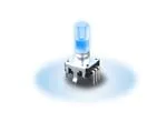


 工商网监
湘ICP备2023018690号
工商网监
湘ICP备2023018690号
