PL
IA
NT
Features
Applications
CO
M
■ Formerly
model
■ Prevention of electromagnetic interference
to signals on the secondary side of
electronic equipment
*R
oH
S
■ Magnetic shielding
■ High Q characteristic
■ High current rating
■ RoHS compliant*
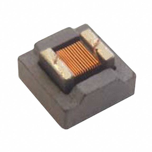
PM1008S Series - Shielded Wirewound Chip Inductors
Electrical Specifications
Bourns Part No.
Inductance
μH
(@100 KHz)
Tolerance
%
Q min.
(@ 1 MHz)
SRF
MHz
min.
DCR
Ω
max.
Idc
mA
max.
PM1008S-1R0M-RC
1.0
±20
35
344
0.05
3000
PM1008S-1R5M-RC
1.5
±20
35
260
0.06
2800
PM1008S-1R8M-RC
1.8
±20
35
225
0.09
2000
PM1008S-2R7M-RC
2.7
±20
38
185
0.14
1300
PM1008S-3R9M-RC
3.9
±20
38
175
0.26
1200
PM1008S-4R7M-RC
4.7
±20
38
160
0.35
1000
PM1008S-5R6M-RC
5.6
±20
38
150
0.40
1000
PM1008S-6R8M-RC
6.8
±20
38
120
0.60
850
PM1008S-100M-RC
10
±20
38
105
1.0
780
PM1008S-150M-RC
15
±20
38
35
1.2
700
PM1008S-220M-RC
22
±20
40
26
1.4
650
PM1008S-330M-RC
33
±20
45
20
1.6
500
PM1008S-390M-RC
39
±20
45
16
1.9
450
PM1008S-470M-RC
47
±20
45
14
2.5
400
PM1008S-680M-RC
68
±20
45
12
3.8
300
PM1008S-820M-RC
82
±20
45
9
4.2
280
PM1008S-101M-RC
100
±20
45
7
5.8
260
PM1008S-121M-RC
120
±20
50
6
6.2
250
PM1008S-151M-RC
150
±20
50
5.6
7.5
220
PM1008S-221M-RC
220
±20
55
4.5
10.0
210
PM1008S-331M-RC
330
±20
55
3.8
11.5
200
PM1008S-471M-RC
470
±20
55
3.0
16.5
160
PM1008S-561M-RC
560
±20
55
2.8
18.0
130
PM1008S-681M-RC
680
±20
55
2.5
24.0
120
PM1008S-821M-RC
820
±20
45
1.5
26.0
100
PM1008S-102M-RC
1000
±20
45
1.3
30.0
100
General Specifications
Current Rating
............10 % drop in inductance at Idc
Temperature Rise
................. 15 °C max. at rated current
Operating Temperature
.................................. -40 °C to +85 °C
Storage Temperature .....-40 °C to +85 °C
Reflow Soldering ....230 °C; 50 sec max.
Resistance to Soldering Heat
.............................260 °C, 5 sec. max.
Materials
Core Material ................................Ferrite
Terminal Electrode ..........................Sn/Ni
Packaging .....................750 pcs. per reel
Product Dimensions
2.74
(.108)
MAX.
2.54
(.100)
MAX.
3.81
(.150)
MAX.
2.11
MAX.
(.083)
3.81
(.150)
MAX.
Recommended Pad Layout
1.27
REF.
(.050)
REF.
2.54
(.100)
1.02
REF.
(.040)
DIMENSIONS:
WARNING Cancer and Reproductive Harm - www.P65Warnings.ca.gov
* RoHS Directive 2002/95/EC Jan. 27, 2003 including annex and RoHS Recast 2011/65/EU June 8, 2011.
Specifications are subject to change without notice. Users should verify actual device performance in their specific
applications. The products described herein and this document are subject to specific legal disclaimers as set forth on
the last page of this document, and at www.bourns.com/docs/legal/disclaimer.pdf
MM
(INCHES)
�PM1008S Series - Shielded Wirewound Chip Inductors
Packaging Specifications
2.00
(.079)
178.00
(7.008)
DIA.
DIMENSIONS:
75.00
DIA.
(2.953)
MM
(INCHES)
21.00
DIA.
(.827)
2.50
(.098)
DIA.
END
14.00
(.551)
2.00
(.079)
1.50
(.059)
START
4.0
(.157)
1.75
(.069)
12.00
(.472)
5.50
(.217)
3.8
(.150)
8.00
(.315)
NO COMPONENT
80.00
(3.150)
0.30
(.012)
4.00
(.157)
2.50
(.098)
NO COMPONENT
COMPONENTS
160.00
(6.299)
USER DIRECTION OF FEED
QTY: 750 PCS. PER REEL
Tel: +886-2 2562-4117 • Email: asiacus@bourns.com
EMEA: Tel: +36 88 520 390 • Email: eurocus@bourns.com
The Americas: Tel: +1-951 781-5500 • Email: americus@bourns.com
www.bourns.com
01/08
Specifications are subject to change without notice.
Users should verify actual device performance in their specific applications.
The products described herein and this document are subject to specific legal disclaimers as set forth on the last page of this document, and at www.bourns.com/docs/legal/disclaimer.pdf.
�Legal Disclaimer Notice
This legal disclaimer applies to purchasers and users of Bourns® products manufactured by or on behalf of Bourns, Inc. and
P[Z�HɉSPH[LZ��JVSSLJ[P]LS`��¸)V\YUZ¹��
Unless otherwise expressly indicated in writing, Bourns® products and data sheets relating thereto are subject to change
^P[OV\[�UV[PJL���
很抱歉,暂时无法提供与“PM1008S-1R8M-RC”相匹配的价格&库存,您可以联系我们找货
免费人工找货