T
PL
IA
N
M
CO
*R
oH
S
Features
■ Carbon element
■ Assortment of resistance tapers
■ Dual gang element
■ Center detent option
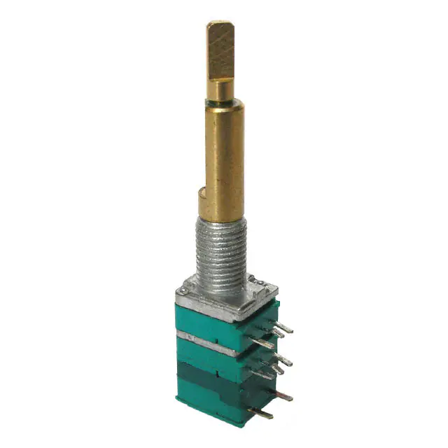
PTJ90 Series Dual Concentric Shaft Panel Control w/Push-Push Switch
Electrical Characteristics
Standard Resistance Range
............................1K ohms to 1 megohm
Standard Resistance Tolerance
R < 250K ohms .............................±20 %
R ≥ 250K ohms .............................±30 %
End Resistance
R < 50K ohms .................. 30 ohms max.
R ≥ 50K ohms ............. 0.1 % of TR max.
Insulation Resistance @ 250 VDC
................................. 100 megohms min.
Dielectric Withstanding Voltage ....300 VAC
Standard Taper ...................... Linear, Audio
Power Rating
Linear ....................................... 0.05 watt
Audio ...................................... 0.025 watt
Slider Noise ...........................100 mV max.
Operating Voltage ........... 50 VAC / 10 VDC
Product Dimensions
PTJ902-xxxF
25.8
(1.016)
30.0 ± 1.0
(1.181 ± 0.039)
SWITCH TRAVEL
1.5 ± 0.5
(0.059 ± 0.020)
8.2
(0.323)
20.0
(0.787)
10.0
8.5
(0.394)
(0.335)
7.0
(0.276)
60 °
3.5 +0/-0.05
(0.138 +0/-0.002)
DIA.
9.5
(0.374)
4.85
(0.191)
Y
X
0.75
(0.030)
C0.5
5.0 + 0/-0.1
2.5 +0/-0.1
(0.197 +0/-0.004)
0.8 ± 0.2
(0.098 +0/-0.004)
6.0 + 0/-0.05
(0.031 ± 0.002)
(0.236 +0/-0.002)
DIA.
M9 x
R2
R1
6.5 ± 0.5
(0.256 ± 0.002)
Y
0.9 ± 0.1
(0.035 ± 0.004)
25.8
(1.016)
Operational Life .................... 15,000 cycles
TR Shift .........................................±15 %
Operating Temperature Range
......................................-10 °C to +55 °C
Resistance to Solder Heat ..................±5 %
IP Rating .............................................IP 40
3.5
(0.138)
INNER AND OUTER SHAFT
SHOWN IN CCW POSITION
PTJ902-xxxS
Environmental Characteristics
X
30.0 ± 1.0
(1.181 ± 0.039)
20.0
(0.787)
SWITCH TRAVEL
1.5 ± 0.5
(0.059 ± 0.020)
8.0
(0.315)
5.0
(0.197)
60 °
6.7 + 0/-0.05
(0.264 +0/-0.002)
DIA.
10.0
(0.394)
Y
9.5
(0.374)
4.85
(0.191)
X
X
Mechanical Characteristics
Mechanical Angle ....................... 300 ° ±3 °
Operating Torque ..................20~250 gf-cm
Stop Strength....................... 5 kgf-cm max.
Mounting Torque ................ 10 kgf-cm max.
Shaft Push/Pull Strength ......... 10 kgf max.
Soldering Condition
Manual ............... 300 °C ±5 °C for 3 sec.
Wave .................. 260 °C ±5 °C for 5 sec.
Wash ......................... Not recommended
Hardware ....................One flat washer and
one mounting nut supplied with
each potentiometer
Switch Characteristics
Power Rating .......................3 A @ 16 VDC
Contact Resistance .............. 100 milliohms
Dielectric Strength
Bushing to Terminals.................300 VAC
Switch Terminals .........................50 VAC
Insulation Resistance
Bushing to Terminals @ 250 VAC
......................................... 100 megohms
Switch Terminals @ 50 VAC
........................................... 10 megohms
Switch Type .................. Push on - Push off
Contact Arrangement........................ SPDT
Switch Stroke......................... 1.5 ± 0.1 mm
Operating Force......................... 2 kgf max.
Operating Life ....................... 10,000 cycles
R2
C0.5
M9 x
0.75
(0.030)
R1
1.5 ± 0.1
(0.059 ± 0.004)
www.P65Warnings.ca.gov
6.5 ± 0.5
(0.256 ± 0.002)
3.0 +0.1/-0
(.118 +0.004/-0)
0.9 ± 0.1
3.5
(0.035 ± 0.004) (0.138)
DIMENSIONS:
Mounting Hole Detail
A
C
D
F
INNER AND OUTER SHAFT
SHOWN IN CCW POSITION
Y
5.0
(0.197)
6.8
(0.268)
4.0
(0.157)
MM
(INCHES)
Locating Lug Detail
X
5.0
(0.197)
X
MOUNTING
SURFACE
DIA.
1.0 +0.1/-0
(0.039 +0.004/-0)
10 PLCS.
5.0
(0.197)
Y
6.0 ± 0.2
(0.236 ± 0.008)
0.8 ± 0.2
(0.315 ± 0.008)
2.0 ± 0.1
(0.079 ± 0.004)
Hardware
DIA.
12.0
(.472)
7.2
DIA.
(.283)
M7 x 0.75
(.030)
DIA.
12.7
(.500)
11.0
(.433)
DIA.
NUT
WARNING Cancer and Reproductive Harm
4.7 + 0/-0.05
(0.185 +0/-0.002)
DIA.
0.5
(.020)
2.0
(.079)
WASHER
*RoHS Directive 2015/863, Mar 31, 2015 and Annex.
Specifications are subject to change without notice. Users should verify actual device performance in their specific
applications. The products described herein and this document are subject to specific legal disclaimers as set forth on the
last page of this document, and at www.bourns.com/docs/legal/disclaimer.pdf.
�Applications
■ Multimedia sound systems
■ Mixers / drums / DJ equipment
■ Portable electronics
■ Portable appliances
PTJ90 Series Dual Concentric Shaft Panel Control w/Push-Push Switch
Schematic
Model Number
Designator
PTJ90 = Dual
Concentric Shaft Panel
Control w/Push-Push
Switch
Number of Sections
2 = Dual Gang
Center Detent
0 = No Detent
1 = Center Detent
Shaft Length (FMS)
30 = 30 mm
Shaft Style
F = Flatted Metal
S = Slotted Metal
Resistance Code
(See Standard Resistance Table)
Resistance Taper (See Taper Charts)
Taper Series followed by Curve Number
Standard Resistance Table
Resistance
(Ohms)
1,000
2,000
5,000
10,000
20,000
50,000
100,000
200,000
500,000
1,000,000
Resistance
Code
102
202
502
103
203
503
104
204
504
105
40
6
);A
0A
(3
30
A5
A);
(25
4
A);A
3
(20
A);A
(15
0A);A2
20
10
(1
0
10
20
30
1
A);A
(05
40
50
60
70
80
Rotational Travel (%)
Terminal 1
90
100
Terminal 3
B Series Tapers
100
;B5
)
(5B
90
80
B)
;B
2
PTJ90 2 - 0 30 F - 103 B2
60
50
(2
How To Order
70
;B
1
2'
90
80
B)
3'
(1
3
R2 1'
(4B
);B
4
R1 1
3
F
A Series Tapers
100
);B
D
OUTER
CONNECTION
2
(3B
C
Tapers
Output Voltage across Terminals 1-2
X 100 (%)
Input Voltage across Terminals 1-3
A
Dual Gang
Output Voltage across Terminals 1-2
X 100 (%)
Input Voltage across Terminals 1-3
Switch Circuit
70
60
50
40
30
20
10
0
10
20
30
40
50
60
70
80
Rotational Travel (%)
Terminal 1
90
100
Terminal 3
C Series Tapers
100
Asia-Pacific: Tel: +886-2 2562-4117 • Email: asiacus@bourns.com
EMEA: Tel: +36 88 885 877 • Email: eurocus@bourns.com
The Americas: Tel: +1-951 781-5500 • Email: americus@bourns.com
www.bourns.com
Output Voltage across Terminals 1-2
X 100 (%)
Input Voltage across Terminals 1-3
90
80
70
60
50
40
(3
0C
(25
C)
;C5
30
);C
6
(20
20
(1
10
0C
);C
2
0
10
20
30
40
4
);C
(05
C);C
1
Terminal 1
C);C
(15
C
50
3
60
Rotational Travel (%)
70
80
90
100
Terminal 3
REV. 10/19
Specifications are subject to change without notice.
Users should verify actual device performance in their specific applications.
The products described herein and this document are subject to specific legal disclaimers as set forth on the last page of this document, and at www.bourns.com/docs/legal/disclaimer.pdf.
�Legal Disclaimer Notice
This legal disclaimer applies to purchasers and users of Bourns® products manufactured by or on behalf of Bourns, Inc. and
P[Z�HɉSPH[LZ��JVSSLJ[P]LS`��¸)V\YUZ¹��
Unless otherwise expressly indicated in writing, Bourns® products and data sheets relating thereto are subject to change
^P[OV\[�UV[PJL���
很抱歉,暂时无法提供与“PTJ902-030F-103B1”相匹配的价格&库存,您可以联系我们找货
免费人工找货