R50E12.pdf 02.9.5
catalog
to prevent
smoking
and/or
burning,
Pleaseread
readrating
ratingand
and!CAUTION
!CAUTION(for
(forstorage
storageand
andoperating,
operating,rating,
rating,soldering
solderingand
andmounting,
mounting,handling)
handling)ininthis
thisPDF
catalog
to prevent
smoking
and/or
burning,
etc. etc.
!Note •Please
you are
requested
approvespecifications.
our product specification
or to transact
theour
approval
for product
specificaion
before ordering.
•This
Thiscatalog
cataloghas
hasonly
onlytypical
typicalspecifications.
specificationsTherefore,
because there
is no
space fortodetailed
Therefore, please
approve
productsheet
specification
or transact
the approval
sheet for product specification before ordering.
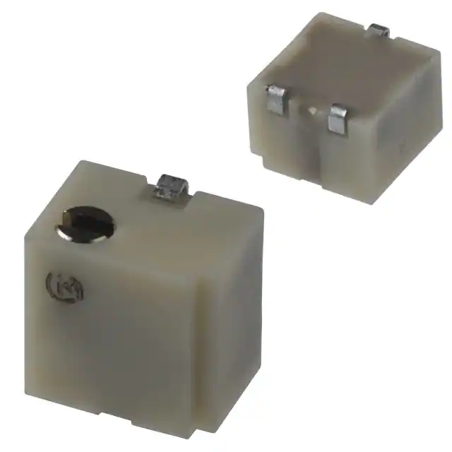
Trimmer Potentiometers
SMD Sealed Type Multi-turn Type PVG5/PV01 Series
4.8
PVG5 Series
■ Features
ADJ. Slot
DIA 1.5
Width 0.6
Depth 0.5
5.0
3-0.9
#2
0.5
3.9
2.6
3-0.7
3-0.8
2.4
1.2
3.5
1. High resolution resulting from 11-turns design
enables precise adjustment.
2. 5mm miniature size lead a high density PCB mounting.
3. Compatible with VPS reflow soldering method.
4. Compatible with ultrasonic cleaning.
5. Clutch mechanism prevents excessive wiper rotation.
#3
0.2
#1
2.5
Schematic
#2
■ Applications
PVG5A
1. Measuring instruments
2. sensors
3. CPUs
4. Industrial machines
#1
#3
CLOCKWISE
4.8
2.4
4.9
3-0.8
2.6
3.7
1.2
0.5
ADJ.Slot
DIA 1.5
Width 0.6
Depth 0.5
mm
(Tolerancein: ±0.3
)
3-0.7
3-0.9
#3
Schematic
2.3
#2
#2
PVG5H
#1
#1
#3
CLOCKWISE
mm
(Tolerancein: ±0.3
)
Power Rating
(W)
Soldering Method
Number of Turns
(Effective Rotation Angle)
Total Resistance Value
TCR
(ppm/°C)
PVG5p100A01
0.25(70°C)
Reflow
11
10ohm ±10%
±200
PVG5p200A01
0.25(70°C)
Reflow
11
20ohm ±10%
±200
PVG5p500A01
0.25(70°C)
Reflow
11
50ohm ±10%
±200
PVG5p101A01
0.25(70°C)
Reflow
11
100ohm ±10%
±200
PVG5p201A01
0.25(70°C)
Reflow
11
200ohm ±10%
±100
PVG5p501A01
0.25(70°C)
Reflow
11
500ohm ±10%
±100
PVG5p102A01
0.25(70°C)
Reflow
11
1k ohm ±10%
±100
PVG5p202A01
0.25(70°C)
Reflow
11
2k ohm ±10%
±100
PVG5p502A01
0.25(70°C)
Reflow
11
5k ohm ±10%
±100
PVG5p103A01
0.25(70°C)
Reflow
11
10k ohm ±10%
±100
PVG5p203A01
0.25(70°C)
Reflow
11
20k ohm ±10%
±100
PVG5p503A01
0.25(70°C)
Reflow
11
50k ohm ±10%
±100
PVG5p104A01
0.25(70°C)
Reflow
11
100k ohm ±10%
±100
PVG5p204A01
0.25(70°C)
Reflow
11
200k ohm ±10%
±100
PVG5p504A01
0.25(70°C)
Reflow
11
500k ohm ±10%
±100
PVG5p105A01
0.25(70°C)
Reflow
11
1M ohm ±10%
±100
PVG5p205A01
0.25(70°C)
Reflow
11
2M ohm ±10%
±100
Part Number
The blank column is filled with the code of adjustment direction A (top) or H (side).
33
6
�R50E12.pdf 02.9.5
catalog
to prevent
smoking
and/or
burning,
Pleaseread
readrating
ratingand
and!CAUTION
!CAUTION(for
(forstorage
storageand
andoperating,
operating,rating,
rating,soldering
solderingand
andmounting,
mounting,handling)
handling)ininthis
thisPDF
catalog
to prevent
smoking
and/or
burning,
etc. etc.
!Note •Please
you are
requested
approvespecifications.
our product specification
or to transact
theour
approval
for product
specificaion
before ordering.
•This
Thiscatalog
cataloghas
hasonly
onlytypical
typicalspecifications.
specificationsTherefore,
because there
is no
space fortodetailed
Therefore, please
approve
productsheet
specification
or transact
the approval
sheet for product specification before ordering.
■ Construction
Adjustment Screw
Gear
Case
#2 Terminal
Wiper
Resistive Element
#1, #3 Terminal
Ceramic Substrate
■ Standard Land Pattern
PVG5A
PVG5H
1.6
2.25
1.2
1.3
1.3
mm
(Tolerance in: ±0.1
)
■ Characteristics
6
Temperature Cycle
Humidity
Vibration
Shock
∆TR
±2%
∆V.S.S.
±1%
∆TR
±2%
IR
10Mohm min.
∆TR
±1%
∆V.S.S.
±1%
∆TR
±1%
∆V.S.S.
±1%
∆TR
±3% or 3ohm max.,
Temperature Load Life
Low Tamperature Exposure
High Tamperature Exposure
Rotational Life (100 cycles)
whichever is greater
∆V.S.S.
±1%
∆TR
±1%
∆V.S.S.
±1%
∆TR
±2%
∆V.S.S.
±1%
∆TR
±3% or 3ohm max.,
whichever is greater
∆TR
: Total Resistance Change
∆V.S.S. : Voltage Setting Stability
IR
: Insulation Resistance
34
2.8
1.6
2.25
1.6
1.6
1.3
2.8
1.3
1.3
1.0
1.3
mm
(Tolerancein: ±0.1
)
�R50E12.pdf 02.9.5
catalog
to prevent
smoking
and/or
burning,
Pleaseread
readrating
ratingand
and!CAUTION
!CAUTION(for
(forstorage
storageand
andoperating,
operating,rating,
rating,soldering
solderingand
andmounting,
mounting,handling)
handling)ininthis
thisPDF
catalog
to prevent
smoking
and/or
burning,
etc. etc.
!Note •Please
you are
requested
approvespecifications.
our product specification
or to transact
theour
approval
for product
specificaion
before ordering.
•This
Thiscatalog
cataloghas
hasonly
onlytypical
typicalspecifications.
specificationsTherefore,
because there
is no
space fortodetailed
Therefore, please
approve
productsheet
specification
or transact
the approval
sheet for product specification before ordering.
PV01 Series
6.4
1.8±0.2 DIA
3−1.0
4.0
1. High resolution, resulting from 12-turns design
enables precise adjustment.
2. Compatible with VPS reflow soldering method.
3. Small size. (6.35x6.35x4.3mm)
4. Compatible with ultrasonic cleaning.
5. Clutch mechanism prevents excessive wiper rotation.
0.6±0.2
6.7
0.6
1.0
#2
3−0.4±0.1 Dia.
#1
#3
2.5
2.5
#2
■ Applications
1. Measuring instruments
3. CPUs
5. Printers
1.2
1.1
■ Features
PV01P
#1
2. Facsimile machines
4. PPCs
6. Sensors
#3
mm
(Tolerancein: ±0.3
)
Clockwise
6.4
1.1
1.2
4.0
#2
3−0.4±0.1 Dia.
#1
#3
2.5
2.5
1.8±0.2 Dia.
3−1.0
#2
PV01W
0.6
6.7
1.0
0.6±0.2
#1
#3
mm
(Tolerancein: ±0.3
)
Clockwise
6.4
4.0
#2
2.5
6
1.1
6.7
1.1
2.5
1.8±0.2 Dia.
#3
0.6±0.2
3−0.4±0.1 Dia.
#1
0.6
1.0
3−1.0
#2
PV01X
#1
#3
Clockwise
mm
(Tolerancein: ±0.3
)
Power Rating
(W)
Soldering Method
Number of Turns
(Effective Rotation Angle)
Total Resistance Value
TCR
(ppm/°C)
PV01p100A01
0.25(85°C)
Reflow
12
10ohm ±10%
±100
PV01p200A01
0.25(85°C)
Reflow
12
20ohm ±10%
±100
PV01p500A01
0.25(85°C)
Reflow
12
50ohm ±10%
±100
PV01p101A01
0.25(85°C)
Reflow
12
100ohm ±10%
±100
PV01p201A01
0.25(85°C)
Reflow
12
200ohm ±10%
±100
PV01p501A01
0.25(85°C)
Reflow
12
500ohm ±10%
±100
PV01p102A01
0.25(85°C)
Reflow
12
1k ohm ±10%
±100
PV01p202A01
0.25(85°C)
Reflow
12
2k ohm ±10%
±100
PV01p502A01
0.25(85°C)
Reflow
12
5k ohm ±10%
±100
PV01p103A01
0.25(85°C)
Reflow
12
10k ohm ±10%
±100
PV01p203A01
0.25(85°C)
Reflow
12
20k ohm ±10%
±100
PV01p253A01
0.25(85°C)
Reflow
12
25k ohm ±10%
±100
PV01p503A01
0.25(85°C)
Reflow
12
50k ohm ±10%
±100
PV01p104A01
0.25(85°C)
Reflow
12
100k ohm ±10%
±100
PV01p204A01
0.25(85°C)
Reflow
12
200k ohm ±10%
±100
PV01p254A01
0.25(85°C)
Reflow
12
250k ohm ±10%
±100
Part Number
Continued on the following page.
35
�R50E12.pdf 02.9.5
catalog
to prevent
smoking
and/or
burning,
Pleaseread
readrating
ratingand
and!CAUTION
!CAUTION(for
(forstorage
storageand
andoperating,
operating,rating,
rating,soldering
solderingand
andmounting,
mounting,handling)
handling)ininthis
thisPDF
catalog
to prevent
smoking
and/or
burning,
etc. etc.
!Note •Please
you are
requested
approvespecifications.
our product specification
or to transact
theour
approval
for product
specificaion
before ordering.
•This
Thiscatalog
cataloghas
hasonly
onlytypical
typicalspecifications.
specificationsTherefore,
because there
is no
space fortodetailed
Therefore, please
approve
productsheet
specification
or transact
the approval
sheet for product specification before ordering.
Continued from the preceding page.
Power Rating
(W)
Soldering Method
Number of Turns
(Effective Rotation Angle)
Total Resistance Value
TCR
(ppm/°C)
PV01p504A01
0.25(85°C)
Reflow
12
500k ohm ±10%
±100
PV01p105A01
0.25(85°C)
Reflow
12
1M ohm ±10%
±100
Part Number
The blank column is filled with the code of adjustment direction P (side), W (top) or X (rear).
Magazine packaging is standard for PV01 series.
■ Construction
Gear
Case
Terminal
Adjustment Screw
Wiper and Ratchet Arm
Cermet Resistive
Element
Alumina Substrate
■ Standard Land Dimension
PV01P
PV01W/PV01X
1.6
1.6
3.4
1.6
3.8
1.8
4.85
1.8
6
3.8
4.85
1.8
1.8
1.6
mm
(Tolerancein: ±0.1
)
■ Characteristics
Temperature Cycle
Humidity
Vibration (20G)
Shock (100G)
Temperature Load Life
Low Tamperature Exposure
High Tamperature Exposure
Rotational Life (200 cycles)
∆TR
±1%
∆V.S.S.
±1%
∆TR
±2%
IR
100Mohm min.
∆TR
±1%
∆V.S.S.
±1%
∆TR
±1%
∆V.S.S.
±1%
∆TR
±2%
∆V.S.S.
±1%
∆TR
±1%
∆V.S.S.
±1%
∆TR
±2%
∆V.S.S.
±1%
∆TR
±2%
∆TR
: Total Resistance Change
∆V.S.S. : Voltage Setting Stability
IR
: Insulation Resistance
36
1.6
3.4
1.6
mm
(Tolerancein: ±0.1
)
�catalog
to prevent
smoking
and/or
burning,
Pleaseread
readrating
ratingand
and!CAUTION
!CAUTION(for
(forstorage
storageand
andoperating,
operating,rating,
rating,soldering
solderingand
andmounting,
mounting,handling)
handling)ininthis
thisPDF
catalog
to prevent
smoking
and/or
burning,
etc. etc.
!Note •Please
R50E12.pdf 02.9.5
you are
requested
approvespecifications.
our product specification
or to transact
theour
approval
for product
specificaion
before ordering.
•This
Thiscatalog
cataloghas
hasonly
onlytypical
typicalspecifications.
specificationsTherefore,
because there
is no
space fortodetailed
Therefore, please
approve
productsheet
specification
or transact
the approval
sheet for product specification before ordering.
PVG5/PV01 Series Notice
■ Notice (Operating and Storage Conditions)
1. Store that the temperature is -10 to +40deg. C and
the relative humidity is 30-85%RH.
2. Do not store in or near corrosive gases.
3. Use within six months after delivery.
4. Open the package just before using.
5. Do not store under direct sunlight.
6. The trimmer potentiometer should not be used under
the following environmental conditions:
If you use the trimmer potentiometer in an
environment other these listed below, please
consult with Murata factory representative prior to
using.
(1) Corrosive gaseous atmosphere.
(Ex. Chlorine gas, Hydrogen sulfide gas, Ammonia
gas, Sulfuric acid gas, Nitric oxie gas, etc.)
(2) In liquid.
(Ex. Oil, Medical liquid, Organic solvent, etc.)
(3) Dusty/dirty atmosphere.
(4) Direct sunlight.
(5) Static voltage nor electric/magnetic fields.
(6) Direct sea breeze.
(7) Other variations of the above.
■ Notice (Rating)
1. When using with partial load (rheostat), minimize
the power depend on the resistance value.
2. The maximum input voltage to a trimmer
potentiometer should not exceed (P•R)^1/2 or the
maximum operating voltage, whichever is smaller.
3. The maximum input current to a trimmer
potentiometer should not exceed (P/R)^1/2 or the
allowable wiper current, whichever is smaller.
■ Notice (Soldering and Mounting)
1. Soldering
(1) Standard soldering condition
(a) Reflow and flow soldering :
Refer to the standard temperature profile.
(b) Soldering iron :
>Temperature of tip 260 deg.C max.
>Soldering time
3sec. max.
>Diameter
2mm dia. max.
>Wattage of iron
30W max.
Before using other soldering conditions than
those listed above, please consult with Murata
factory representative prior to using. If the
soldering conditions are not suitable, e. g.,
excessive time and/or excessive temperature,
the trimmer capacitor may deviate from the
specified characteristics.
(2) Can not be soldered using the flow soldering
method. If you use the flow soldering method,
the trimmer potentiometer may not function.
(3) The soldering iron should not come in contact
with the case of the trimmer potentiometer. If
such contact does occur, the trimmer
potentiometer may be damaged.
(4) Insufficient amounts of solder can lead to
insufficient soldering strength on PCB.
Excessive amounts of solder may cause the
bridging between the terminals.
2. Mounting
(1) Use our standard land dimension. Excessive land
area causes displacement due to effect of the
surface tension of the solder. Insufficient land
area leads to insufficient soldering strength of
the chip.
(2) Do not apply excessive force (preferable 9.8N
(Ref.; 1kgf) max.), when the trimmer potentiometer
is mounted to the PCB.
(3) Do not warp and/or bend PC board to prevent
trimmer potentiometer from breakage.
(4) In chip placers, the recommended size of the
cylindrical pick-up nozzle should be outer
dimension 4.0mm dia. and inner dimension 2.0mm
dia..
3. Cleaning
(1) Isopropyl-alcohol and Ethyl-alcohol are
applicable solvent for cleaning. If you use any
other types of solvents, please consult with
Murata factory representative prior to using.
(2) The total cleaning time by cold dipping, vaper
and ultrasonic washing (conditions as below)
method shall be less than 3 minutes.
(3) For ultra-sonic cleaning, the available
condition is as follows.
>Power
: 600W (67liter) max.
>Frequency
: 28kHz
>Temperature : Ambient temperature
Due to the ultra-sonic cleaning equipment
peculiar self resonance point and the cleaning
compatibility usually depends on the jig
construction and/or the cleaning condition such
as the depth of immersion, please check the
6
Continued on the following page.
37
�catalog
to prevent
smoking
and/or
burning,
Pleaseread
readrating
ratingand
and!CAUTION
!CAUTION(for
(forstorage
storageand
andoperating,
operating,rating,
rating,soldering
solderingand
andmounting,
mounting,handling)
handling)ininthis
thisPDF
catalog
to prevent
smoking
and/or
burning,
etc. etc.
!Note •Please
R50E12.pdf 02.9.5
you are
requested
approvespecifications.
our product specification
or to transact
theour
approval
for product
specificaion
before ordering.
•This
Thiscatalog
cataloghas
hasonly
onlytypical
typicalspecifications.
specificationsTherefore,
because there
is no
space fortodetailed
Therefore, please
approve
productsheet
specification
or transact
the approval
sheet for product specification before ordering.
PVG5/PV01 Series Notice
Continued from the preceding page.
cleaning equipment to determine the suitable
conditions.
If the trimmer potentiometer is cleaned by other
conditions, the trimmer potentiometer may be
damaged.
■ Reflow Soldering Standard Profile
For reflow soldering
Pre-heating(in the air)
Soldering
Gradual Cooling
(in the air)
Temperature (°C)
230
200
100
0
60~120 sec.
30 sec. max.
Time
(Melting zone)
■ Notice (Handling)
6
1. Use suitable screwdrivers that fit comfortably in
driver slot.We recommend the below screwdrivers.
* Recommended screwdriver for manual adjustment
VESSEL MFG. : NO. 9000-1.3x30
(Murata P/N : KMDR130)
VESSEL MFG. : NO. 9000-1.8x30
(Murata P/N : KMDR110)
We can supply above screwdrivers.
If you place order, please nominate Murata P/N.
■ Notice (Other)
1. Please make sure that your product has been
evaluated and confirmed against your
specifications when our product is mounted to your
product.
2. Murata connot guarantee trimmer potentiometer
integrity when used under conditions other than
those specified in this document.
38
2. Don't apply more than 9.8N (Ref.; 1kgf) of twist
and stress after mounted onto PCB to prevent
contact intermittence. If excessive force is
applied, the trimmer potentiometer may not
function.
3. When adjusting with a screwdriver, do not apply
excessive force (preferable 4.9N (Ref; 500gf) max.)
4. When using a lock paint to fix slot position,
please use adhesive resin without chlorine or
sulfur (Three-bond "1401series").
�R50E12.pdf 02.9.5
catalog
to prevent
smoking
and/or
burning,
Pleaseread
readrating
ratingand
and!CAUTION
!CAUTION(for
(forstorage
storageand
andoperating,
operating,rating,
rating,soldering
solderingand
andmounting,
mounting,handling)
handling)ininthis
thisPDF
catalog
to prevent
smoking
and/or
burning,
etc. etc.
!Note •Please
you are
requested
approvespecifications.
our product specification
or to transact
theour
approval
for product
specificaion
before ordering.
•This
Thiscatalog
cataloghas
hasonly
onlytypical
typicalspecifications.
specificationsTherefore,
because there
is no
space fortodetailed
Therefore, please
approve
productsheet
specification
or transact
the approval
sheet for product specification before ordering.
SMD
Sealed Type/Lead
Type Specifications and Test Methods
Specifications
and TestSealed
Methods
The following describes trimmer potentiometer testing conducted by Murata Manufacturing Co., Ltd. in accordance with MIL-R-22097 (Military specification
for variable resistors, non-wirewound) and MIL-STD-202 (Test methods for electronic and electrical component parts).
No.
Item
Test Methods
Measure total resistance between the resistance element and terminals (#1 and #3) with the contact arm positioned
against a stop. The positioning of the contact arm and terminal shall be the same for subsequent total resistance
measurements on the same device. Use the test voltage specified in Table-1 for total resistance measurements.
This voltage shall be used for all subsequent total resistance measurements.
1
Total Resistance
Total resistance,
Nominal (ohm)
10VRV100
100FRV1k
1kFRV10k
10kFRV100k
100kFR
Maximum Test
Voltage (V)
1.0
3.0
10.0
30.0
100.0
Table-1 Total resistance test voltage
2
Residual Resistance
Position the contact arm at the extreme counterclockwise limit of mechanical travel and measure the resistance
between the contact arm and the corresponding end terminal. Then, position the contact arm at the extreme clockwise limit of mechanical travel and measure the resistance between the contact arm and the corresponding end terminal. During this test, take suitable precautions to ensure that the rated current of the resistance element is not
exceeded.
Contact resistance variation shall be measured with the measuring circuit shown in Figure-1, or its equivalent. The
adjustment rotor (screw) shall be rotated in both directions through 90% of the actual effective-electrical rotational
angle(number of turns) for a total of 6 cycles. Only the last 3 cycles shall count in determining whether or not a contact resistance variation is observed at least twice in the same location, exclusive of the roll-on or roll-off points
where the contact arm moves from the termination, on or off, the resistance element. The rate of rotation of the
adjustment rotor (screw) shall be such that the adjustment rotor (screw) completes 1 cycle for 5 seconds minimum to
2 minutes maximum. The test current used shall follow the value given in Table-2 unless otherwise limited by power
rating.
3
Contact Resistance
Variation
Standard total resistance
R (ohm)
RV100
100FRF500
500VRF1k
1kVRF2k
2kVRF50k
50kVRF200k
200kVRF1M
1MVRF2M
2MVR
Test current
20mA
10mA
4mA
2mA
1mA
200µA
100µA
50µA
30µA
#1
Rx
Oscilloscope
#3
#2
Constant Current Source not to
Proofreaded
Exceed Rating of Unit Being
Resistance
AC
Amplifier
Rx : Trimmer Potentiometer
Oscilloscope bandwidth :100Hz to 50kHz
Figure-1 CRV measuring circuit
Table-2 Test current for CRV
The trimmer potentiometer shall be subjected to the following each temperature (see Table-3) for 30-45 minutes.
Temperature coefficient of resistance shall be applied to the following formula.
R2 – R1
TCR= R1 (T2 – T1) Z 106 (ppm/°C)
4
Temperature Coefficient of
Resistance
T1
T2
R1
R2
: Reference temperature in degrees celsius
: Test temperature in degrees celsius
: Resistance at reference temperature ohm
: Resistance at test temperature in ohm
Sequence
1*
2
Temperature(°C)
+25
-15
3
Min. operating
temperature
4*
5
+25
+65
6
Max. operating
temperature
Note) * : Reference temperature
Table-3 Test temperatures
The wiper shall be set at approximately 40% of the actual effective-electrical rotational angle (number of turns). An
adequate DC test potential shall be applied between the terminal #1 and the terminal #3. The voltage between the
terminal #1 and the terminal #3, and the voltage between the terminal #1 and the terminal #2, shall be measured
and applied to the following formula.
E
9
5
Voltage Setting
Stability
Voltage setting stability=
( e'E – Ee ) Z100 (%)
e : Before test
(The voltage between the terminal #1 and the terminal #2)
e': After test
(The voltage between the terminal #1 and the terminal #2)
E : The voltage between the terminal #1 and the terminal #3
#1
#3
#2
e
Figure-2
Continued on the following page.
72
1
�R50E12.pdf 02.9.5
catalog
to prevent
smoking
and/or
burning,
Pleaseread
readrating
ratingand
and!CAUTION
!CAUTION(for
(forstorage
storageand
andoperating,
operating,rating,
rating,soldering
solderingand
andmounting,
mounting,handling)
handling)ininthis
thisPDF
catalog
to prevent
smoking
and/or
burning,
etc. etc.
!Note •Please
you are
requested
approvespecifications.
our product specification
or to transact
theour
approval
for product
specificaion
before ordering.
•This
Thiscatalog
cataloghas
hasonly
onlytypical
typicalspecifications.
specificationsTherefore,
because there
is no
space fortodetailed
Therefore, please
approve
productsheet
specification
or transact
the approval
sheet for product specification before ordering.
SMD
Sealed
Type/Lead Sealed Type Specifications and Test Methods
Specifications
and
Test Methods
Continued from the preceding page.
No.
Item
Test Methods
The trimmer potentiometer shall be subjected to Table-4 temperature for 5 cycles. The trimmer potentiometer shall
be removed from the chamber, and maintained at a temperature of 25±5°C for 1~2 hours.
6
Temperature Cycle
1
Sequence
PV-- series
Temp.
-55±3
PV22 series
(°C)
PVF2 series -25±3
Time (min.)
30
2
3
4
+125±3
+25±2 +150±3 +25±2
+60±3
30
5 max.
5 max.
Table-4 One cycle of temperature cycle.
1) PVC6, PV12, PV32, PV34 PVM4A---B01series
The trimmer potentiometer shall be placed in a chamber at a temperature of 40±2°C and a humidity of 90~95% without loading for 250±8 hours. The trimmer potentiometer shall be removed from the chamber, and maintained at a
temperature of 25±5°C for 5±1/6 hours.
2) PVF2series
The trimmer potentiometer shall be placed in a chamber at 60±2°C and 90~95% without loading for 1000±12 hours.
The trimmer potentiometer shall be removed from the chamber, and maintained at a temperature of 25±5°C for
5±1/6 hours
2) PVG3, PVG5, PV01, PV22, PV23, PV36, PV37series
The trimmer potentiometer shall be subjected Figure-3 the programmed humidity environment for 10 cycle. The trimmer potentiometer shall be removed from the chamber, and maintained at a temperature of 25±5°C for 5±1/2 hours.
MIL-STD-202 METHOD 106
80-98%RH
70
65
60
55
Humidity
TEMPERTURE (DEGREES CELSIUS)
7
40
90-98%RH
90-98%RH
24 HOURS
RATE OF CHANGE OF TEMPERATURE IS UNSPECIFIED.
HOWEVER, SPECIMENS SHALL NOT BE SUBJECTED TO
RADIANT HEAT FROM CHAMBER-CONDITIONING
PROCESSES
50
45
80-98%RH
90-98%RH
INITIAL CONDITIONING
IN A DRY OVEN
HUMIDITY
UNCONTROLLED
35
30
+10°C
-2°C
CIRCULATION OF CONDITIONING AIR SHALL
BE AT A MINIMUM CUBIC RATE PER MINUTE
EQUIVALENT TO 5 TIMES THE VOLUME OF
THE CHAMBER
25
20
15
INITIAL MEASUREMENTS
AS SPECIFIED IN 3.2
10
5
0
-5
-10
END OF FINAL CYCLE
MEASUREMENTS AS
SPECIFIED IN 3.6
VOLTAGE APPLIED AS SPECIFIED IN 3.5
UNLESS OTHERWISE SPECIFIED
TEMPERATURE TOLERANCE IS,
±2°C AT ALL POINTS WITHIN THE
CHAMBER EXCEPT THE IMMEDIATE
VICINITY OF THE SPECIMENS AND
THE CHAMBER SURFACES
PRIOR TO FIRST CYCLE
STEP 1
UNLESS OTHERWISE
SPECIFIED
STEPS 7a AND 7b PERFORMED DURING ANY
5 OF THE FIRST 9 CYCLES. HUMIDITY
UNCONTROLLED DURING STEPS 7a AND 7b
ONLY
STEP 2
STEP 3 STEP 4
STEP 5
STEP 6
STEP 7b
STEP 7a
STEP 7
ONE CYCLE 24 HOURS. REPEAT AS SPECIFIED IN 3.3
0
1
2
3
4
5
6
7
8
9 10 11 12 13 14 15 16 17 18 19 20 21 22 23 24
Figure-3
Vibration
1) PV-- series
The trimmer potentiometer shall be vibrated throughout the frequency range at the 20G level. A complete frequency
range, 10Hz to 2000Hz and back, shall be made within 15 minutes for a total of 4 sweeps in each of the three axis
direction for a total of 12 sweeps.
2) PVF2 series
The trimmer potentiometer shall be subjected to vibration at 0.3 inch amplitude. The frequency shall be varied uniformly between the approximate limits of 10 Hz and 55Hz. This motion shall be applied for preiod of 2 hours in each
of 3 mutually perpendicular direction (total of 6 hours).
Shock
1) PV-- series
The trimmer potentiometer shall be shocked at the 100G (50G for PV22 and PV23series) level and shall be subjected to 4 shocks in each of the three axis direction for a total of 12 shocks.
2) PVM4A---B01series
The trimmer potentiometer shall be shocked at the 100G level and shall be subjected to 3 shocks in each of the six
axis direction for a total of 18 shocks.
10
Temperature Road Life
Full rated continuous working voltage not exceeding the maximum rated voltage shall be applied intermittently
between the terminal #1 and the terminal #3 of the trimmer potentiometer, 1.5 hours on and 0.5 hours off, for a total
of 1000±12 hours, at a temperature of 70±2°C (85±2°C for PV01 and PV37series, 50±2°C for PVF2series). The trimmer potentiometer shall be removed from the chamber, and maintained at a temperature of 25±5°C for 1 to 2 hours.
11
High Temperature Exposure
(Except for PVF2)
The trimmer potentiometer shall be placed in a camber at a temperature of 125±3°C (150±3°C for PV12series)
250±8 hours without loading. The trimmer potentiometer shall be removed from the camber, and maintained at a
temperature of 25±5°C for 1 to 2 hours.
12
Low Temperature Exposure
(Except for PVF2 and
PVM4A---B01)
The trimmer potentiometer shall be placed in a camber at a temperature of -55±3°C for 1 hours without loading. Full
rated continuous working voltage not exceeding the maximum rated voltage shall be applied for 45 minutes. The
trimmer potentiometer shall be removed from the chamber, and maintained at a temperature of 25±5°C for approximately 24 hours.
8
9
Continued on the following page.
1
73
9
�catalog
to prevent
smoking
and/or
burning,
Pleaseread
readrating
ratingand
and!CAUTION
!CAUTION(for
(forstorage
storageand
andoperating,
operating,rating,
rating,soldering
solderingand
andmounting,
mounting,handling)
handling)ininthis
thisPDF
catalog
to prevent
smoking
and/or
burning,
etc. etc.
!Note •Please
R50E12.pdf 02.9.5
you are
requested
approvespecifications.
our product specification
or to transact
theour
approval
for product
specificaion
before ordering.
•This
Thiscatalog
cataloghas
hasonly
onlytypical
typicalspecifications.
specificationsTherefore,
because there
is no
space fortodetailed
Therefore, please
approve
productsheet
specification
or transact
the approval
sheet for product specification before ordering.
SMD
Sealed Type/Lead
Type Specifications and Test Methods
Specifications
and TestSealed
Methods
Continued from the preceding page.
No.
13
Item
Low Temperature Operation
(Only for PVF2 and
PVM4A---B01)
Test Methods
The trimmer potentiometer shall be placed in a camber at a temperature of -25±3°C (-55±3°C for PVM4A--B01series) 48±4 hours without loading. The trimmer potentiometer shall be removed from the chamber, and maintained at a temperature of 25±5°C for 5±1/6 hours
1)PV-- series
Full rated continuous working voltage not exceeding the maximum rated voltage shall be applied with the circuit
shown in the figure. The adjustment rotor (screw) shall be continuously cycled through not less than 90% of effective-electrical rotational angle (number of turns), at the rate of 1 cycle for 5 seconds minimum to 2.5 a minutes maximum for total of 200 cycles.
End Terminal Resistor 1 End Terminal
14
End Terminal
Resistor 2 End Terminal
Rotational Life
DC supply
Figure-4
2) PVG3, PVG5series
The adjustment rotor (screw) shall be continuously cycled though not less than 90% of effective- electrical rotational
angle (number of turns), at the rate of 1 cycle for 5 seconds minimum to 2.5 minutes maximum for a total of 50 (100
for PVG5) cycles, without loading.
3) PVF2, PVM4A---B01series
The wiper shall be rotated over 90% of the effective rotational angle without loading at a speed of 10 cycles per
minute, for 100 cycles continuously.
9
74
�