SPECIFICATION FOR APPROVAL
PART NO.
PROD.
Radial Inductor
NAME
REF. :
RLH0912-101KBRL
REV. A ( 20121004 )
PAGE
1
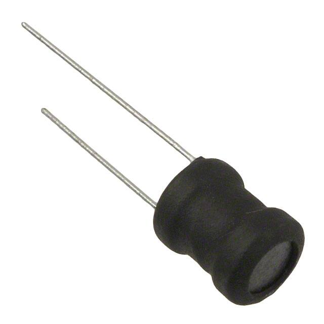
Ⅰ﹒Configuration and dimensions:
Aψ
C
F
Wψ
101
Aψ
B
White Color Marking
D
Aψ
B
C
D
F
9.30 ±0.3
11.80 ±0.3
25.00 ±5.0
18.00 ±5.0
5.00 ±0.3
Ⅱ﹒Description:
a﹒Ferrite drum core construction.
b﹒Enamelled copper wire:F class
c﹒Product weight: 1.87 g(ref.)
d﹒Moisture sensitivity Level 1
e﹒Products comply with RoHS' requirements
f﹒Halogen free available
Ⅲ﹒General specification:
a﹒Storage temp.:-40℃ 〜 +125℃
b﹒Operating temp.:-40℃ 〜 +125℃
( Temp. rise included. )
BOURNS INDUCTIVE COMPONENTS
Unit:m/m
Wψ
0.65 ±0.05
�SPECIFICATION FOR APPROVAL
PART NO.
PROD.
Radial Inductor
NAME
REF. :
RLH0912-101KBRL
REV. A ( 20121004 )
PAGE
2
Ⅳ﹒Electrical characteristics:
PART NO.
Inductance
( μH )
Q
ref.
RLH0912-101KBRL
100.0 ±10%
55
Test Freq. ( Hz )
L
Q
1K
0.796M
SRF
( MHz)
typ.
7.2
1). Electrical specifications at 25℃
2). IDC base on Temp. rise 20℃ max.
BOURNS INDUCTIVE COMPONENTS
RDC
(Ω)
max.
0.330
IDC
(A)
max.
0.66
�SPECIFICATION FOR APPROVAL
RLH0912-101KBRL
PART NO.
PROD.
Radial Inductor
NAME
REF. :
REV. A ( 20121004 )
PAGE
3
Ⅴ﹒Packaging information:
△h
H1
H2
P2
W0
W2
W1
P1 F
W3
D
P
T
Tape feed hole diameter
D
Specification
Milimeter
Size
Tolerance
Size
4.00
±0.20
0.157
Component lead pitch
F
5.00
±0.50
0.200
±0.020
△h
2.00
max.
0.079
max.
Feed hole to bottom of component
H1
18.50
±0.80
0.728
±0.040
Feed hold to overall component height
H2
30.30
±1.00
1.083
±0.040
Feed hole pitch
P
12.70
±0.30
0.500
±0.012
Lead location
P1
3.85
±0.70
0.152
±0.028
Center of component location
P2
6.35
±1.30
0.250
±0.051
Overall taped package thinkness
T
1.42
max.
0.056
max.
Feed hole location
W0
9.00
±0.50
0.354
±0.020
Adhesive tape width
W1
15.00
±0.50
0.598
±0.020
Adhesive tape position
W2
4.00
max.
0.157
max.
Tape wide
W3
18.00
±0.50
0.709
±0.020
Item
Front-to-rear deelectton
Symbol
BOURNS INDUCTIVE COMPONENTS
Inch
Tolerance
±0.008
�SPECIFICATION FOR APPROVAL
RLH0912-101KBRL
PART NO.
PROD.
Radial Inductor
NAME
REF. :
REV. A ( 20121004 )
PAGE
4
Packaging information:
1、Internal packaging: 500 Pcs / Reel
54 m/m
D
330 m/m
Cover tape
Embossed carrier
※Carrier tape width : D
350 m/m
LABEL
345 m/m
55 m/m
2、Middle packaging : 1 R / Box
375 m/m
370 m/m
375 m/m
3、External packaging: 6 Box / Carton
Q'TY & G.W.Per Packaging
Inner : Reel
PART NO.
RLH0912
Outer : Carton
Q'TY(pcs)
G.W.(gw)
Style (m/m)
Q'TY(pcs)
G.W.(Kg)
500
1100
13-54
3,000
7.20
Size (cm)
37.5x37.0x37.5
BOURNS INDUCTIVE COMPONENTS
�SPECIFICATION FOR APPROVAL
PART NO.
PROD.
Radial Inductor
NAME
REF. :
RLH0912-101KBRL
REV. A ( 20121004 )
PAGE
5
Ⅵ﹒ Reliability test:
Item
Reference documents
1.High Temperature
Exposure
MIL-STD-202 Method 108
Test Condition
1.Temperature: 125℃
2.Time:96 hours.
1.Temperature: -40℃ ~ 125℃
2.Temperature Cycling JESD22 Method JA-104
2.Number of cycle:96 cycle
3.Dwell time:30 minutes
3.Biased Humidity Test MIL-STD-202 Method 103
1.Temperature: 85±5 ℃
2.Time:96 Hours
3.Humidity: 85±5% RH.
1.Temperature: 125℃
2.Time:96 hours.
3.Apply rated current.
4.Operational Life
MIL-PRF-27
5.Exeternal Visual
MIL-STD-883 Method 2009 constructions, marking and
Inspect product
workmanship.
Test Specification
1.No mechanical and electrical
damage.
2.Inductance shall not change
more than ±10%.
1.No mechanical and electrical
damage.
2.Inductance shall not change
more than ±10%.
1.No mechanical and electrical
damage.
2.Inductance shall not change
more than ±10%.
1.No mechanical and electrical
damage.
2.Inductance shall not change
more than ±10%.
1.No pollution on the surface of
products.
2.Clear marking.
3.No crack.
6.Physical Dimensions JESD22 Method JB-100
Verify physical dimensions to
the applicable product detail
specification.
Per product specification
standard
7.Resistance to solvents MIL-STD-202 Method 215
Immerse into solvent for 3±0.5 minutes &
brush 10 times for 3 cycles.
1.No body change in apperarance.
2.No marking blurred.
3.Inductance shall not change
more than ±10%.
1.Frequency and Amplitued :
10-2000-10 Hz, 1.5 mm.
2.Direction:X, Y, Z
3.Test duration:2 hours for each direction,
6 hours in total.
1.Method:Dip
2.Temperature:260±5
3.Time(temp.≧ 260℃):10 second.
4.Number of times:3 times.
1.No mechanical and electrical
damage.
2.Inductance shall not change
more than ±10%.
8.Vibration Test
MIL-STD-202 Method 204
9.Resistance To
Soldering Heat Test
MIL-STD-202 Method 210
10.Rated current
MIL-STD-202 Method 330
11.Temperature rise
MIL-PRF-27
12.Over load
MIL-PRF-27
13.Solderability Test
J-STD-002
Dip pads in flux then dip in solder pot
at 240±5 for 5 senconds.
Teminals area must have 95% min.
Solder coverage.
14.Electrical
Characteriazation
User Spec.
1.Operating temperature: -40℃~125℃
2.Room temperature:25℃.
1.No mechanical and electrical
damage.
2.Inductance shall not change
more than ±10%.
15.Withstanding
Voltage Test
MIL-STD-202 Method 201
1.DC:500V
2.Time:1minutes
16.Drop
JESD22-B111
Packaged & Drop down from 1m.In 1 angle
1ridges & 2 surfaces orientation.
17.Terminal Strength
Test
JIS-C-6429
1.Apply push force to samples
mounted on PCB.
2.Force of 1.8 kg for 60±1 seconds.
1.No mechanical and electrical
damage.
2.Inductance shall not change
more than ±10%.
1.No mechanical and electrical
damage.
Apply rated current for 5 second.
2.Inductance shall not change
more than ±10%.
1.No mechanical and electrical
damage.
Apply rated current for 10 minutes.
2.Inductance shall not change
more than ±10%.
1.No mechanical and electrical
damage.
Apply double as rated current for 5 minutes.
(It's not application to some special design) 2.Inductance shall not change
more than ±10%.
1.During the test no breakdown.
2.The characteristic is normal after test.
1.No case deformation or change in
appearance.
2.Inductance shall not change
more than ±10%.
After test, inductors shall be no
mechanical damage.
BOURNS INDUCTIVE COMPONENTS
�
很抱歉,暂时无法提供与“RLH0912-101KBRL”相匹配的价格&库存,您可以联系我们找货
免费人工找货