Features
SA
Applications
™
n Formerly a product
n Miniature Thermal Cutoff (TCO) device
n Surface mount
n Overtemperature and overcurrent protection
00 X 2 4
6L
77
SB
0
Battery cell protection for:
n Notebook PCs
n Tablet PCs
n Smartphones
n USB cable protection for smart phones
for lithium polymer and prismatic cells
n Controls abnormal, excessive current
virtually instantaneously, up to rated limits
n Wide range of temperature options
SA Series Breaker (Surface Mount Thermal Cutoff Device)
Ratings
Specification
Trip Temperature
SA72SB0
SA77SB0
SA82SB0
SA85SB0
72 °C ± 5 °C
77 °C ± 5 °C
82 °C ± 5 °C
85 °C ± 5 °C
Reset Temperature
40 °C min.
Contact Rating
DC9 V / 25 A, 6000 cycles
Maximum Breaking Current
DC5 V / 60 A, 100 cycles
Maximum Voltage
DC28 V / 25 A, 100 cycles
Minimum Holding Voltage
3 V @ 25 °C for 1 minute
Maximum Leakage Current
200 mA max. @ 25 °C
Resistance
7 milliohms max.
Mini-breaker TCOs reset when the following conditions are met:
• T
he ambient temperature has dropped by 10 °C below the minimum trip temperature
• P
ower to the TCO has been cycled (off/on)
Agency Recognition
UL, cUL
TÜV
Description
File Number: E215638
(UL 60730)
File Number: E50373669
(EN60730-2-9)
Additional Information
How to Order
SA 77 S B 0
Series Designator
Trip Temperature (±5 °C)
• 72
• 77
• 82
• 85
Click these links for more information:
PRODUCT
TECHNICAL INVENTORY
LIBRARY
SAMPLES
CONTACT
Arm Material
S = Cu Alloy High Current Type
Terminal Type
B = 4 Terminals
(Terminal Length 1.3 mm)
Special Specification Code
Resin Type, Mfg. Internal Code, Design
Mark, etc.
WARNING Cancer and Reproductive Harm - www.P65Warnings.ca.gov
* RoHS Directive 2015/863, Mar 31, 2015 and Annex.
** Bourns considers a product to be “halogen free” if (a) the Bromine (Br) content is 900 ppm or less; (b) the Chlorine (Cl) content is 900 ppm or less; and (c) the total Bromine (Br)
and Chlorine (Cl) content is 1500 ppm or less.
Specifications are subject to change without notice.
Users should verify actual device performance in their specific applications.
The products described herein and this document are subject to specific legal disclaimers as set forth on the last page of this document, and at www.bourns.com/docs/legal/disclaimer.pdf.
�
SA Series Breaker (Surface Mount Thermal Cutoff Device)
Product Dimensions
8.0
(.315)
1.3
(.051)
5.4 +0.25/-0.05
(.213 +.010/-.002)
0.15
(.006)
1.3
(.051)
3.2 +0.15/-0.05
(.126 +.006/-.002)
0.2
R
(.008)
4 PLCS.
1.17
(.046)
1.09
(.043)
DIMENSIONS:
MM
(INCHES)
0.48
(.019)
0.08 +0.10/-0.08
(.003 +.004/-.003)
Product Structure
CASE
1.0 ± 0.05
(.039 ± .002)
2.0 ± 0.05
(.079 ± .002)
0.1 ± 0.01
(.004 ± .0004)
Circuit Diagram
ARM
COVER
PLATE
NORMAL CIRCUIT
CIRCUIT
AFTER OPENING
BASE
TERMINAL
ARM
TERMINAL
PTC
BIMETAL
DISC
CONTACT
Specifications are subject to change without notice.
Users should verify actual device performance in their specific applications.
The products described herein and this document are subject to specific legal disclaimers as set forth on the last page of this document, and at www.bourns.com/docs/legal/disclaimer.pdf.
�SA Series Breaker (Surface Mount Thermal Cutoff Device)
Typical Performance
Current vs. Temperature Curves
20
18
C (Low 67 °C avg.)
C (Low 72 °C avg.)
C (Low 77 °C avg.)
70
Current (A)
C (Low 80 °C avg.)
80
16
14
12
10
8
SA72S (Low 67 °C avg.)
6
4
2
0
SA77S (Low 72 °C avg.)
SA82S (Low 77 °C avg.)
SA85S (Low 80 °C avg.)
20
30
40
50
60
70
80
Temperature (°C)
The above curves were derived from placing non-PCB mounted test samples in an oven at 25 ℃, 40 ℃, 60 ℃, and 70 ℃, increasing current
flow through the sample at a rate of 0.1 A/minute and recording the current value when the sample trips. The current carrying performance is
influenced by the PCB design due to copper resistance; users should verify actual device performance in their specific applications.
Specifications are subject to change without notice.
Users should verify actual device performance in their specific applications.
The products described herein and this document are subject to specific legal disclaimers as set forth on the last page of this document, and at www.bourns.com/docs/legal/disclaimer.pdf.
�
SA Series Breaker (Surface Mount Thermal Cutoff Device)
Surface Mount Recommendations
Reflow Soldering:
The recommended reflow soldering
conditions are as follows:
150 ~ 180 °C................ 100 ~ 150 seconds
≤220 °C........................ 20 ~ 40 seconds
255 ~ 260 °C................ 5 ~ 10 seconds
Process breaker in a reflow furnace using
the profile shown above three times,
followed by positioning the breaker in
ambient temperature of +25 °C for 8 hours.
Temperature (°C)
The Model SA Series breaker is designed for reflow and hand soldering. It is not designed or warranted for flow soldering. The following
conditions must be adhered to:
Hand Soldering:
Place a solder iron on each of the terminal
ends for 5 seconds at +350 °C, followed by
positioning the breaker in ambient
temperature of +25 °C for 8 hours.
270
240
210
180
150
120
90
60
30
0
Recommended Reflow Profile
TEMPERATURE
_ TIME
150 ~ 180 °C ..... 100 ~ 150 Seconds
≤220 °C ..... 20 ~ 40 Seconds
245 °C ..... Peak
0
60
120
180
240
300
360
Time (Seconds)
Do not expose the breaker to temperatures exceeding +260 °C.
Recommended Land Pattern
0.6
(.024)
0.9
(.035)
9.0
(.354)
1.6
(.063)
5.8
(.228)
1.6
(.063)
Recommended Mask Thickness: 0.12 mm
2.4
(.094)
Recommended Solder Particle Size: 30 µm
0.9
(.035)
DIMENSIONS:
MM
(INCHES)
Mounting Cautions
In order to protect the housing and mechanical parts inside from deformation, prevent excessive load at the time of part absorption / part
deployment and mounting. A part absorption nozzle more than 2 mm in diameter with a 3 N (5 N max.) mounting load is recommended. Any
shock to the product by the nozzle during the mounting procedure may have a negative influence on the function of the breaker.
Specifications are subject to change without notice.
Users should verify actual device performance in their specific applications.
The products described herein and this document are subject to specific legal disclaimers as set forth on the last page of this document, and at www.bourns.com/docs/legal/disclaimer.pdf.
�SA Series Breaker (Surface Mount Thermal Cutoff Device)
Standard Packaging Specifications
Reel (13 inch)...................................................................................................................................................................5,000 pcs. (fixed)
Outer Box (690 mm x 344 mm x 136 mm).....................................................................................................................50,000 pcs. (fixed)
Marking...........................................A label will be attached on the reel and outer box which includes the following items, at a minimum:
Part name, part number, quantity, lot number, safety approval mark (UL, etc.),
company name (Bourns KK) and any other items required by the customer
2.0
(.079)
10.0
DIA.
(.394)
REEL
2.8
(.110)
2.0
(.079)
90.0
DIA.
(3.543)
330.0 ± 2.0
(12.992 ± .079)
DIA.
80.0 ± 1.0
(3.150 ± .039)
DIA.
0.2
0.4
0.6
0.8
13.0 ± 0.2
(.512 ± .008)
5.0
R
(.197)
13.0 ± 0.2
DIA.
(.512 ± .008)
2.0 ± 0.5
(.079 ± .020)
21.0 ± 0.8
DIA.
(.827 ± .031)
35 °
CENTER HOLE
ENLARGEMENT
1.0
R
(.039)
17.5 ± 1.0
(.689 ± .039)
21.5 ± 1.0
(.846 ± .039)
CARRIER TAPE
2.00 ± 0.1
(.079 ± .004)
8.00 ± 0.1
(.315 ± .004)
4.00 ± 0.1
(.157 ± .004)
DIA.
1.50 +0.1/-0
(.059 +.004/-.000)
1.75 ± 0.1
(.069 ± .004)
7.50 ± 0.1
(.295 ± .004)
5.65
(.222)
5°
16.00 +0.3/-0.1
(.630 +.012/-.004)
5°
3.75 ± 0.1
(.148 ± .004)
8.45 ± 0.1
(.333 ± .004)
1.30 ± 0.1
(.051 ± .004)
NOTES:
1) The corner and ridge radiuses (R) of inside cavity
are 0.3 mm / (.012 in.) max.
2) Cumulative tolerance of 10 pitches of the sprocket
hole is ±0.2 mm / (.008 in.).
3) Measuring of cavity positioning is based on cavity
center in accordance with JIS/IEC standard.
0.30 ± 0.05
(.012 ± .002)
1.50
(.059)
DIMENSIONS:
MM
(INCHES)
Specifications are subject to change without notice.
Users should verify actual device performance in their specific applications.
The products described herein and this document are subject to specific legal disclaimers as set forth on the last page of this document, and at www.bourns.com/docs/legal/disclaimer.pdf.
�
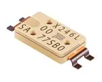
SA Series Breaker (Surface Mount Thermal Cutoff Device)
Typical Part Marking
9016L
DATE CODE:
MONTH (1~9, X, Y, Z)
DATE
YEAR
MACHINE NO.
ROMAN NUMERAL (I, II, III, ETC.) or
ARABIC NUMERAL (1, 2, 3, ETC.) = OKAYAMA FACTORY
ALPHABET = SHIGA FACTORY
11
SA
77SB0
SPECIAL SPECIFICATION CODE
(RESIN TYPE, MFG. INTERNAL CODE,
DESIGN MARK, ETC.)
SERIES DESIGNATOR
MANUFACTURER’S
INTERNAL CODE
(ALPHANUMERIC CHARACTER)
TERMINAL TYPE
ARM MATERIAL
(S = Cu ALLOY HIGH CURRENT TYPE)
TRIP TEMPERATURE - °C
(72, 77, 82, 85)
Application Temperature Range
........................................... -30 ~ 100 °C
Storage Conditions
1) .The breaker must be stored in the standard packaging with the following conditions:
ambient temperature of -10 to +40 °C, RH