CO
LO & MP
LI
GE
AN
N
T
FR
EE
SinglFuse™ SF-3812TM-T Series Features
■ Replacement for Bourns® Telefuse™
*R
oH
S
■ UL 248-14 compliant
■ For use in telecommunication circuit
■ Surface mount packaging
applications requiring low current
protection with high surge tolerance
5
0.
**
HA
■ EIA 3812 (10030 metric) footprint
models B0500T, B1250T and B2000T
for automated assembly
■ RoHS compliant* and halogen free**
■ Overcurrent protection to Telcordia
GR-1089-CORE Issue 7 & UL 60950
SF-3812TM-T Series – SinglFuse™ Telefuse™ Telecom Protectors
Clearing Time Characteristics for Series
Additional Information
Click these links for more information:
Clearing Time at 25 °C
% of Current Rating
Min.
Max.
100 %
4 hours
—
250 %
1 second
120 seconds
PRODUCT TECHNICAL INVENTORY SAMPLES
SELECTOR LIBRARY
CONTACT
Electrical Characteristics
Rated
Current (A)
Resistance
(Ω) Typ.***
SF-3812TM050T-2
0.50
0.48
SF-3812TM125T-2
1.25
0.1
SF-3812TM200T-2
2.00
0.055
Model
Rated
Voltage
Interrupting
Rating
Typical
I t (A2s) ****
Max. Power
Dissipation
(W)
cUL: E198545
1.4
0.4
✓
22
0.6
✓
24
0.8
✓
2
60 A @ 600 VAC
60 A @ 250 VAC
600 VAC
50 A @ 250 VDC
100 A @ 125 VDC
Certifications
*** Resistance value measured with ≤10 % rated current at 25 °C ambient. Tolerance ± 30 %.
**** Melting I2t calculated at 10 times rated current.
Environmental Characteristics
Operating Temperature................................................................................................................................................................ -55 °C to +125 °C
Storage Conditions
Temperature ............................................................................................................................................................................ +15 °C to +30 °C
Humidity......................................................................................................................................................................................... 20 % to 70 %
Shelf Life..........................................................................................................................................................2 years from manufacturing date
Moisture Sensitivity Level ...................................................................................................................................................................................... 1
ESD Classification (HBM)............................................................................................................................................................................ Class 6
WARNING Cancer and Reproductive Harm - www.P65Warnings.ca.gov
* RoHS Directive 2015/863, Mar 31, 2015 and Annex.
** Bourns considers a product to be “halogen free” if (a) the Bromine (Br) content is 900 ppm or less; (b) the Chlorine (Cl) content is 900 ppm or less; and (c) the total Bromine (Br) and
Chlorine (Cl) content is 1500 ppm or less.
“SinglFuse” is a trademark of Bourns, Inc.
Specifications are subject to change without notice.
The device characteristics and parameters in this data sheet can and do vary in different applications and actual device performance may vary over time.
Users should verify actual device performance in their specific applications.
�SF-3812TM-T Series – SinglFuse™ Telefuse™ Telecom Protectors
Average I2t vs. t Curves
Average Pre-Arcing Time vs. Current Curves
1.25 A
0.50 A
2.00 A
100000
10000
2.00 A
1.25 A
10000
100
0.50 A
1000
10
I2t (A2s)
PRE-ARCING TIME (SECONDS)
1000
1
0.1
100
10
0.01
1
0.001
0.0001
0.1
1
10
CURRENT (A)
100
0.1
0.001
0.01
0.1
1
10
100
1000
10000
TIME (SECONDS)
Specifications are subject to change without notice.
Users should verify actual device performance in their specific applications.
The products described herein and this document are subject to specific legal disclaimers as set forth on the last page of this document, and at www.bourns.com/docs/legal/disclaimer.pdf.
�SF-3812TM-T Series – SinglFuse™ Telefuse™ Telecom Protectors
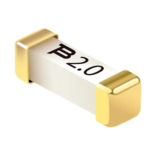
Typical Part Marking
How to Order
Represents total content. Layout may vary.
0.5
Rated Current
Part Marking
0.5 A
0.5
1.25 A
1.25
2.0 A
2.0
Packaging
SF - 3812 TM 050 T - 2
Reel Dimension
13-inch Tape and Reel
SinglFuse™
Product Designator
Specification
EIA 481-2
SMD Footprint
3812 = EIA 3812
(10030 metric)
Quantity
2,500 pieces
Packaging Code
-2
Fuse Blow Type
TM = Time Lag, Telecom
Recommended Pad Layout
Rated Current
050 ~ 200 (0.50 A ~ 2.00 A)
6.10
(.240)
Structure Type
T = Ceramic Tube
Packaging Type
- 2 = Tape & Reel
3.43
(.135)
Product Dimensions
3.25
(.128)
3.10 ± 0.20
(.122 ± .008)
10.10 ± 0.40
(.398 ± .016)
DIMENSIONS:
MM
(INCHES)
0.5
2.65 ± 0.20
(.104 ± .008)
1.75 ± 0.20
(.069 ± .008)
3.10 ± 0.20
(.122 ± .008)
DIMENSIONS:
MM
(INCHES)
RATED CURRENT PERCENTAGE (%)
Current Rating Thermal Derating Curve
120
100
80
60
40
25 °C
20
0
-60
-40
-20
0
20
40
60
80
100
120
140
AMBIENT TEMPERATURE (°C)
Specifications are subject to change without notice.
Users should verify actual device performance in their specific applications.
The products described herein and this document are subject to specific legal disclaimers as set forth on the last page of this document, and at www.bourns.com/docs/legal/disclaimer.pdf.
�SF-3812TM-T Series – SinglFuse™ Telefuse™ Telecom Protectors
Solder Reflow Recommendations
tp
TP
Profile Feature
CRITICAL ZONE
T L TO TP
RAMP-UP
Temperature
TL
tL
TS MAX.
RAMP-DOWN
TS MIN.
ts
PREHEAT
25 °C
t 25 °C TO PEAK
Time
Preheat / Soak:
Temperature Min. (Tsmin)
Temperature Max. (Tsmax)
Time (ts) from (Tsmin to Tsmax)
Pb-Free Assembly
150 °C
200 °C
60~180 seconds
Ramp Up Rate (TL to Tp)
3 °C / second max.
Ramp Up Rate (Tsmax to TL)
5 °C / second max.
Liquidous Temperature (TL)
Time (tL) maintained above TL
217 °C
60~90 seconds
Peak Package Body
Temperature (Tp)
260 °C +0/-5 °C
Time within 5 °C of actual peak
temperature (Tp)
10~30 seconds*
Ramp Down Rate (Tp to TL)
6 °C / second max.
Time 25 °C to Peak Temperature
8 minutes max.
Do not exceed
260 °C
* Tolerance for peak profile temperature (Tp ) is defined as a
supplier minimum and a user maximum.
Solder Wave Recommendations
Peak Temperature (Dwell Time)
300
Profile Feature
280
260
Preheat:
Temperature Max. (Tsmax)
Time (Min. to Max.)
240
Temperature (°C)
220
200
180
160
140
Pb-Free Assembly
150 °C
60~90 seconds
Solder Pot Temperature
260 °C max.
Solder Dwell Time
2~3 seconds
120
100
80
60
40
20
0
20
40
60
PREHEAT TIME
80
100
120
140
160
180
200
220
240
COOLING TIME
Time (Sec.)
Specifications are subject to change without notice.
Users should verify actual device performance in their specific applications.
The products described herein and this document are subject to specific legal disclaimers as set forth on the last page of this document, and at www.bourns.com/docs/legal/disclaimer.pdf.
�SF-3812TM-T Series – SinglFuse™ Telefuse™ Telecom Protectors
Lightning Surge Specifications (Fuse Not Allowed to Open)
Surge Specification
Max. Rise / Min.
Decay (μ sec.)
Min. Peak Current
(A)
Min. Peak Voltage
(V)
Repetitions Each
Polarity
Recommended
Fuse
100
600
25
1.25 A / 2 A
100
1000
25
1.25 A / 2 A
100*
2000
5
1.25 A / 2 A
160
4000
5
1.25 A / 2 A
100
1000
25
1.25 A / 2 A
25
1000
5
0.5 A / 1.25 A / 2 A
200*
4000
5
1.25 A / 2 A
750*
6000
1
1.25 A / 2 A
600*
6000
5
1.25 A / 2 A
300
5000
5
1.25 A / 2 A
800*
2000
5
1.25 A / 2 A
750
1500
5
1.25 A / 2 A
400
800
5
1.25 A / 2 A
300
600
5
1.25 A / 2 A
500
5000
1
1.25 A / 2 A
500
2500
10
1.25 A / 2 A
300
1500
10
1.25 A / 2 A
200
1000
5
1.25 A / 2 A
100
800
5
1.25 A / 2 A
10 / 1000
10 / 700
10 / 360
10 / 250
Telcordia GR-1089
8 / 20
2 / 10
* Additional impedance devices utilized for the test.
Surge
Specification
FCC Part 68
(TIA-968-A)
Surge
Specification
Surge
Waveform
(μ sec.)
Current
(A)
Voltage
(V)
Repetitions
(Each)
Recommended
Fuse
Metallic A
10 x 560
100
800
1
1.25 A / 2 A
Longitudinal A
10 x 160
200
1500
1
1.25 A / 2 A
Surge
Waveform
(μ sec.)
Current
(A)
Voltage
(V)
Repetitions
(Each)
Recommended
Fuse
37.5
1500
5
0.5 A / 1.25 A / 2 A
62.5
2500
5
0.5 A / 1.25 A / 2 A
Non-handheld
UL / EN 60950
(ITU-T K20)
10 x 700
Handheld Units
Specifications are subject to change without notice.
Users should verify actual device performance in their specific applications.
The products described herein and this document are subject to specific legal disclaimers as set forth on the last page of this document, and at www.bourns.com/docs/legal/disclaimer.pdf.
�SF-3812TM-T Series – SinglFuse™ Telefuse™ Telecom Protectors
AC Power Fault Tests (Fuse Not Allowed to Open)
GR-1089
1st Level Test
Voltage
(Vrms)
Short Circuit
Current (A)
Hits
Duration
Recommended Fuse
1
50
0.33
1
15 min.
0.5 A / 1.25 A / 2 A
2
100
0.17
1
15 min.
0.5 A / 1.25 A / 2 A
3
600
0.5
1
30 sec.
0.5 A / 1.25 A / 2 A
4
1000
1
60
1 sec.
0.5 A / 1.25 A / 2 A
5
200
0.47
60
1 sec.
0.5 A / 1.25 A / 2 A
6
425
0.71
5
2 sec.
0.5 A / 1.25 A / 2 A
7
440
2.2
5
2 sec.
1.25 A / 2 A
8
600
3
1
1.1 sec.
1.25 A / 2 A
9
1000
5
1
0.4 sec.
1.25 A / 2 A
Note: These tests can be performed at a higher voltage, but the current must be as specified.
AC Current Limiting Protector Tests / Fusing Coordination Tests
Maximum Time For Fuse to Open (seconds)
Voltage (VAC)
600
Current (A)
Duration
0.50 A
1.25 A
2.00 A
2.20
1.0
will not open
will not open
2.60
0.8
900
will not open
3.00
0.5
20
will not open
3.75
0.3
10
20
5.00
0.2
4
10
0.1
2
4
10.00
0.05
1
1.2
12.50
0.03
0.40
0.6
20.00
0.01
0.14
0.2
25.00
0.008
0.08
0.14
30.00
0.006
0.04
0.10
7.00
up to 15 min.
Specifications are subject to change without notice.
Users should verify actual device performance in their specific applications.
The products described herein and this document are subject to specific legal disclaimers as set forth on the last page of this document, and at www.bourns.com/docs/legal/disclaimer.pdf.
�SF-3812TM-T Series – SinglFuse™ Telefuse™ Telecom Protectors
Reliability Testing
No.
Test
Test Condition
Requirement
Test Reference
1
Solderability
Temperature setup: 235 ±5 °C
Time setup: 10 ±1 sec.
After test terminal electrode wetting
area must be greater than 95 %
IEC 60068-2-58
2
Resistance to
soldering heat
Temperature setup: 260 +0/-5 °C
Time setup: 10 sec. max.
DCR change ≤ ±15 %
IEC 60068-2-58
3
Thermal shock
Temperature setup:
25 °C ~ -65 °C ~ 25 °C ~ 125 °C
Time setup: -65 °C (30 min)
~ 25 °C (5 min) ~ 125 °C (30 min)
~ 25 °C (5 min), 5 cycles
DCR change ≤ ±15 %
No mechanical damage
MIL-STD-202G
Method 107G
Test Condition B
4
Humidity unload
Heat (85 ±0.5 °C)
High Humidity (85 ±1 % RH)
240 hours
DCR change ≤ ±15 %
No mechanical damage
MIL-STD-202G
Method 103B
Test Condition A
5
Salt spray
Salt spray concentration: 5 ±1 %
Test liquid temperature: 35 ±0.5 °C
96 hours
DCR change ≤ ±15 %
No mechanical damage
MIL-STD-202G
Method 101E
Test Condition A
6
Bending
The board shall be bent by 1 mm
at a rate of 1 mm/sec.
DCR change ≤ ±15 %
IEC 60127-4
7
Vibration
Frequency setup: 10 ~ 55 ~ 10 Hz
Time setup: 1 Minute/cycle
(X-Y-Z, 120 cycles, 6 hours)
DCR change ≤ ±15 %
No mechanical damage
MIL-STD-202G
Method 201A
Asia-Pacific: Tel: +886-2 2562-4117 • Email: asiacus@bourns.com
EMEA: Tel: +36 88 885 877 • Email: eurocus@bourns.com
The Americas: Tel: +1-951 781-5500 • Email: americus@bourns.com
www.bourns.com
REV. 04/21
Specifications are subject to change without notice.
Users should verify actual device performance in their specific applications.
The products described herein and this document are subject to specific legal disclaimers as set forth on the last page of this document, and at www.bourns.com/docs/legal/disclaimer.pdf.
�Legal Disclaimer Notice
This legal disclaimer applies to purchasers and users of Bourns® products manufactured by or on behalf of Bourns, Inc. and
P[Z�HɉSPH[LZ��JVSSLJ[P]LS`��¸)V\YUZ¹��
Unless otherwise expressly indicated in writing, Bourns® products and data sheets relating thereto are subject to change
^P[OV\[�UV[PJL���
很抱歉,暂时无法提供与“SF-3812TM200T-2”相匹配的价格&库存,您可以联系我们找货
免费人工找货- 国内价格
- 1+9.93600
- 10+9.70920
- 30+9.55800