Features
Applications
■ RoHS compliant*
■ IEC 61000-4-2 ESD (Min. Level 4)
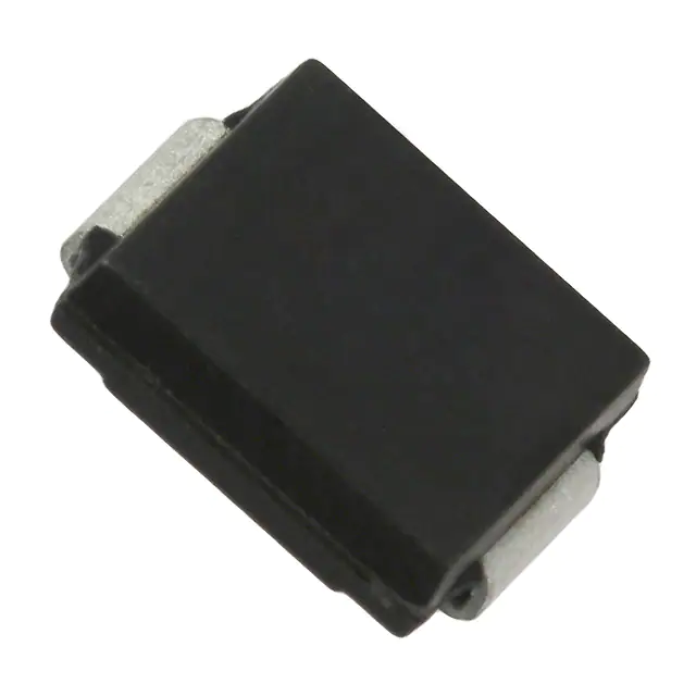
■ Surface Mount SMC package
■ IEC 61000-4-4 EFT
■ Standoff Voltage: 5.0 to 170 volts
■ IEC 61000-4-5 Surge
■ Power Dissipation: 3000 watts
■ Typical temperature coefficient:
ΔVBR = 0.1 % x VBR @ 25 °C x ΔT
SMLJ Transient Voltage Suppressor Diode Series
General Information
Additional Information
The markets of portable communications, computing and video equipment are challenging
the semiconductor industry to develop increasingly smaller electronic components.
Click these links for more information:
Bourns offers Transient Voltage Suppressor Diodes for surge and ESD protection
applications, in compact chip package DO-214AB (SMC) size format. The Transient Voltage
Suppressor series offers a choice of Working Peak Reverse Voltage from 5 V up to 170 V
and Breakdown Voltage up to 200 V. Typical fast response times are less than 1.0 ps for
unidirectional devices and less than 5.0 ps for bidirectional devices from 0 V to Minimum
Breakdown Voltage.
PRODUCT TECHNICAL INVENTORY SAMPLES
SELECTOR LIBRARY
CONTACT
Agency Recognition
Description
Bourns® Chip Diodes conform to JEDEC standards, are easy to handle with standard pick
and place equipment and the flat configuration minimizes roll away.
UL
File Number: E153537
Electrical Characteristics (@ TA = 25 °C Unless Otherwise Noted)
Parameter
Symbol
Value
Unit
Minimum Peak Pulse Power Dissipation (TP = 1 ms) (Note 1,2)
PPK
3000
Watts
Peak Forward Surge Current
8.3 ms Single Half Sine Wave Superimposed on Rated Load
(JEDEC Method) (Note 3)
IFSM
300
Amps
PM(AV)
5.0
Watts
VF
3.5
5.0
Volts
TJ
-55 to +150
°C
TSTG
-55 to +150
°C
Steady State Power Dissipation @ TL = 75 °C
Maximum Instantaneous Forward Voltage @ IPP = 100 A
(For Unidirectional Units Only)
SMLJ5.0A ~ SMLJ90A
SMLJ100A ~ SMLJ170A
Operating Temperature Range
Storage Temperature Range
1.
2.
3.
Non-repetitive current pulse, per Pulse Waveform graph and derated above TA = 25 °C per Pulse Derating Curve.
Thermal Resistance Junction to Lead.
8.3 ms Single Sine Wave duty cycle = 4 pulses maximum per minute (unidirectional units only).
How to Order
SMLJ 5.0 CA - H
Package
SMLJ = SMC/DO-214AB
Working Peak Reverse Voltage
5.0 = 5.0 VRWM (Volts)
Asia-Pacific: Tel: +886-2 2562-4117 • Email: asiacus@bourns.com
EMEA: Tel: +36 88 885 877 • Email: eurocus@bourns.com
The Americas: Tel: +1-951 781-5500 • Email: americus@bourns.com
www.bourns.com
Suffix
A = 5 % Tolerance Unidirectional Device
CA = 5 % Tolerance Bidirectional Device
Reel
(blank) = 13 inch reel
-H = 7 inch reel
WARNING Cancer and Reproductive Harm - www.P65Warnings.ca.gov
*RoHS Directive 2015/863, Mar 31, 2015 and Annex.
Specifications are subject to change without notice.
Users should verify actual device performance in their specific applications.
The products described herein and this document are subject to specific legal disclaimers as set forth on the last page of this document, and at www.bourns.com/docs/legal/disclaimer.pdf.
�SMLJ Transient Voltage Suppressor Diode Series
Electrical Characteristics (@ TA = 25 °C Unless Otherwise Noted)
Unidirectional
Device
Part
Number
Part
Marking
Bidirectional Device
Part
Number
Part
Marking
Breakdown
Voltage
VBR (Volts)
Min.
@ IT
Max.
(mA)
Working Maximum Maximum
Peak
Reverse Clamping
Voltage
Reverse Leakage
@ Ipp
Voltage @ VRWM
VRWM
(V)
SMLJ5.0A
HDE
SMLJ5.0CA
IDE
6.40
7.00
10
5
SMLJ6.0A
HDG
SMLJ6.0CA
IDG
6.67
7.37
10
6
SMLJ6.5A
HDK
SMLJ6.5CA
IDK
7.22
7.98
10
6.5
SMLJ7.0A
HDM
SMLJ7.0CA
IDM
7.78
8.60
10
7
SMLJ7.5A
HDP
SMLJ7.5CA
IDP
8.33
9.21
1
7.5
SMLJ8.0A
HDR
SMLJ8.0CA
IDR
8.89
9.83
1
8
SMLJ8.5A
HDT
SMLJ8.5CA
IDT
9.44
10.4
1
8.5
SMLJ9.0A
HDV
SMLJ9.0CA
IDV
10.0
11.1
1
9
SMLJ10A
HDX
SMLJ10CA
IDX
11.1
12.3
1
10
SMLJ11A
HDZ
SMLJ11CA
IDZ
12.2
13.5
1
11
SMLJ12A
HEE
SMLJ12CA
IEE
13.3
14.7
1
12
SMLJ13A
HEG
SMLJ13CA
IEG
14.4
15.9
1
13
SMLJ14A
HEK
SMLJ14CA
IEK
15.6
17.2
1
14
SMLJ15A
HEM
SMLJ15CA
IEM
16.7
18.5
1
15
SMLJ16A
HEP
SMLJ16CA
IEP
17.8
19.7
1
16
SMLJ17A
HER
SMLJ17CA
IER
18.9
20.9
1
17
SMLJ18A
HET
SMLJ18CA
IET
20.0
22.1
1
18
SMLJ20A
HEV
SMLJ20CA
IEV
22.2
24.5
1
20
SMLJ22A
HEX
SMLJ22CA
IEX
24.4
26.9
1
22
SMLJ24A
HEZ
SMLJ24CA
IEZ
26.7
29.5
1
24
SMLJ26A
HFE
SMLJ26CA
IFE
28.9
31.9
1
26
SMLJ28A
HFG
SMLJ28CA
IFG
31.1
34.4
1
28
SMLJ30A
HFK
SMLJ30CA
IFK
33.3
36.8
1
30
SMLJ33A
HFM
SMLJ33CA
IFM
36.7
40.6
1
33
SMLJ36A
HFP
SMLJ36CA
IFP
40
44.2
1
36
SMLJ40A
HFR
SMLJ40CA
IFR
44.4
49.1
1
40
SMLJ43A
HFT
SMLJ43CA
IFT
47.8
52.8
1
43
SMLJ45A
HFV
SMLJ45CA
IFV
50
55.3
1
45
SMLJ48A
HFX
SMLJ48CA
IFX
53.3
58.9
1
48
SMLJ51A
HFZ
SMLJ51CA
IFZ
56.7
62.7
1
51
SMLJ54A
HGE
SMLJ54CA
IGE
60
66.3
1
54
SMLJ58A
HGG
SMLJ58CA
IGG
64.4
71.2
1
58
SMLJ60A
HGK
SMLJ60CA
IGK
66.7
73.7
1
60
SMLJ64A
HGM
SMLJ64CA
IGM
71.1
78.6
1
64
SMLJ70A
HGP
SMLJ70CA
IGP
77.8
86.0
1
70
SMLJ75A
HGR
SMLJ75CA
IGR
83.3
92.1
1
75
SMLJ78A
HGT
SMLJ78CA
IGT
86.7
95.8
1
78
SMLJ85A
HGV
SMLJ85CA
IGV
94.4
104
1
85
SMLJ90A
HGX
SMLJ90CA
IGX
100
111
1
90
SMLJ100A
HGZ
SMLJ100CA
IGZ
111
123
1
100
SMLJ110A
HHE
SMLJ110CA
IHE
122
135
1
110
SMLJ120A
HHG
SMLJ120CA
IHG
133
147
1
120
SMLJ130A
HHH
SMLJ130CA
IHH
144
159
1
130
SMLJ150A
HHM
SMLJ150CA
IHM
167
185
1
150
SMLJ160A
HHP
SMLJ160CA
IHP
178
197
1
160
SMLJ170A
HHR
SMLJ170CA
IHR
189
209
1
170
Notes:
1. Suffix ‘A’ denotes a 5 % tolerance unidirectional device.
2. Suffix ‘CA’ denotes a 5 % tolerance bidirectional device.
3. For bidirectional devices with a VR of 10 volts or less, the IR limit is double.
Maximum
Peak
Pulse
Current
Maximum
Clamping
Voltage
@ Ipp
Maximum
Peak
Pulse
Current
(10/1000 μs)
(10/1000 μs)
(8/20 μs)
(8/20 μs)
IR
(μA)
Vc
(V)
Ipp
(A)
Vc
(V)
Ipp
(A)
1000
1000
500
200
100
50
25
10
5
5
2
2
2
2
2
2
2
2
2
2
2
2
2
2
2
2
2
2
2
2
2
2
2
2
2
2
2
2
2
2
2
2
2
2
2
2
9.2
10.3
11.2
12
12.9
13.6
14.4
15.4
17
18.2
19.9
21.5
23.2
24.4
26
27.6
29.2
32.4
35.5
38.9
42.1
45.4
48.4
53.3
58.1
64.5
69.4
72.7
77.4
82.4
87.1
93.6
96.8
103
113
121
126
137
146
162
177
193
209
243
259
275
326.00
291.30
267.90
250.00
232.60
220.60
208.40
194.80
176.40
164.80
150.60
139.40
129.40
123.00
115.40
106.60
102.80
92.60
84.40
77.20
71.20
66.00
62.00
56.20
51.60
46.40
43.20
41.20
38.80
36.40
34.40
32.00
31.00
29.20
26.60
24.80
22.80
20.80
20.60
18.60
16.80
15.60
14.40
12.40
11.60
11.00
12.00
13.40
14.60
15.60
16.80
17.70
18.70
20.00
22.10
23.70
25.90
28.00
30.20
31.70
33.80
35.90
38.00
42.10
46.20
50.60
54.70
59.00
62.90
69.30
75.50
83.90
90.20
94.50
100.60
107.10
113.20
121.70
125.80
133.90
146.90
157.30
163.80
178.10
189.80
210.60
230.10
250.90
271.70
315.90
336.70
357.50
1630.50
1456.50
1339.50
1250.00
1163.00
1103.00
1041.50
974.00
882.50
824.00
754.00
697.50
646.50
615.00
577.00
543.50
513.50
463.00
422.50
385.50
356.50
330.50
310.00
281.50
258.00
232.50
216.00
206.50
194.00
182.00
172.00
160.50
155.00
145.50
132.50
124.00
119.00
109.50
102.50
92.50
84.50
77.50
72.00
61.50
58.00
54.50
Specifications are subject to change without notice.
Users should verify actual device performance in their specific applications.
The products described herein and this document are subject to specific legal disclaimers as set forth on the last page of this document, and at www.bourns.com/docs/legal/disclaimer.pdf.
�SMLJ Transient Voltage Suppressor Diode Series
Product Dimensions
Recommended Footprint
a
A
B
b
C
c
G
Dimension
a (Max.)
F
H
D
b (Min.)
E
c (Min.)
Dimension
A
B
C
D
E
F
G
H
SMC (DO-214AB)
6.60 - 7.11
(0.260 - 0.280)
5.59 - 6.22
(0.220 - 0.245)
2.90 - 3.20
(0.114 - 0.126)
0.15 - 0.31
(0.006 - 0.012)
7.75 - 8.13
(0.305 - 0.320)
0.05 - 0.20
(0.002 - 0.008)
2.00 - 2.62
(0.079 - 0.103)
0.76 - 1.52
(0.030 - 0.060)
DIMENSIONS:
SMC (DO-214AB)
4.69
(0.185)
3.07
(0.121)
1.52
(0.060)
DIMENSIONS:
MM
(INCHES)
Physical Specifications
Case ............................................ Molded plastic per UL Class 94V-0
Polarity.........................Cathode band indicates unidirectional device
No cathode band indicates bidirectional device
MM
(INCHES)
Specifications are subject to change without notice.
Users should verify actual device performance in their specific applications.
The products described herein and this document are subject to specific legal disclaimers as set forth on the last page of this document, and at www.bourns.com/docs/legal/disclaimer.pdf.
�SMLJ Transient Voltage Suppressor Diode Series
Rating & Characteristic Curves
Pulse Derating Curve
Maximum Non-Repetitive Surge Current
300
Peak Forward Surge Current (Amps)
Peak Pulse Derating in Percent of
Peak Power or Current
100
75
50
25
10 x 1000 Waveform as Defined
by R.E.A.
250
200
150
100
0
0
25
0
50
75
100
Pulse Width 8.3 ms
Single Half Sine-Wave
(JEDEC Method)
50
125
150
175
1
200
2
5
Junction Temperature (°C)
Pulse Waveform
20
50
100000
Peak value (IRSM)
Half value=
TA= 25 °C
10000
IRSM
2
CJ - Junction Capacitance (pF)
100
100
Typical Junction Capacitance
TR=10 µs
IP, Peak Pulse Current (%)
10
Number of Cycles at 60 Hz
Pulse width (TP)
is defined as that point
where the peak current
decays to 50 % of IPSM.
50
10 x 1000 waveform
as defined by R.E.A.
TA=25 °C
TP
Bidirectional
1000
Unidirectional
100
10
0
0
1.0
2.0
3.0
1
4.0
1000
Steady State Power Derating Curve
5.0
TA = 25 °C
Non-repetitive Pulse Waveform
Shown in Pulse Waveform Graph
10
1.0
8.0 mm Lead Areas
1.0 µs
10 µs
100 µs
TP, Pulse Width
1.0 ms
10 ms
RM(AV) Steady State Power Dissipation (W)
100
PP, Peak Power (KW)
100
VBR - Reverse Breakdown Voltage (V)
Pulse Rating Curve
0.1
0.1 µs
10
1
T, Time (ms)
4.0
3.0
2.0
1.0
60 Hz Resistive or
Inductive Load
0.0
0
25
50
75
100
125
150
175
200
TL, Lead Temperature (°C)
Specifications are subject to change without notice.
Users should verify actual device performance in their specific applications.
The products described herein and this document are subject to specific legal disclaimers as set forth on the last page of this document, and at www.bourns.com/docs/legal/disclaimer.pdf.
�SMLJ Transient Voltage Suppressor Diode Series
Packaging Information
The product will be dispensed in tape and reel format (see diagram below).
P
0
P
1
d
T
E
Index Hole
120 °
F
D2
W
B
D1 D
P
Trailer
.......
.......
End
A
Unidirectional
Product
Orientation
C
Device
.......
.......
.......
.......
Leader
.......
.......
10 pitches (min.)
W1
Start
DIMENSIONS:
10 pitches (min.)
Devices are packed in accordance with EIA standard
RS-481-A and specifications shown here.
Direction of Feed
Item
Symbol
7 Inch Reel
Carrier Width
A
Carrier Length
B
Carrier Depth
C
Sprocket Hole
d
Reel Outside Diameter
D
Reel Inner Diameter
D1
Feed Hole Diameter
D2
Sprocket Hole Position
E
Punch Hole Position
F
Punch Hole Pitch
P
Sprocket Hole Pitch
P0
Embossment Center
P1
Overall Tape Thickness
T
Tape Width
W
Reel Width
W1
Quantity per Reel
--
MM
(INCHES)
178
(7.008)
500
SMC (DO-214AB)
13 Inch Reel
6.0 ± 2.0
(0.236 - 0.079)
8.3 ± 0.20
(0.327 ± 0.008)
2.5 ± 0.20
(0.098 ± 0.008)
1.50 ± 0.10
(0.059 ± 0.004)
330
(12.992)
50.0
MIN.
(1.969)
13.0 +0.50/-0.20
(0.512 +0.020/-0.008)
1.75 ± 0.10
(0.069 ± 0.004)
7.50 ± 0.10
(0.295 ± 0.004)
8.00 ± 0.10
(0.315 ± 0.004)
4.00 ± 0.10
(0.157 ± 0.004)
2.00 ± 0.10
(0.079 ± 0.004)
0.30 ± 0.10
(0.012 ± 0.004)
16.00 ± 0.30
(0.630 ± 0.012)
22.4
MAX.
(0.882)
3,000
REV. 02/21
Specifications are subject to change without notice.
Users should verify actual device performance in their specific applications.
The products described herein and this document are subject to specific legal disclaimers as set forth on the last page of this document, and at www.bourns.com/docs/legal/disclaimer.pdf.
�Legal Disclaimer Notice
This legal disclaimer applies to purchasers and users of Bourns® products manufactured by or on behalf of Bourns, Inc. and
P[Z�HɉSPH[LZ��JVSSLJ[P]LS`��¸)V\YUZ¹��
Unless otherwise expressly indicated in writing, Bourns® products and data sheets relating thereto are subject to change
^P[OV\[�UV[PJL���
很抱歉,暂时无法提供与“SMLJ64CA”相匹配的价格&库存,您可以联系我们找货
免费人工找货- 国内价格 香港价格
- 3000+4.779303000+0.61833
- 6000+4.457926000+0.57675
- 9000+4.294249000+0.55558
- 15000+4.1150515000+0.53240
- 国内价格 香港价格
- 1+17.517771+2.26639
- 10+11.1324010+1.44028
- 100+7.48502100+0.96839
- 500+5.92107500+0.76605
- 1000+5.417981000+0.70096