Features
This series is currently available,
but not recommended for new
designs. The newer SRP1238A
series is recommended.
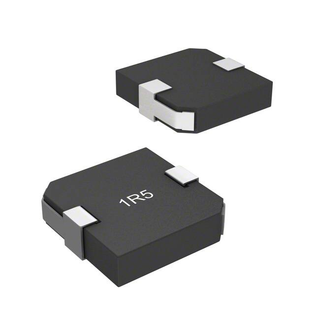
n Shielded construction
n Unit height of 3.7 mm
n Inductance range: 0.1 to 10 μH
1R0 9
172
n Current up to 43 A
n RoHS compliant*
SRP1235 Series - Shielded Power Inductors
General Specifications
Test Voltage........................................1 V
Test Frequency.......................... 100 KHz
Reflow Soldering... 230 °C; 50 sec. max.
Operating Temperature
.................................-40 °C to +125 °C
(Temperature rise included)
Storage Temperature (On Board)
.................................-40 °C to +125 °C
Resistance to Soldering Heat
.............................. +260 °C for 10 sec.
Moisture Sensitivity Level......................1
ESD Classification (HBM).................N/A
Electrical Specifications
Bourns Part No.
Inductance
L (μH) ±20 %
I rms
(A)
I sat
(A)
DCR
(mΩ) Max.
SRF
(MHz) Typ.
SRP1235-R15M
0.15
41.0
50
1.2
100
SRP1235-R10M
0.10
SRP1235-R22M
0.22
SRP1235-R33M
SRP1235-R67M
SRP1235-R68M
28.0
0.68
SRP1235-R82M
0.82
SRP1235-1R0M
1.00
SRP1235-1R2M
1.20
SRP1235-1R5M
SRP1235-1R8M
1.80
SRP1235-2R2M
2.20
SRP1235-3R3M
16.0
3.30
SRP1235-4R7M
4.70
SRP1235-5R6M
10.0
5.60
SRP1235-6R8M
6.80
SRP1235-8R2M
9.0
8.20
SRP1235-100M
18
12
14
18
20
15
12
34
11
Maximum of 10 seconds
between +255 °C and +260 °C
190°C
220 °C
60 seconds
maximum
Ramp Down
5 °C/second
150 °C
125
120-150 seconds
2.5
(.099)
75
25
260 °C peak
255 °C
0
4.5
(.177)
1.5
(.060)
Electrical Schematic
10 seconds minimum
100
at +245 °C
225
150
Time (Seconds)
200
250
300
245 °C
12.7 ± 0.3
(0.500 ± 0.012)
175
170 °C
150 °C
183 °C
60 seconds
maximum
125
120 -150 seconds
R
5
10 seconds minimum
75
Ramp Up
4 °C/second maximum
50
1R0
1729
5 seconds maximum
275
Temperature (°C)
Temperature (°C)
275
175
3.5
(.138)
MAX.
13.5
(0.531)
MAX.
Soldering Profile
225
3.7
(.146)
MAX.
13.9
MAX.
(0.547)
12.7 ± 0.3
(0.500 ± 0.012)
14
28
9.5
Product Dimensions
16
22
12
7.0
27
15
13
8.5
10.0
32
8
16
10.0
37
7
20
12.0
37
5.5
24
Materials
Core...................................................Iron
Wire.............................Enameled copper
Terminal.........................................Cu/Sn
Rated Current......Ind. drops 20 % at Isat
Temperature Rise......40 °C at rated Irms
Packaging........ 600 pcs. per 13-inch reel
60
4.5
28
16.5
65
3.5
29
19.0
72
3.0
36
21.0
1.50
72
2.5
38
24.0
73
2.5
40
25.0
85
2.5
40
28.0
90
2.0
42
105
94
1.5
44
29.0
0.67
1.3
50
32.0
0.60
0.96
50
36.5
0.47
SRP1235-R60M
56
38.5
0.33
SRP1235-R47M
43.0
25
3.0 ± 0.5 Ramp Up
(0.118 ± 0.020)4 °C/second maximum
0
50
100
200
2.5 ± 0.5 150
(0.098 ±Time
0.020) (Seconds)
Recommended Layout
4.5
(.177)
15.0
(0.591)
7.0
(.276)
MM
WARNING Cancer and Reproductive Harm - www.P65Warnings.ca.gov
DIMENSIONS:
(INCHES)
*RoHS Directive 2015/863, Mar 31, 2015 and Annex.
Specifications are subject to change without notice.
Users should verify actual device performance in their specific applications.
The products described herein and this document are subject to specific legal disclaimers as set forth on the last page of this document, and at www.bourns.com/docs/legal/disclaimer.pdf.
250
�SRP1235 Series - Shielded Power Inductors
45
0
4
8
12
16 20
60
0.48
40
0.24
20
16
24
4
8
12
16
20
24
28
32
4
8
12
0
36
4
8
12 16
20
24 28
32
36
40
100
90
80
70
60
50
40
30
20
10
0
4
8
12
16 20
16
100
80
1.2
60
0.8
40
0.4
20
0
5.8
11.6
20
Inductance (μH)
100
90
80
70
60
50
40
30
20
10
0
24
4.0
3.6
3.2
2.8
2.4
2.0
1.6
1.2
0.8
0.4
0
17.4
23.2
4
8
12
16
DC Current (A)
DC Current (A)
SRP1235-4R7M
SRP1235-5R6M
Inductance (μH)
mperature Rise (°C)
28
32
36
36
100
90
80
70
60
50
40
30
20
10
0
40
Temperature Rise (°C)
Inductance (μH)
40
1.50
1.35
1.20
1.05
0.90
0.75
0.60
0.45
0.30
0.15
0
SRP1235-R82M
0
4
8
12
16
20
24
28
32
0
29
3.0
2.7
2.4
2.1
1.8
1.5
1.2
0.9
0.6
0.3
0
SRP1235-1R5M
0
4
8
12
16
20
24
100
90
80
70
60
50
40
30
20
10
0
28
DC Current (A)
SRP1235-2R2M
0
24
DC Current (A)
1.6
0
Temperature Rise (°C)
Inductance (μH)
4
100
90
80
70
60
50
40
30
20
10
0
44
DC Current (A)
SRP1235-1R2M
2.0
Inductance (μH)
Temperature Rise (°C)
Inductance (μH)
100
90
80
70
60
50
40
30
20
10
0
40
10
8.0
100
7.2
9
90
Specifications
are subject to change without notice.
6.4
8
80
Users5.6should verify actual device performance in their
specific
applications.
7
70
The products
described herein and this document are
subject
to
specific
legal
4.8
6
60
50
4.0
5
40
3.2
4
2.4
3
30
Inductance (μH)
0
DC Current (A)
SRP1235-1R8M
0
40
SRP1235-R68M
DC Current (A)
3.0
2.7
2.4
2.1
1.8
1.5
1.2
0.9
0.6
0.3
0
36
DC Current (A)
SRP1235-1R0M
0
32
Temperature Rise (°C)
Inductance (μH)
0
40
32
1.50
1.35
1.20
1.05
0.90
0.75
0.60
0.45
0.30
0.15
0
DC Current (A)
1.50
1.35
1.20
1.05
0.90
0.75
0.60
0.45
0.30
0.15
0
28
Inductance (μH)
8
Inductance (μH)
0.72
Temperature Rise (°C)
Inductance (μH)
100
80
0
24
SRP1235-R60M
DC Current (A)
0.96
0
12 16 20 24
Temperature Rise (°C)
40
SRP1235-R67M
1.2
8
Temperature Rise (°C)
35
DC Current (A)
Inductance (μH)
30
1.20
1.08
0.96
0.84
0.72
0.60
0.48
0.36
0.24
0.12
0
20
disclaimers as set forth on the last
100
90
80
70
60
50
40
30
20
10
0
24
Inductance (μH)
25
100
90
80
70
60
50
40
30
20
10
0
44
6.0
5.4
4.8
4.2
3.6
3.0
2.4
1.8
1.2
0.6
0
SRP1235-3R3M
0
2
4
6
8
10
12
14
16
18
100
90
80
70
60
50
40
30
20
10
0
20
DC Current (A)
100
90
80
70
page60of
50
40
30
this
15.0
13.5
12.0
10.5
document, and
9.0
7.5
6.0
4.5
Inductance (μH)
20
SRP1235-R47M
Temperature Rise (°C)
15
0.80
0.72
0.64
0.56
0.48
0.40
0.32
0.24
0.16
0.08
0
Temperature Rise (°C)
10
4
100
90
80
70
60
50
40
30
20
10
0
28 32 36 40 44 48
DC Current (A)
Temperature Rise (°C)
5
100
90
80
70
60
50
40
30
20
10
0
50
Temperature Rise (°C)
Inductance (μH)
SRP1235-R33M
0
0
DC Current (A)
DC Current (A)
0.60
0.54
0.46
0.43
0.36
0.30
0.24
0.16
0.13
0.06
0
SRP1235-R22M
Temperature Rise (°C)
8
0.50
0.45
0.40
0.35
0.30
0.25
0.20
0.15
0.10
0.05
0
SRP1235-6R8M
at
100
90
80
70
www.bourns.com/docs/legal/disclaimer.pdf.
60
50
40
30
mperature Rise (°C)
0 4
100
90
80
70
60
50
40
30
20
10
0
12 16 20 24 28 32 36 40 44 48 52
Temperature Rise (°C)
SRP1235-R15M
Inductance (μH)
0.30
0.27
0.24
0.21
0.18
0.15
0.12
0.09
0.06
0.03
0
mperature Rise (°C)
0 4
100
90
80
70
60
50
40
30
20
10
0
8 12 16 20 24 28 32 36 40 44 48 52 56
Temperature Rise (°C)
SRP1235-R10M
Inductance (μH)
0.20
0.18
0.16
0.14
0.12
0.10
0.08
0.06
0.04
0.02
0
Temperature Rise (°C)
Inductance (μH)
L vs. I Charts
�28
32
36
0
5.8
11.6
4
8
12
20
16
Inductance (μH)
SRP1235-4R7M
0
2
4
6
8
10
12
Inductance (μH)
Temperature Rise (°C)
4.0
3.6
3.2
2.8
2.4
2.0
1.6
1.2
0.8
0.4
0
SRP1235-2R2M
0
4
8
14
16
18
100
90
80
70
60
50
40
30
20
10
0
20
10
9
8
7
6
5
4
3
2
1
0
100
90
80
70
60
50
40
30
20
10
0
12
7.2
4.8
2.4
0
2.4
4.8
7.2
9.6
Inductance (μH)
SRP1235-8R2M
9.6
0
12
16
20
6.0
5.4
4.8
4.2
3.6
3.0
2.4
1.8
1.2
0.6
0
8
12
0
2
4
6
20
18
16
14
12
10
8
6
4
2
0
12
14
0
1
2
3
4
5
6
7
24
0
2
4
6
8
10
12
14
16
18
Inductance (μH)
Temperature Rise (°C
100
90
80
70
60
50
40
30
20
10
0
20
100
90
80
70
60
50
40
30
20
10
0
16
15.0
13.5
12.0
10.5
9.0
7.5
6.0
4.5
3.0
1.5
0
SRP1235-6R8M
0
1
2
3
4
5
6
7
8
9
100
90
80
70
60
50
40
30
20
10
0
10 11 12 13
DC Current (A)
SRP1235-100M
DC Current (A)
20
DC Current (A)
10
8
16
SRP1235-3R3M
DC Current (A)
Temperature Rise (°C)
Inductance (μH)
100
90
80
70
60
50
40
30
20
10
0
24
SRP1235-5R6M
DC Current (A)
12.0
4
DC Current (A)
Inductance (μH)
0
0
DC Current (A)
SRP1235
Series
- Shielded
Inductors
3312 - 2 mm
SMD
TrimmingPower
Potentiometer
L vs. I ChartsDC Current (A)
8.0
7.2
6.4
5.6
4.8
4.0
3.2
2.4
1.6
0.8
0
100
90
80
70
60
50
40
30
20
10
0
24
Temperature Rise (°C)
Inductance (μH)
0
29
23.2
DC Current (A)
SRP1235-1R8M
3.0
2.7
2.4
2.1
1.8
1.5
1.2
0.9
0.6
0.3
0
Temperature Rise (°C
Inductance (μH)
DC Current (A)
17.4
90
80
70
60
50
40
30
20
10
0
28
Temperature Rise (°C)
24
20
0
2.7
2.4
2.1
1.8
1.5
1.2
0.9
0.6
0.3
0
Temperature Rise (°C)
20
40
0.4
Inductance (μH)
16
60
0.8
Inductance (μH)
12
1.2
Temperature Rise (°C)
8
80
Temperature Rise (°C)
4
1.6
8
9
10
100
90
80
70
60
50
40
30
20
10
0
11
Temperature Rise (°C)
0
90
80
70
60
50
40
30
20
10
0
40
Temperature Rise (°C
Inductance (μH)
1.35
1.20
1.05
0.90
0.75
0.60
0.45
0.30
0.15
0
DC Current (A)
Packaging Specifications
2.0 ± 0.5
(.079 ± .020)
330.0
(13.00)
DIA.
21.0 ± 0.8
(.827 ± .031)
THICKNESS
0.10
(.004)
MAX.
13.5 ± 0.5
(0.53 ± .020)
DIA.
DIMENSIONS:
MM
(INCHES)
EMBOSSED
CAVITY
75.0 ± 2.0
(2.96 ± 0.08)
13.5 ± 0.5
DIA.
(.53 ± .020)
EMBOSSED
CARRIER
24.0 ± 0.5
(0.95 ± 0.020)
0.35 ± 0.05
(0.014 ± 0.020)
4.0 ± 0.1
(0.157 ± 0.004)
2.0 ± 0.1
(0.079 ± 0.004)
1.5 ± 0.1
(0.059 ± 0.004)
DIA.
13.9 ± 0.1
(0.547 ± 0.004)
4.5 ± 0.1
(0.177 ± 0.004)
1.75 ± 0.1
(.069 ± 0.004)
2.7 ± 0.3
(.106 ± 0.012)
0.15
DIA.
(0.0006)
13.5 ± 0.1
(0.520 ± 0.004)
24.0 ± 0.3
(0.95 ± 0.012)
16.0 ± 0.1
(0.629 ± 0.004)
REV. 06/19
Specifications are subject to change without notice.
Users should verify actual device performance in their specific applications.
The products described herein and this document are subject to specific legal disclaimers as set forth on the last page of this document, and at www.bourns.com/docs/legal/disclaimer.pdf.
�
Legal Disclaimer Notice
This legal disclaimer applies to purchasers and users of Bourns® products manufactured by or on behalf of Bourns, Inc. and its
affiliates (collectively, “Bourns”).
Unless otherwise expressly indicated in writing, Bourns® products and data sheets relating thereto are subject to change
without notice. Users should check for and obtain the latest relevant information and verify that such information is current and
complete before placing orders for Bourns® products.
The characteristics and parameters of a Bourns® product set forth in its data sheet are based on laboratory conditions, and
statements regarding the suitability of products for certain types of applications are based on Bourns’ knowledge of typical
requirements in generic applications. The characteristics and parameters of a Bourns® product in a user application may vary
from the data sheet characteristics and parameters due to (i) the combination of the Bourns® product with other components
in the user’s application, or (ii) the environment of the user application itself. The characteristics and parameters of a Bourns®
product also can and do vary in different applications and actual performance may vary over time. Users should always verify
the actual performance of the Bourns® product in their specific devices and applications, and make their own independent
judgments regarding the amount of additional test margin to design into their device or application to compensate for
differences between laboratory and real world conditions.
Unless Bourns has explicitly designated an individual Bourns® product as meeting the requirements of a particular industry
standard (e.g., ISO/TS 16949) or a particular qualification (e.g., UL listed or recognized), Bourns is not responsible for any
failure of an individual Bourns® product to meet the requirements of such industry standard or particular qualification. Users of
Bourns® products are responsible for ensuring compliance with safety-related requirements and standards applicable to their
devices or applications.
Bourns® products are not recommended, authorized or intended for use in nuclear, lifesaving, life-critical or life-sustaining applications, nor in any other applications where failure or malfunction may result in personal injury, death, or severe property or
environmental damage. Unless expressly and specifically approved in writing by two authorized Bourns representatives on a
case-by-case basis, use of any Bourns® products in such unauthorized applications might not be safe and thus is at the user’s
sole risk. Life-critical applications include devices identified by the U.S. Food and Drug Administration as Class III devices and
generally equivalent classifications outside of the United States.
Bourns expressly identifies those Bourns® standard products that are suitable for use in automotive applications on such
products’ data sheets in the section entitled “Applications.” Unless expressly and specifically approved in writing by two
authorized Bourns representatives on a case-by-case basis, use of any other Bourns® standard products in an automotive
application might not be safe and thus is not recommended, authorized or intended and is at the user’s sole risk. If Bourns
expressly identifies a sub-category of automotive application in the data sheet for its standard products (such as infotainment
or lighting), such identification means that Bourns has reviewed its standard product and has determined that if such Bourns®
standard product is considered for potential use in automotive applications, it should only be used in such sub-category of
automotive applications. Any reference to Bourns® standard product in the data sheet as compliant with the AEC-Q standard
or “automotive grade” does not by itself mean that Bourns has approved such product for use in an automotive application.
Bourns® standard products are not tested to comply with United States Federal Aviation Administration standards generally
or any other generally equivalent governmental organization standard applicable to products designed or manufactured for
use in aircraft or space applications. Bourns expressly identifies Bourns® standard products that are suitable for use in aircraft
or space applications on such products’ data sheets in the section entitled “Applications.” Unless expressly and specifically
approved in writing by two authorized Bourns representatives on a case-by-case basis, use of any other Bourns® standard
product in an aircraft or space application might not be safe and thus is not recommended, authorized or intended and is at the
user’s sole risk.
The use and level of testing applicable to Bourns® custom products shall be negotiated on a case-by-case basis by Bourns and
the user for which such Bourns® custom products are specially designed. Absent a written agreement between Bourns and the
user regarding the use and level of such testing, the above provisions applicable to Bourns® standard products shall also apply
to such Bourns® custom products.
Users shall not sell, transfer, export or re-export any Bourns® products or technology for use in activities which involve the
design, development, production, use or stockpiling of nuclear, chemical or biological weapons or missiles, nor shall they use
Bourns® products or technology in any facility which engages in activities relating to such devices. The foregoing restrictions
apply to all uses and applications that violate national or international prohibitions, including embargos or international
regulations. Further, Bourns® products and Bourns technology and technical data may not under any circumstance be
exported or re-exported to countries subject to international sanctions or embargoes. Bourns® products may not, without prior
authorization from Bourns and/or the U.S. Government, be resold, transferred, or re-exported to any party not eligible
to receive U.S. commodities, software, and technical data.
To the maximum extent permitted by applicable law, Bourns disclaims (i) any and all liability for special, punitive, consequential,
incidental or indirect damages or lost revenues or lost profits, and (ii) any and all implied warranties, including implied warranties
of fitness for particular purpose, non-infringement and merchantability.
For your convenience, copies of this Legal Disclaimer Notice with German, Spanish, Japanese, Traditional Chinese and Simplified Chinese
bilingual versions are available at:
Web Page: http://www.bourns.com/legal/disclaimers-terms-and-policies
PDF: http://www.bourns.com/docs/Legal/disclaimer.pdf
C1753 05/17/18R
�