PL
IA
NT
Features
*R
oH
S
CO
M
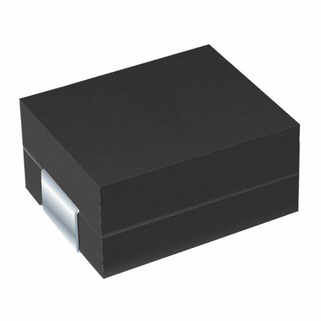
Shielded construction
Unit height of 4.2 mm
Inductance range: 0.10 μH to 0.22 μH
Current up to 35 A
RoHS compliant*
This series is currently available but
not recommended for new designs.
SRP8040 Series - Shielded Power Inductors
Electrical Specifications
Bourns Part No.
Inductance
L (μH)
IDC
(A)
RDC
(mΩ) max.
RDC
(mΩ) typ.
SRP8040-R10Y
SRP8040-R22Y
0.10 ± 30 %
0.22 ± 30 %
35.0
25.0
0.65
0.65
0.49
0.49
SRP8040-R10Y: IDC based on inductance drop 10 % typical of L value at 20 °C.
SRP8040-R22Y: IDC based on inductance drop 30 % typical of L value at 20 °C.
Materials
Core...............................................Ferrite
Wire ..................................Tinned copper
Terminal .........................................Cu/Sn
Rated Current
....................See Electrical Specifications
Temperature Rise..........40 ˚C at rated I rms
Packaging .....1000 pcs. per 13-inch reel
Soldering Profile
225
260 °C peak
255 °C
220 °C
190°C
60 seconds
maximum
175
Ramp Down
5 °C/second
150 °C
Product Dimensions
125
120-150 seconds
8.2 ± 0.30
(.323 ± .012)
10 seconds minimum
75
7.6 ± 0.15
(.299 ± .006)
Ramp Up
4 °C/second maximum
25
0
50
100
150
200
250
300
Time (Seconds)
6.10 ± 0.15
(.240 ± .006)
R10
Temperature (°C)
275
Maximum of 10 seconds
between +255 °C and +260 °C
General Specifications
Test Voltage.....................................1.0 V
Test Frequency ..........................100 KHz
Reflow Soldering .....230 ˚C; 50 sec max.
Operating Temperature ..-55 °C to +150 °C
(Temperature rise included)
Storage Temperature..-55 °C to +150 °C
Resistance to Soldering Heat
..............................+260 °C for 10 sec.
Electrical Schematic
4.20 ± 0.30
(.165 ± .012)
TYP.
TYP.
3.0
(0.118)
1.80
(.071)
Recommended Layout
2.4
(.094)
*RoHS Directive 2002/95/EC Jan 27 2003 including Annex.
Specifications are subject to change without notice. Users should verify actual device performance in their specific
applications. The products described herein and this document are subject to specific legal disclaimers as set forth on
the last page of this document, and at www.bourns.com/docs/legal/disclaimer.pdf
9.2
(.362)
4.4
(.173)
2.4
(.094)
6.8
(.268)
3.6
(.142)
DIMENSIONS:
MM
(INCHES)
�SRP8040 Series - Shielded Power Inductors
L vs. I Charts
40
0.06
0.04
0.02
0
20
0
10
20
30
Inductance (μH)
60
0.12
0.10
0.08
Temperature Rise (°C)
Inductance (μH)
80
0.14
0
50
40
SRP8040-R22Y
0.20
0.18
0.16
100
100
80
0.14
60
0.12
0.10
0.08
40
0.06
0.04
0.02
0
20
0
5
10
15
Temperature Rise (°C)
SRP8040-R10Y
0.20
0.18
0.16
0
25
20
DC Current (A)
DC Current (A)
Packaging Specifications
330.0
(13.00)
DIA.
2.0 ± 0.5
(.079 ± .020)
30.4
(1.20)
DIMENSIONS:
MM
(INCHES)
THICKNESS
0.10
(.004)
MAX.
13.0
(.51)
DIA.
EMBOSSED
CAVITY
50 - 0
(1.97 - 0)
13.0
DIA.
(.51)
EMBOSSED
CARRIER
26.0 + 0
(1.02 + 0)
12.0
(0.472)
END
R10
R10
4.0
(0.157)
R10
R10
R10
NO COMPONENT
160
(6.299)
R10
START
R10
NO COMPONENT
COMPONENTS
MIN.
400
(15.748)
MIN.
USER DIRECTION OF FEED
Tel: +886-2 2562-4117 • Email: asiacus@bourns.com
EMEA: Tel: +36 88 520 390 • Email: eurocus@bourns.com
The Americas: Tel: +1-951 781-5500 • Email: americus@bourns.com
www.bourns.com
REV. 06/17
Specifications are subject to change without notice.
Users should verify actual device performance in their specific applications.
The products described herein and this document are subject to specific legal disclaimers as set forth on the last page of this document, and at www.bourns.com/docs/legal/disclaimer.pdf.
�Legal Disclaimer Notice
This legal disclaimer applies to purchasers and users of Bourns® products manufactured by or on behalf of Bourns, Inc. and
P[Z�HɉSPH[LZ��JVSSLJ[P]LS`��¸)V\YUZ¹��
Unless otherwise expressly indicated in writing, Bourns® products and data sheets relating thereto are subject to change
^P[OV\[�UV[PJL���
很抱歉,暂时无法提供与“SRP8040-R22Y”相匹配的价格&库存,您可以联系我们找货
免费人工找货