1. 物料型号:
- TBU-CA025-xxx-WH
- TBU-CA040-xxx-WH
- TBU-CA050-xxx-WH
- TBU-CA065-xxx-WH
- TBU-CA085-xxx-WH
2. 器件简介:
- TBU-CA系列是Bourns® TBU®产品,采用MOSFET半导体技术制造的低电容单向高速保护组件,旨在保护因短路、交流电源交叉、感应和雷电浪涌引起的故障。
3. 引脚分配:
- Pad #1: Line In/Out
- Pad #2: NU(无连接)
- Pad #3: Line Out/In
4. 参数特性:
- 峰值脉冲电压承受能力(Vimp):250V至850V不等
- 连续交流RMS电压(Vrms):100V至425V不等
- 工作温度范围(Top):-40至+125°C
- 存储温度范围(Tstg):-65至+150°C
- 最大结温(Timax):+125°C
- HBM ESD保护:±2kV
5. 功能详解:
- TBU®高速保护器放置在系统电路中,通过MOSFET检测电路触发,为敏感电子设备提供有效的屏障,使其在浪涌事件中不会暴露在大电压或电流下。
- 设备在大约1微秒内操作,一旦线路电流超过TBU®设备的触发电流Itrigger,TBU®设备将限制线路电流通常小于1mA。
- 在浪涌后,当TBU®设备上的电压下降到Vreset水平时,TBU®设备将重置。
6. 应用信息:
- 语音/VDSL卡保护模块和dongles
- 过程控制设备
- 测试和测量设备
- 通用电子设备
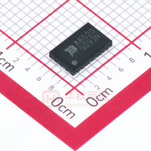
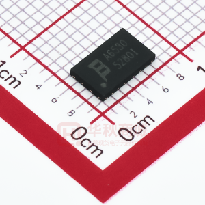
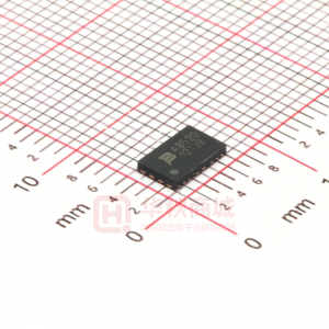
7. 封装信息:
- TBU®设备采用表面贴装DFN封装,并满足行业标准要求,如RoHS和无铅焊料回流曲线。