TIC106 SERIES
SILICON CONTROLLED RECTIFIERS
5 A Continuous On-State Current
30 A Surge-Current
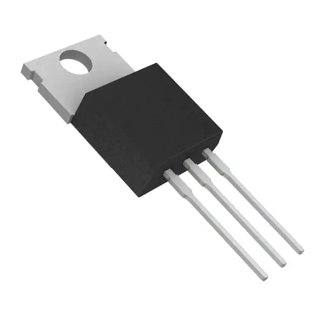
TO-220 PACKAGE
(TOP VIEW)
Glass Passivated Wafer
400 V to 800 V Off-State Voltage
K
1
Max IGT of 200 µA
A
2
G
3
This series is obsolete and
not recommended for new designs.
Pin 2 is in electrical contact with the mounting base.
MDC1ACA
absolute maximum ratings over operating case temperature (unless otherwise noted)
RATING
SYMBOL
Repetitive peak off-state voltage (see Note 1)
TIC106M
TIC106S
VDRM
E
T
E
L
O
S
B
O
TIC106N
TIC106D
Repetitive peak reverse voltage
Continuous on-state curr ent at (or below) 80°C case temperature (see Note 2)
TIC106M
TIC106S
TIC106N
Average on-state current (180° conduction angle) at (or below) 80°C case temperature
(see Note 3)
Surge on-state current at (or below) 25°C (see Note 4)
Peak positive gate current (pulse width ≤ 300 µs)
Peak gate power dissipation (pulse width ≤ 300 µ s)
Average gate power dissipation (see Note 5)
Operating case temperature range
Storage temperature range
Lead temperature 1.6 mm from case for 10 seconds
VALUE
UNIT
400
TIC106D
VRRM
IT(RMS)
IT(AV)
ITSM
600
700
800
400
600
700
800
V
5
A
3.2
A
30
IGM
0.2
PG(AV)
0.3
PGM
V
A
A
1.3
W
TC
-40 to +110
°C
TL
230
°C
Tstg
-40 to +125
W
°C
NOTES: 1. These values apply when the gate-cathode resistance RGK = 1 kΩ.
2. These values apply for continuous dc operation with resistive load. Above 80°C derate linearly to zero at 110°C.
3. This value may be applied continuously under single phase 50 Hz half-sine-wave operation with resistive load. Above 80°C derate
linearly to zero at 110°C.
4. This value applies for one 50 Hz half-sine-wave when the device is operating at (or below) the rated value of peak reverse volta ge
and on-state current. Surge may be repeated after the device has returned to original thermal equilibrium.
5. This value applies for a maximum averaging time of 20 ms.
APRIL 1971 - REVISED SEPTEMBER 2002
Specifications are subject to change without notice.
1
�TIC106 SERIES
SILICON CONTROLLED RECTIFIERS
electrical characteristics at 25°C case temperature (unless otherwise noted)
PARAMETER
IDRM
IRRM
IGT
VGT
IH
Repetitive peak
off-state current
Repetitive peak
reverse current
Gate trigger current
Gate trigger voltage
Holding current
TEST CONDITIONS
MIN
TYP
VT
dv/dt
NOTE
voltage
Critical rate of rise of
off-state voltage
RGK = 1 kΩ
TC = 110°C
400
µA
VR = rated VRRM
IG = 0
TC = 110°C
1
mA
VAA = 12 V
RL = 100 Ω
tp(g) ≥ 20 µs
200
µA
VAA = 12 V
RL = 100 Ω
TC = - 40°C
tp(g) ≥ 20 µs
RGK = 1 kΩ
VAA = 12 V
RL = 100 Ω
tp(g) ≥ 20 µs
RGK = 1 kΩ
VAA = 12 V
RL = 100 Ω
tp(g) ≥ 20 µs
RGK = 1 kΩ
VAA = 12 V
RGK = 1 kΩ
5
1.2
0.4
TC = 110°C
0.6
IT = 5 A
TC = - 40°C
8
mA
RGK = 1 kΩ
5
(See Note 6)
1.7
E
T
E
L
O
S
B
O
VD = rated VD
RGK = 1 kΩ
V
0.2
Initiating IT = 10 mA
VAA = 12 V
1
TC = 110°C
10
V
V/µs
6: This parameter must be measured using pulse techniques, tp = 300 µs, duty cycle ≤ 2 %. Voltage sensing-contacts, separate from
the current carrying contacts, are located within 3.2 mm from the device body.
thermal characteristics
PARAMETER
RθJC
Junction to case thermal resistance
RθJA
Junction to free air thermal resistance
MIN
������
2
UNIT
VD = rated VDRM
Initiating IT = 10 mA
Peak on-state
MAX
TYP
MAX
UNIT
3.5
°C/W
62.5
°C/W
�
�������
APRIL 1971 - REVISED SEPTEMBER 2002
Specifications are subject to change without notice.
�TIC106 SERIES
SILICON CONTROLLED RECTIFIERS
THERMAL INFORMATION
AVERAGE ANODE ON-STATE CURRENT
ANODE POWER DISSIPATED
vs
ON-STATE CURRENT
TI20AA
6
TJ = 110°C
Continuous DC
5
4
Φ = 180º
3
2
0°
Angle
0
30
10
E
T
E
L
O
S
B
O
180°
Φ
Conduction
1
1
40
50
60
70
80
90
100
110
1
10
100
TC - Case Temperature - °C
IT - On-State Current - A
Figure 1.
Figure 2.
SURGE ON-STATE CURRENT
vs
CYCLES OF CURRENT DURATION
TRANSIENT THERMAL RESISTANCE
vs
CYCLES OF CURRENT DURATION
TI20AC
100
10
RθJC(t) - Transient Thermal Resistance - °C/W
TC ≤ 80 °C
ITM - Peak Half-Sine-Wave Current - A
TI20AB
100
PA - Anode Power Dissipated - W
IT(AV) - Maximum Average Anode Forward Current - A
DERATING CURVE
No Prior Device Conduction
Gate Control Guaranteed
10
1
TI20AD
1
0·1
1
10
100
1
10
Consecutive 50 Hz Half-Sine-Wave Cycles
Consecutive 50 Hz Half-Sine-Wave Cycles
Figure 3.
Figure 4.
������
100
�
�������
APRIL 1971 - REVISED SEPTEMBER 2002
Specifications are subject to change without notice.
3
�TIC106 SERIES
SILICON CONTROLLED RECTIFIERS
TYPICAL CHARACTERISTICS
GATE TRIGGER VOLTAGE
vs
HOLDING CURRENT
vs
CASE TEMPERATURE
CASE TEMPERATURE
TC20AB
1
10
0·8
VAA = 12 V
RL = 100 Ω
RGK = 1 kΩ
RGK = 1 kΩ
Initiating IT = 10 mA
IH - Holding Current - mA
VGT - Gate Trigger Voltage - V
VAA = 12 V
tp(g) ≥ 20 µs
0·6
0·4
0·2
0
-50
-25
0
25
TC20AD
1
E
T
E
L
O
S
B
O
50
75
100
0.1
-50
125
-25
0
25
50
75
TC - Case Temperature - °C
TC - Case Temperature - °C
Figure 5.
Figure 6.
100
125
PEAK ON-STATE VOLTAGE
vs
PEAK ON-STATE CURRENT
TC20AE
VTM - Peak On-State Voltage - V
2.5
2.0
TC = 25 °C
t p = 300 µs
Duty Cycle ≤ 2 %
1.5
1.0
0.5
0.0
0·1
1
10
ITM - Peak On-State Current - A
Figure 7.
������
4
�
�������
APRIL 1971 - REVISED SEPTEMBER 2002
Specifications are subject to change without notice.
�
很抱歉,暂时无法提供与“TIC106S-S”相匹配的价格&库存,您可以联系我们找货
免费人工找货