TIC226 SERIES
SILICON TRIACS
8 A RMS
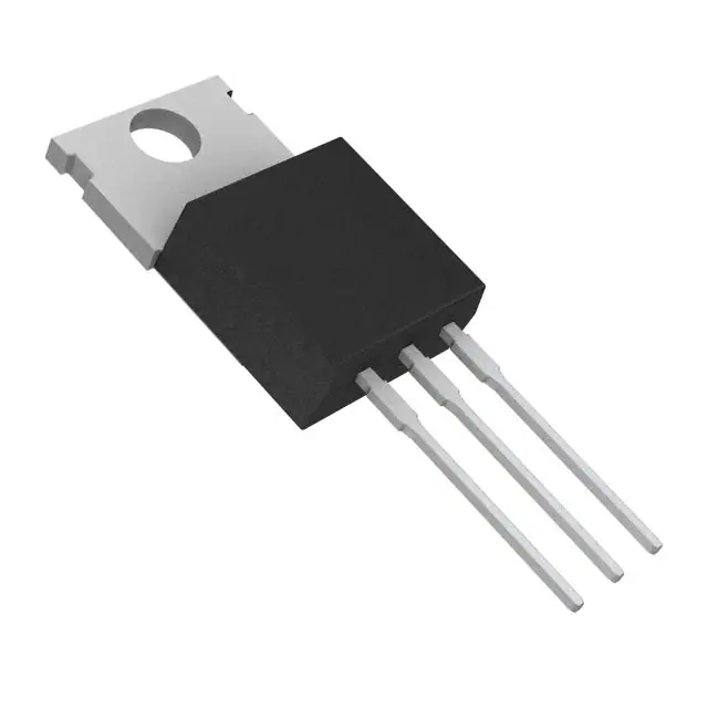
TO-220 PACKAGE
(TOP VIEW)
Glass Passivated Wafer
400 V to 800 V Off-State Voltage
MT1
1
Max IGT of 50 mA (Quadrants 1 - 3)
MT2
2
G
3
This series is currently available,
but not recommended for new
designs.
Pin 2 is in electrical contact with the mounting base.
absolute maximum ratings over operating case temperature (unless otherwise noted)
RATING
TIC226D
TIC226M
Repetitive peak off-state voltage (see Note 1)
TIC226S
Full-cycle RMS on-state current at (or below) 85°C case temperature (see Note 2)
TIC226N
Peak on-state surge current full-sine-wave at (or below) 25°C case temperature (see Note 3)
Peak gate current
Peak gate power dissipation at (or below) 85°C case temperature (pulse width ≤ 200 μs)
Average gate power dissipation at (or below) 85°C case temperature (see Note 4)
Operating case temperature range
Storage temperature range
SYMBOL
400
600
VDRM
800
8
ITSM
UNIT
V
700
IT(RMS)
A
70
A
PGM
2.2
W
TC
-40 to +110
°C
TL
230
°C
IGM
PG(AV)
Tstg
Lead temperature 1.6 mm from case for 10 seconds
VALUE
MDC2ACA
±1
A
0.9
-40 to +125
W
°C
NOTES: 1. These values apply bidirectionally for any value of resistance between the gate and Main Terminal 1.
2. This value applies for 50-Hz full-sine-wave operation with resistive load. Above 85°C derate linearly to 110°C case temperature at
the rate of 320 mA/°C.
3. This value applies for one 50-Hz full-sine-wave when the device is operating at (or below) the rated value of on-state current. Surge
may be repeated after the device has returned to original thermal equilibrium. During the surge, gate control may be lost.
4. This value applies for a maximum averaging time of 20 ms.
electrical characteristics at 25°C case temperature (unless otherwise noted )
PARAMETER
IDRM
IGT
VGT
VT
Repetitive peak
off-state current
Gate trigger
current
Gate trigger
voltage
On-state voltage
TEST CONDITIONS
VD = rated VDRM
IG = 0
Vsupply = +12 V†
RL = 10 Ω
Vsupply = -12 V†
RL = 10 Ω
Vsupply = +12 V†
Vsupply = -12 V†
RL = 10 Ω
tp(g) > 20 μs
Vsupply = -12 V†
RL = 10 Ω
Vsupply = -12 V†
IT = ±12 A
tp(g) > 20 μs
tp(g) > 20 μs
RL = 10 Ω
tp(g) > 20 μs
tp(g) > 20 μs
RL = 10 Ω
tp(g) > 20 μs
RL = 10 Ω
tp(g) > 20 μs
IG = 50 mA
TYP
TC = 110°C
RL = 10 Ω
Vsupply = +12 V†
Vsupply = +12 V†
MIN
tp(g) > 20 μs
(see Note 5)
6
-12
-10
25
0.7
-0.8
-0.8
0.9
±1.5
MAX
UNIT
±2
mA
50
-50
-50
mA
2
-2
-2
2
±2.1
V
V
† All voltages are with respect to Main Terminal 1.
APRIL 1971 - REVISED SEPTEMBER 2002
Specifications are subject to change without notice.
1
�TIC226 SERIES
SILICON TRIACS
electrical characteristics at 25°C case temperature (unless otherwise noted) (continued)
PARAMETER
TEST CONDITIONS
IH
Holding current
IL
Latching current
Init’ ITM = 100 mA
10
30
Vsupply = -12 V†
IG = 0
Init’ ITM = -100 mA
-6
-30
Vsupply = +12 V†
off-state voltage
dv/dt(c)
MAX
IG = 0
Critical rise of commutation voltage
MIN
VDRM = Rated VDRM
IG = 0
VDRM = Rated VDRM
ITRM = ±12 A
UNIT
mA
50
(see Note 6)
Vsupply = -12 V†
Critical rate of rise of
dv/dt
TYP
Vsupply = +12 V†
mA
-50
TC = 110°C
±100
TC = 85°C
V/µs
±5
V/µs
(see figure 7)
† All voltages are with respect to Main Terminal 1.
NOTES: 5. This parameter must be measured using pulse techniques, t p = ≤ 1 ms, duty cycle ≤ 2 %. Voltage-sensing contacts separate from
the current carrying contacts are located within 3.2 mm from the device body.
6. The triacs are triggered by a 15-V (open-circuit amplitude) pulse supplied by a generator with the following characteristics:
R G = 100 Ω, tp(g) = 20 µs, tr = ≤ 15 ns, f = 1 kHz.
thermal characteristics
PARAMETER
RθJC
Junction to case thermal resistance
RθJA
Junction to free air thermal resistance
MIN
TYP
MAX
UNIT
1.8
°C/W
62.5
°C/W
TYPICAL CHARACTERISTICS
GATE TRIGGER CURRENT
vs
CASE TEMPERATURE
CASE TEMPERATURE
TC01AA
Vsupply IGTM
VAA = ± 12 V
+
+
-
RL = 10 Ω
tp(g) = 20 µs
+
+
100
10
1
-60
-40
-20
0
20
40
60
80
100
120
TC01AB
10
VAA = ± 12 V
Vsupply IGTM
VGT - Gate Trigger Voltage - V
IGT - Gate Trigger Current - mA
1000
GATE TRIGGER VOLTAGE
vs
+
+
-
+
-
-
+
RL = 10 Ω
tp(g) = 20 µs
}
1
0·1
-60
-40
-20
0
20
60
80
TC - Case Temperature - °C
TC - Case Temperature - °C
Figure 1.
Figure 2.
������
2
40
100
120
�
�������
APRIL 1971 - REVISED SEPTEMBER 2002
Specifications are subject to change without notice.
�TIC226 SERIES
SILICON TRIACS
TYPICAL CHARACTERISTICS
HOLDING CURRENT
vs
LATCHING CURRENT
vs
CASE TEMPERATURE
1000
VAA = ± 12 V
Vsupply
+
-
Vsupply IGTM
IG = 0
Initiating ITM = 100 mA
IL - Latching Current - mA
IH - Holding Current - mA
CASE TEMPERATURE
TC01AD
1000
100
10
+
+
-
+
+
-20
0
TC01AE
VAA = ± 12 V
100
10
1
0·1
-60
-40
-20
0
20
40
60
80
100
1
-60
120
-40
TC - Case Temperature - °C
20
40
60
80
100
120
TC - Case Temperature - °C
Figure 3.
Figure 4.
THERMAL INFORMATION
MAX AVERAGE POWER DISSIPATED
vs
MAX RMS ON-STATE CURRENT
vs
CASE TEMPERATURE
RMS ON-STATE CURRENT
TI01AB
P(av) - Maximum Average Power Dissipated - W
IT(RMS) - Maximum On-State Current - A
10
9
8
7
6
5
4
3
2
1
0
32
TI01AC
TJ = 110 °C
28
Conduction Angle = 360 °
Above 8 A rms
See ITSM Figure
24
20
16
12
8
4
0
0
25
50
75
100
125
0
2
4
6
8
10
12
TC - Case Temperature - °C
IT(RMS) - RMS On-State Current - A
Figure 5.
Figure 6.
������
14
16
�
�������
APRIL 1971 - REVISED SEPTEMBER 2002
Specifications are subject to change without notice.
3
�TIC226 SERIES
SILICON TRIACS
PARAMETER MEASUREMENT INFORMATION
VAC
VAC
L1
ITRM
IMT2
IMT2
C1
50 Hz
VMT2
VDRM
DUT
RG
See
Note A
R1
VMT2
10%
dv/dt
63%
IG
IG
NOTE A: The gate-current pulse is furnished by a trigger circuit which presents essentially an open circuit between pulses. The pulse is timed
so that the off-state-voltage duration is approximately 800 µs.
PMC2AA
Figure 7.
������
4
�
�������
APRIL 1971 - REVISED SEPTEMBER 2002
Specifications are subject to change without notice.
�
很抱歉,暂时无法提供与“TIC226M-S”相匹配的价格&库存,您可以联系我们找货
免费人工找货