TISP2290
DUAL SYMMETRICAL TRANSIENT
VOLTAGE SUPPRESSORS
Copyright © 1997, Power Innovations Limited, UK
NOVEMBER 1986 - REVISED SEPTEMBER 1997
TELECOMMUNICATION SYSTEM SECONDARY PROTECTION
●
Ion-Implanted Breakdown Region
Precise and Stable Voltage
Low Voltage Overshoot under Surge
DEVICE
‘2290
●
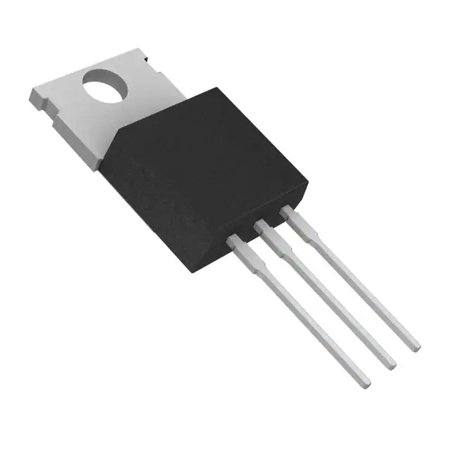
TO-220 PACKAGE
(TOP VIEW)
V(BO)
A(T)
1
V
V
C(G)
2
200
290
B(R)
3
V(Z)
Planar Passivated Junctions
Low Off-State Current < 10 µA
Pin 2 is in electrical contact with the mounting base.
MDXXANA
●
Rated for International Surge Wave Shapes
WAVE SHAPE
STANDARD
8/20 µs
ANSI C62.41
A
150
10/160 µs
FCC Part 68
60
10/560 µs
FCC Part 68
45
0.2/310 µs
RLM 88
38
FTZ R12
50
10/700 µs
VDE 0433
50
CCITT IX K17/K20
50
REA PE-60
50
10/1000 µs
●
ITSP
device symbol
UL Recognized, E132482
description
The TISP2290 is designed specifically for
telephone equipment protection against lightning
and transients induced by a.c. power lines.
These devices will supress voltage transients
between terminals A and C, B and C, and A and
B.
Transients are initially clipped by zener action
until the voltage rises to the breakover level,
which causes the device to crowbar. The high
crowbar holding current prevents d.c. latchup as
the transient subsides.
PRODUCT
These monolithic protection devices are
fabricated in ion-implanted planar structures to
ensure precise and matched breakover control
and are virtually transparent to the system in
normal operation.
INFORMATION
Information is current as of publication date. Products conform to specifications in accordance
with the terms of Power Innovations standard warranty. Production processing does not
necessarily include testing of all parameters.
1
�TISP2290
DUAL SYMMETRICAL TRANSIENT
VOLTAGE SUPPRESSORS
NOVEMBER 1986 - REVISED SEPTEMBER 1997
absolute maximum ratings at 25°C case temperature (unless otherwise noted)
RATING
SYMBOL
VALUE
UNIT
Non-repetitive peak on-state pulse current (see Notes 1, 2 and 3)
8/20 µs (ANSI C62.41, open-circuit voltage wave shape 1.2/50 µs)
150
10/160 µs (FCC Part 68, open-circuit voltage wave shape 10/160 µs)
60
5/200 µs (VDE 0433, open-circuit voltage wave shape 2 kV, 10/700 µs)
50
ITSP
0.2/310 µs (RLM 88, open-circuit voltage wave shape 1.5 kV, 0.5/700 µs)
A
38
5/310 µs (CCITT IX K17/K20, open-circuit voltage wave shape 2 kV, 10/700 µs)
50
5/310 µs (FTZ R12, open-circuit voltage wave shape 2 kV, 10/700 µs)
50
10/560 µs (FCC Part 68, open-circuit voltage wave shape 10/560 µs)
45
10/1000 µs (REA PE-60, open-circuit voltage wave shape 10/1000 µs)
50
Non-repetitive peak on-state current, 50 Hz, 2.5 s (see Notes 1 and 2)
ITSM
10
A rms
Initial rate of rise of on-state current,
diT/dt
250
A/µs
TJ
150
°C
0 to 70
°C
Linear current ramp, Maximum ramp value < 38 A
Junction temperature
Operating free - air temperature range
Storage temperature range
Tstg
-40 to +150
°C
Lead temperature 1.5 mm from case for 10 s
Tlead
260
°C
NOTES: 1. Above 70°C, derate linearly to zero at 150°C case temperature
2. This value applies when the initial case temperature is at (or below) 70°C. The surge may be repeated after the device has
returned to thermal equilibrium.
3. Most PTT’s quote an unloaded voltage waveform. In operation the TISP essentially shorts the generator output. The resulting
loaded current waveform is specified.
.
electrical characteristics for the A and B terminals, TJ = 25°C
PARAMETER
VZ
ID
Coff
NOTE
TEST CONDITIONS
Reference zener
MIN
IZ = ± 1mA
voltage
Off-state leakage
TYP
± 200
Off-state capacitance
VD = 0
f = 1 kHz
(see Note 4)
UNIT
V
VD = ± 50 V
current
MAX
40
± 10
µA
100
pF
4: These capacitance measurements employ a three terminal capacitance bridge incorporating a guard circuit. The third terminal is
connected to the guard terminal of the bridge.
electrical characteristics for the A and C or the B and C terminals, TJ = 25°C
PARAMETER
VZ
∝
VZ
TEST CONDITIONS
Reference zener
IZ = ± 1mA
voltage
Breakover voltage
(see Notes 5 and 6)
I(BO)
Breakover current
(see Note 5)
VTM
Peak on-state voltage
IT = ± 5 A
Holding current
(see Note 5)
dv/dt
ID
Coff
off-state voltage
Off-state leakage
current
Off-state capacitance
MAX
%/oC
± 290
± 0.15
± 1.9
(see Notes 5 and 6)
UNIT
V
0.1
of reference voltage
Critical rate of rise of
TYP
± 200
Temperature coefficient
V(BO)
IH
MIN
V
± 0.6
A
± 3
V
± 150
mA
(see Note 7)
± 5
kV/µs
VD = ± 50 V
± 10
µA
200
pF
VD = 0
f = 1 kHz
(see Note 4)
110
NOTES: 5. These parameters must be measured using pulse techniques, tw = 100 µs, duty cycle ≤ 2%.
6. These parameters are measured with voltage sensing contacts seperate from the current carrying contacts located within 3.2 mm
(0.125 inch) from the device body.
7. Linear rate of rise, maximum voltage limited to 80 % VZ (minimum)..
PRODUCT
2
INFORMATION
�TISP2290
DUAL SYMMETRICAL TRANSIENT
VOLTAGE SUPPRESSORS
NOVEMBER 1986 - REVISED SEPTEMBER 1997
PARAMETER MEASUREMENT INFORMATION
Figure 1. VOLTAGE-CURRENT CHARACTERISTIC FOR ANY PAIR OF TERMINALS
The high level characteristics for terminals A and B are not guaranteed.
thermal characteristics
PARAMETER
RθJA
Junction to free air thermal resistance
PRODUCT
MIN
TYP
MAX
UNIT
62.5
°C/W
INFORMATION
3
�TISP2290
DUAL SYMMETRICAL TRANSIENT
VOLTAGE SUPPRESSORS
NOVEMBER 1986 - REVISED SEPTEMBER 1997
TYPICAL CHARACTERISTICS
A and C, or B and C terminals
ON-STATE CURRENT
vs
ON-STATE VOLTAGE
VZ, V(BO) - Zener Voltage, Breakover Voltage - V
100
10
1
1
10
VT - On-State Voltage - V
Figure 2.
PRODUCT
4
JUNCTION TEMPERATURE
TCS2HAA
1000
IT - On-State Current - A
ZENER VOLTAGE & BREAKOVER VOLTAGE
vs
INFORMATION
100
290
TCS2HAB
280
V(BO)
270
260
VZ
250
240
230
220
210
200
-25
0
25
50
75
100
TJ - Junction Temperature - °C
Figure 3.
125
150
�TISP2290
DUAL SYMMETRICAL TRANSIENT
VOLTAGE SUPPRESSORS
NOVEMBER 1986 - REVISED SEPTEMBER 1997
TYPICAL CHARACTERISTICS
A and C, or B and C terminals
HOLDING CURRENT & BREAKOVER CURRENT
vs
JUNCTION TEMPERATURE
TCS2HAC
10
I(BO)
TCS2HAD
VD = ±50 V
ID - Off-State Current - µA
IH , I(BO) - Holding Current, Breakover Current - A
JUNCTION TEMPERATURE
1
OFF-STATE CURRENT
vs
IH
0·1
1
0·1
0·01
0·01
-25
0
25
50
75
100
125
0·001
-25
150
TJ - Junction Temperature - °C
0
25
50
75
100
125
150
TJ - Junction Temperature - °C
Figure 4.
Figure 5.
ON-STATE VOLTAGE
vs
JUNCTION TEMPERATURE
3.0
NORMALISED BREAKOVER VOLTAGE
vs
RATE OF RISE OF PRINCIPLE CURRENT
TCS2HAE
TCS2HAI
1.4
IT = ±5A
Normalised Breakover Voltage
VT - On-State Voltage - V
2.5
2.0
1.5
1.0
1.3
1.2
1.1
0.5
0.0
-25
0
25
50
75
100
125
TJ - Junction Temperature - °C
Figure 6.
PRODUCT
150
1.0
0·001
0·01
0·1
1
10
100
di/dt - Rate of Rise of Principle Current - A/µs
Figure 7.
INFORMATION
5
�TISP2290
DUAL SYMMETRICAL TRANSIENT
VOLTAGE SUPPRESSORS
NOVEMBER 1986 - REVISED SEPTEMBER 1997
TYPICAL CHARACTERISTICS
A and C, or B and C terminals
OFF-STATE CAPACITANCE
vs
TERMINAL VOLTAGE (POSITIVE)
TERMINAL VOLTAGE (NEGATIVE)
TCS2HAK
Third terminal bias = -50 V
100
Third terminal bias = 0 V
10
Third terminal bias = +50 V
1
0·1
1
TCS2HAL
1000
Off-State Capacitance - pF
1000
Off-State Capacitance - pF
OFF-STATE CAPACITANCE
vs
Third terminal bias = -50 V
100
Third terminal bias = 0 V
10
Third terminal bias = +50 V
10
100
1
0·1
Terminal Voltage (Positive) - V
1
Terminal Voltage (Negative) - V
Figure 8.
Figure 9.
SURGE CURRENT
vs
DECAY TIME
1000
Maximum Surge Current - A
10
TCS2HAO
100
10
2
10
100
Decay Time - µs
Figure 10.
PRODUCT
6
INFORMATION
1000
100
�TISP2290
DUAL SYMMETRICAL TRANSIENT
VOLTAGE SUPPRESSORS
NOVEMBER 1986 - REVISED SEPTEMBER 1997
TYPICAL CHARACTERISTICS
A and B terminals
ZENER VOLTAGE & BREAKOVER VOLTAGE
vs
280
JUNCTION TEMPERATURE
TCS2HAF
V(BO)
270
260
VZ
250
240
230
220
210
200
-25
0
25
50
75
100
1
IH , I(BO) - Holding Current, Breakover Current - A
VZ, V(BO) - Zener Voltage, Breakover Voltage - V
JUNCTION TEMPERATURE
290
HOLDING CURRENT & BREAKOVER CURRENT
vs
125
I(BO)
IH
0·1
IH
I(BO)
0·01
-25
150
TCS2HAG
0
25
TJ - Junction Temperature - °C
50
75
100
125
150
TJ - Junction Temperature - °C
Figure 11.
Figure 12.
OFF-STATE CURRENT
vs
JUNCTION TEMPERATURE
ID - Off-State Current - µA
10
1
TCS2HAH
VD
V
D = ±50 V
0·1
0·01
0·001
-25
0
25
50
75
100
125
150
TJ - Junction Temperature - °C
Figure 13.
PRODUCT
INFORMATION
7
�TISP2290
DUAL SYMMETRICAL TRANSIENT
VOLTAGE SUPPRESSORS
NOVEMBER 1986 - REVISED SEPTEMBER 1997
TYPICAL CHARACTERISTICS
A and B terminals
NORMALISED BREAKOVER VOLTAGE
vs
RATE OF RISE OF PRINCIPLE CURRENT
TCS2HAJ
2.5
TCS2HAM
1000
2.3
Off-State Capacitance - pF
Normalised Breakover Voltage
OFF-STATE CAPACITANCE
vs
TERMINAL VOLTAGE (POSITIVE)
2.0
1.8
1.5
100
Third terminal bias = -50 V
Third terminal bias = 0 V
10
1.3
Third terminal bias = +50 V
1.0
0·001
0·01
0·1
1
10
100
1
0·1
di/dt - Rate of Rise of Principle Current - A/µs
1
10
Terminal Voltage (Positive) - V
Figure 14.
Figure 15.
OFF-STATE CAPACITANCE
vs
TERMINAL VOLTAGE (NEGATIVE)
TCS2HAN
Off-State Capacitance - pF
1000
100
Third terminal bias = -50 V
10
Third terminal bias = 0 V
Third terminal bias = +50 V
1
0·1
1
10
Terminal Voltage (Negative) - V
Figure 16.
PRODUCT
8
INFORMATION
100
100
�TISP2290
DUAL SYMMETRICAL TRANSIENT
VOLTAGE SUPPRESSORS
NOVEMBER 1986 - REVISED SEPTEMBER 1997
THERMAL INFORMATION
MAXIMUM NON-RECURRENT 50Hz CURRENT
vs
CURRENT DURATION
THERMAL RESPONSE
TIS2MAA
IRMS - Maximum Non-Recurrent 50Hz Current - A
Zθ JA - Transient Thermal Impedance - °C/W
100
10
1
0·1
0·0001
0·001
0·01
0·1
1
10
100
TIS2MAB
10
1
0·1
VGEN = 250 VRMS
RGEN = 20 TO 1000 ohms
TAMB = 70°C
0·01
0·01
1000
0·1
t - Power Pulse Duration - s
1
10
100
t - Current Duration - s
Figure 17.
Figure 18.
FREE AIR TEMPERATURE
DERATING CURVE
TIS2MAC
Percent of Rated Power - %
100
80
60
40
20
0
25
50
75
100
125
150
TA - Free Air Temperature - °C
Figure 19.
PRODUCT
INFORMATION
9
�TISP2290
DUAL SYMMETRICAL TRANSIENT
VOLTAGE SUPPRESSORS
NOVEMBER 1986 - REVISED SEPTEMBER 1997
MECHANICAL DATA
TO-220
3-pin plastic flange-mount package
This single-in-line package consists of a circuit mounted on a lead frame and encapsulated within a plastic
compound. The compound will withstand soldering temperature with no deformation, and circuit performance
characteristics will remain stable when operated in high humidity conditions. Leads require no additional
cleaning or processing when used in soldered assembly.
TO220
4,70
4,20
ø
10,4
10,0
3,96
3,71
1,32
1,23
2,95
2,54
see Note B
6,6
6,0
15,90
14,55
see Note C
6,1
3,5
1,70
1,07
0,97
0,61
1
2
14,1
12,7
3
2,74
2,34
5,28
4,88
VERSION 1
0,64
0,41
2,90
2,40
VERSION 2
ALL LINEAR DIMENSIONS IN MILLIMETERS
NOTES: A. The centre pin is in electrical contact with the mounting tab.
B. Mounting tab corner profile according to package version.
C. Typical fixing hole centre stand off height according to package version.
Version 1, 18.0 mm. Version 2, 17.6 mm.
PRODUCT
10
INFORMATION
MDXXBE
�TISP2290
DUAL SYMMETRICAL TRANSIENT
VOLTAGE SUPPRESSORS
NOVEMBER 1986 - REVISED SEPTEMBER 1997
IMPORTANT NOTICE
Power Innovations Limited (PI) reserves the right to make changes to its products or to discontinue any
semiconductor product or service without notice, and advises its customers to verify, before placing orders, that the
information being relied on is current.
PI warrants performance of its semiconductor products to the specifications applicable at the time of sale in
accordance with PI's standard warranty. Testing and other quality control techniques are utilized to the extent PI
deems necessary to support this warranty. Specific testing of all parameters of each device is not necessarily
performed, except as mandated by government requirements.
PI accepts no liability for applications assistance, customer product design, software performance, or infringement
of patents or services described herein. Nor is any license, either express or implied, granted under any patent
right, copyright, design right, or other intellectual property right of PI covering or relating to any combination,
machine, or process in which such semiconductor products or services might be or are used.
PI SEMICONDUCTOR PRODUCTS ARE NOT DESIGNED, INTENDED, AUTHORIZED, OR WARRANTED TO BE
SUITABLE FOR USE IN LIFE-SUPPORT APPLICATIONS, DEVICES OR SYSTEMS.
Copyright © 1997, Power Innovations Limited
PRODUCT
INFORMATION
11
�