oH
S
CO
M
PL
IA
NT
TISP4070L3BJ, TISP4350L3BJ
*R
BIDIRECTIONAL THYRISTOR OVERVOLTAGE PROTECTORS
TISP4xxxL3BJ Overvoltage Protector Series
MODEM Protection against:
- TIA/EIA-IS-968 Type A & B surge
(formally FCC Part 68)
- UL 60950, Clause 6. power cross
- CSA 22.2 No. 60950, Clause 6. power cross
Ring-Tip Protection
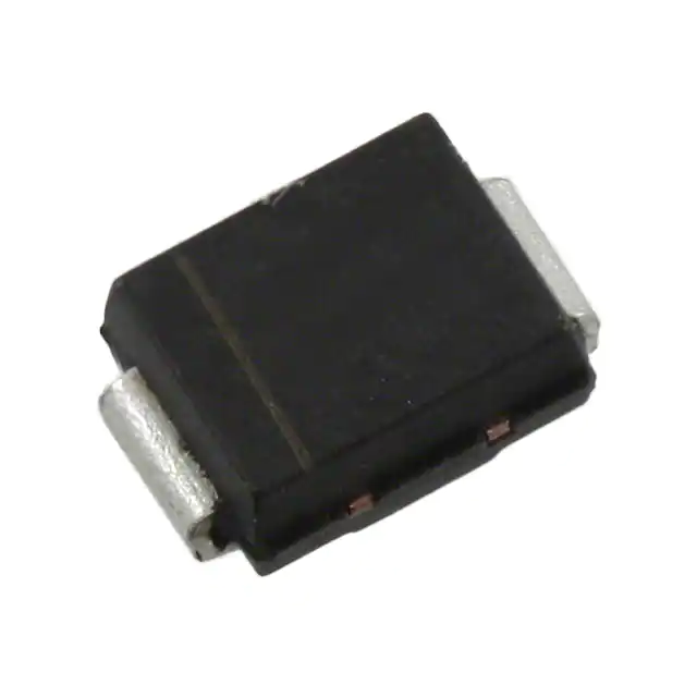
SMBJ Package (Top View)
R(B) 1
..........................TISP4350L3BJ
2
T(A)
Electronics Protection..........................TISP4070L3BJ
MDXXBGE
Ion-Implanted Breakdown Region
Precise and Stable Voltage
Low Voltage Overshoot under Surge
Device
‘4070
‘4350
VDRM
V(BO)
V
58
275
V
70
350
Device Symbol
T
Rated for ‘60950 and ‘968 Wave Shapes
Surge
Type
Wave
Shape
Standard
A
10/160 µs
TIA/EIA-IS-968 (FCC Part 68)
10/560 µs
B
TIA/EIA-IS-968 (FCC Part 68) 9/720 µs
10/700 µs
UL 60950 / ITU-T K.21
ITSP
SD4XAA
R
A
50
30
Terminals T and R correspond to the
alternative line designators of A and B
40
............................................ UL Recognized Components
Description
These devices are designed to limit overvoltages on the telephone line. Overvoltages are normally caused by a.c. power system or lightning
flash disturbances which are induced or conducted on to the telephone line. A single device provides 2-point protection and is typically used
for the protection of 2-wire telecommunication equipment (e.g. between the Ring and Tip wires for telephones and modems). Combinations of
devices can be used for multi-point protection (e.g. 3-point protection between Ring, Tip and Ground).
The protector consists of a symmetrical voltage-triggered bidirectional thyristor. Overvoltages are initially clipped by breakdown clamping until
the voltage rises to the breakover level, which causes the device to crowbar into a low-voltage on state. This low-voltage on state causes the
current resulting from the overvoltage to be safely diverted through the device. The high crowbar holding current prevents d.c. latchup as the
diverted current subsides. These protectors are guaranteed to voltage limit and withstand the listed lightning surges in both polarities.
After a Type A surge the equipment can be non-operational or operational. An operational pass requires the two high current Type A surges
(200 A, 10/160, and 100A, 10/560), to be reduced to within the TISP4xxxL3BJ ratings (50 A, 10/160 and 30 A, 10/560).
How To Order
Device
Package
Carrier
Order As
TISP4xxxL3BJ
BJ (J-Bend DO-214AA/SMB)
Embossed Tape Reeled
TISP4xxxL3BJR-S
Insert xxx value corresponding to protection voltages of 070 and 350
After a Type B surge, the equipment must be operational. As the TISP4xxxL3BJ has a current rating of 40 A, it will survive both Type B surges,
metallic (25 A, 9/720) and longitudinal (37.5 A, 9/720), giving an operational pass to Type B surges.
*RoHS Directive 2002/95/EC Jan 27 2003 including Annex
AUGUST 1999 - REVISED JANUARY 2007
Specifications are subject to change without notice.
Customers should verify actual device performance in their specific applications.
�TISP4xxxL3BJ Overvoltage Protector Series
Description (continued)
For metallic protection, the TISP4350L3BJ is connected between the Ring and Tip conductors. For longitudinal protection, two TISP4350L3BJ
protectors are used; one between the Ring conductor to ground and the other between the Tip conductor to ground. The B type ringer has
voltages of 56.5 V d.c. and up to 150 V r.m.s. a.c., giving a peak voltage of 269 V. The TISP4350L3BJ will not clip the B type ringing voltage as
it has a high impedance up to 275 V.
The TISP4070L3BJ should be connected after the hook switch to protect the following electronics. As the TISP4070L3BJ has a high
impedance up to 58 V, it will switch off after a surge and not be triggered by the normal exchange battery voltage.
These low (L) current protection devices are in a plastic package SMBJ (JEDEC DO-214AA with J-bend leads) and supplied in embossed tape
reel pack. For alternative voltage and holding current values, consult the factory. For higher rated impulse currents in the SMB package, the
100 A 10/1000 TISP4xxxH3BJ series is available.
Absolute Maximum Ratings, TA = 25 °C (Unless Otherwise Noted)
Rating
Repetitive peak off-state voltage
Symbol
‘4070
‘4350
Non-repetitive peak on-state pulse current (see Notes 1, and 2)
10/160 µs (FCC Part 68, 10/160 µs voltage wave shape, Type A)
5/310 µs (ITU-T K.21, 10/700 µs voltage wave shape)
5/320 µs (FCC Part 68, 9/720 µs voltage wave shape, Type B)
10/560 µs (FCC Part 68, 10/560 µs voltage wave shape, Type A)
Non-repetitive peak on-state current (see Notes 1, 2 and 3)
20 ms (50 Hz) full sine wave
16.7 ms (60 Hz) full sine wave
1000 s 50 Hz/60 Hz a.c.
Initial rate of rise of on-state current, Exponential current ramp, Maximum ramp value < 100 A
Junction temperature
Storage temperature range
VDRM
ITSP
Value
± 58
±275
50
40
40
30
Unit
V
A
ITSM
12
13
2
A
diT/dt
TJ
Tstg
120
-40 to +150
-65 to +150
A/µs
°C
°C
NOTES: 1. Initially the TISP4xxxL3BJ must be in thermal equilibrium with TJ = 25 °C.
2. The surge may be repeated after the TISP4xxxL3BJ returns to its initial conditions.
3. EIA/JESD51-2 environment and EIA/JESD51-3 PCB with standard footprint dimensions connected with 5 A rated printed wiring
track widths. Derate current values at -0.61 %/°C for ambient temperatures above 25 °C.
Overload Ratings, T A = 25 °C (Unless Otherwise Noted)
Rating
Peak overload on-state current, Type A impulse (see Note 4)
10/160 µs
10/560 µs
Peak overload on-state current, a.c. power cross tests UL 1950 (see Note 4)
NOTE
Symbol
Value
Unit
IT(OV)M
200
100
A
IT(OV)M
See Figure 2
for current
versus time
A
4: These electrical stress levels may damage the TIS4xxxL3BJ silicon chip. After test, the pass criterion is either that the device is
functional or, if it is faulty, that it has a short circuit fault mode. In the short circuit fault mode, the following equipment is
protected as the device is a permanent short across the line. The equipment would be unprotected if an open circuit fault mode
developed.
AUGUST 1999 - REVISED JANUARY 2007
Specifications are subject to change without notice.
Customers should verify actual device performance in their specific applications.
�TISP4xxxL3BJ Overvoltage Protector Series
Electrical Characteristics for the R and T Terminals, TA = 25 °C (Unless Otherwise Noted)
IDRM
Parameter
Repetitive peak offstate current
VD = VDRM
V(BO)
Breakover voltage
dv/dt = ±250 V/ms, RSOURCE = 300 Ω
V(BO)
Impulse breakover
voltage
I(BO)
VT
IH
dv/dt
ID
Coff
Breakover current
On-state voltage
Holding current
Critical rate of rise of
off-state voltage
Off-state current
Off-state capacitance
Test Conditions
TA = 25 °C
TA = 85 °C
‘4070
‘4350
Min
Max
±5
±10
±70
±350
‘4070
‘4350
±78
±359
V
±250
±3
±350
mA
V
mA
dv/dt ≤ ±1000 V/µs, Linear voltage ramp,
Maximum ramp value = ±500 V
di/dt = ±20 A/µs, Linear current ramp,
Maximum ramp value = ±10 A
dv/dt = ±250 V/ms, RSOURCE = 300 Ω
IT = ±5 A, tW = 100 µs
IT = ±5 A, di/dt = -/+ 30 mA/ms
±40
±120
Linear voltage ramp, Maximum ramp value < 0.85VDRM
VD = ±50 V
f = 100 kHz, Vd = 1 V rms,
f = 100 kHz, Vd = 1 V rms,
Typ
‘4350
µA
V
kV/µs
±5
TA = 85 °C
‘4070
VD = 0
VD = 1 V
VD = 5 V
VD = 0
VD = 1 V
VD = 5 V
Unit
±10
50
48
39
33
30
25
µA
40
38
31
26
24
20
Typ
Max
Unit
pF
Thermal Characteristics
Parameter
RθJA
NOTE
Junction to free air thermal resistance
Test Conditions
Min
EIA/JESD51-3 PCB, IT = ITSM(1000),
TA = 25 °C, (see Note 5)
265 mm x 210 mm populated line card,
4-layer PCB, IT = ITSM(1000), TA = 25 °C
115
° C /W
52
5: EIA/JESD51-2 environment and PCB has standard footprint dimensions connected with 5 A rated printed wiring track widths.
AUGUST 1999 - REVISED JANUARY 2007
Specifications are subject to change without notice.
Customers should verify actual device performance in their specific applications.
�TISP4xxxL3BJ Overvoltage Protector Series
Parameter Measurement Information
+i
Quadrant I
ITSP
Switching
Characteristic
ITSM
IT
V(BO)
VT
I(BO)
IH
VDRM
-v
IDRM
ID
VD
ID
IDRM
VD
VDRM
+v
IH
I(BO)
VT
V(BO)
IT
ITSM
Quadrant III
ITSP
Switching
Characteristic
-i
Figure 1. Voltage-current Characteristic for T and R Terminals
All Measurements are Referenced to the R Terminal
AUGUST 1999 - REVISED JANUARY 2007
Specifications are subject to change without notice.
Customers should verify actual device performance in their specific applications.
PMXXAAB
�TISP4xxxL3BJ Overvoltage Protector Series
Thermal Information
IT(OV)M — Peak Overload On-State Current — A rms
PEAK OVERLOAD ON-STATE CURRENT
vs
CURRENT DURATION
TI4LAA
40
35
30
25
100 A2s
40 A
20
TISP4xxxL3BJ WILL
CARRY CURRENT
OF TESTS 1 THRU 5
CLAUSE 6.6, UL 1950,
FOR FULL TEST TIME
15
7A
10
9
8
7
6
5
4
3.5
3
2.5
2
0·01
2.2 A
WIRING
SIMULATOR
0·1
1
10
100
t - Current Duration - s
1000
Figure 2. Peak Overload On-state Current against Duration
AUGUST 1999 - REVISED JANUARY 2007
Specifications are subject to change without notice.
Customers should verify actual device performance in their specific applications.
�TISP4xxxL3BJ Overvoltage Protector Series
APPLICATIONS INFORMATION
FCC Part 68, ACTA, TIA and EIA
From 2001, the registrations for FCC equipment changed from the FCC to ACTA, Administrative Council for Terminal Attachments. For this
function, ACTA needed to adopt a US National standard specifying terminal equipment requirements. The TIA, Telecommunications Industry
Association, in conjunction with the EIA, Electronic Industries Alliance, created TIA/EIA-IS-968 for this purpose. The first issue of TIA/EIA-IS-968
is essentially a renumbered version of the FCC Part 68 requirement. Clause and figure changes are shown in the table.
Item
Telephone Line Surge – Type A
FCC Part 68
TIA/EIA-IS-968
Clause 68.302 (b)
Clause 4.2.2
Telephone Line Surge – Type B
Clause 68.302 (c)
Clause 4.2.3
Simplified Surge Generator
Fig. 68.302 (a)
Figure 4.1
Open Circuit voltage Wave shape
Fig. 68.302 (b)
Figure 4.2
Short Circuit Current Wave shape
Fig. 68.302 (c)
Figure 4.3
TIA/EIA-IS-968 (FCC Part 68) Impulse Testing
To verify the withstand capability and safety of the equipment, standards require that the equipment is tested with various impulse wave forms.
The table below shows values for the TIA/EIA-IS-968 and ITU-T recommendation K.21.
Standard
Test
Peak
Voltage
Peak
Current
Fictive
TISP4xxxL3
Series
Condition
Voltage
Wave Form
Current
Wave Form
Impedance
Rating
Resistance
V
V
µs
A
µs
Ω
A
Ω
Longitudinal
1500
10/160
200
10/160
7.5
50
2 x 24
TIA/EIA-IS-968
Metallic
800
10/560
100
10/560
8
30
19
(F CC Part 68)
Longitudinal
1500
9/720 †
37.5
5/320 †
40
40
0
Metallic
1000
9/720 †
25
5/320 †
40
40
ITU-T K.21 ‡
Basic Level
ITU-T K.21 ‡
Enhanced Level
Transverse
Transverse
1500
4000
1500
6000
10/700
10/700
37.5
100
37.5
125
5/310
40
30
5/310
40
30
0
0
10
0
10
† TIA/EIA-IS-968 terminology for the wave forms produced by the ITU-T recommendation K.21 10/700 impulse generator
‡ Values assume the TISP4xxxL3 is connected inter-conductor and a 400 V primary is used
If the impulse generator current exceeds the protector’s current rating then a series resistance can be used to reduce the current to the
protector’s rated value to prevent possible failure. The required value of series resistance for a given wave form is given by the following
calculations. First, the minimum total circuit impedance is found by dividing the impulse generator’s peak voltage by the protector’s rated
current. The impulse generator’s fictive impedance (generator’s peak voltage divided by peak short circuit current) is then subtracted from the
minimum total circuit impedance to give the required value of series resistance.
For the TIA/EIA-IS-968 10/560 wave form the following values result. The minimum total circuit impedance is 800/30 = 26.7 Ω and the
generator’s fictive impedance is 800/100 = 8 Ω. For an inter-conductor connected TISP4xxxL3, this gives a minimum series resistance value of
26.7 - 8 = 18.7 Ω. After allowing for tolerance, a 20 Ω ±5 % resistor would be suitable. The 10/160 wave form only needs to be considered if
the TISP4350L3 is connected from the conductor to ground. In this case, the conductor series resistance is 24 Ω ±5 % per conductor.
IEC 60950, UL 1950/60950, CSA C22.2 No. 950/60950 and EN 60950
These electrical safety standards for IT (Information Technology) equipment at the customer premise use the IEC (International Electrotechnical Commission) 60950 standard as the core document. The IEC 60950 covers fundamental safety criteria such as creepage and
isolation. The connection to a telecommunication network voltage (TNV) is covered in clause 6.
Europe is harmonized by CENELEC (Comité Européen de Normalization Electro-technique) under EN 60950 (included in the Low Voltage
Directive, CE mark). Up to the end of 2000, the US had UL (Underwriters Laboratories) 1950 and Canada CSA (Canadian Standards Authority)
C22.2 No. 950. The US and Canadian standards include regional changes and additions to the IEC 60950. A major addition is the inclusion of
clause 6.6, power cross withstand containing the flowchart Figure 18b and annex NAC covering testing. Remarks made for UL 1950 will
generally be true for CSA 22.2 No. 950.
AUGUST 1999 - REVISED JANUARY 2007
Specifications are subject to change without notice.
Customers should verify actual device performance in their specific applications.
�TISP4xxxL3BJ Overvoltage Protector Series
APPLICATIONS INFORMATION
IEC 60950, UL 1950/60950, CSA C22.2 No. 950/60950 and EN 60950 (continued)
In December 2000, UL released UL 60950, which will run concurrently with UL 1950 until 2003, after which submittals can only be made for UL
60950. The equivalent Canadian document is designated CSA C22.2 No. 60950. Changes and differences between UL 1950 and UL 60950 do
not affect power cross testing nor evaluation criteria. Clause and figure numbering has changed between the standards and these changes are
shown in the table. In this document, these two standards are being jointly referred to as UL 60950 and the clause and figure numbering
referenced will be from UL 60950.
Item
UL 1950
UL 60950
Protection against overvoltage from power line crosses
Clause 6.6 Clause 6.4
Overvoltage flowchart
Figure 18b
Figure 6C
UL 60950, Clause 6.4 – Power Cross
Figure 3 shows the criterion flow for UL 60950 power cross. (This is a modified version of UL6050, Figure 6C — Overvoltage flowchart). There
are many routes for achieving a pass result. For discussion, each criterion has been given a letter reference. Brief details of any electrical
testing is given as a criterion note. Test pass criteria are given in the bottom table of Figure 3.
AUGUST 1999 - REVISED JANUARY 2007
Specifications are subject to change without notice.
Customers should verify actual device performance in their specific applications.
�TISP4xxxL3BJ Overvoltage Protector Series
APPLICATIONS INFORMATION
UL 60950 (12/2000)
IT
Equipment
parameters
Connects
to outside
cable
Telecommunication network connection
Clause 6.4 — Protection against overvoltage from power line crosses
Figure 6C — Overvoltage flowchart
Annex NAC (normative) — Power line crosses
A
Test 1.
600 V, 40 A ,
1.5 s
Yes
Has min.
26 AWG
supplied
cord
B
Has
≤ 100 A 2s
No
@ 600 V
†)
E
C
Has
≤ 1.3 A
d.c.
limiting ‡ )
Test 2. ¶ )
600 V, 7 A, 5 s
Test 3. # )
600 V, 2.2 A,
30 min or open circuit (3A)
Test 3A. # )
600 V,