ADC12030, ADC12032, ADC12034
ADC12038, ADC12H030, ADC12H032
ADC12H034, ADC12H038
www.ti.com
SNAS080K – JULY 1999 – REVISED MARCH 2013
Self-Calibrating 12-Bit Plus Sign Serial I/O A/D Converters with MUX and Sample/Hold
Check for Samples: ADC12030, ADC12032, ADC12034, ADC12038, ADC12H030, ADC12H032, ADC12H034, ADC12H038
FEATURES
1
•
•
2
•
•
•
•
•
•
•
•
•
Serial I/O (MICROWIRE Compatible)
2, 4, or 8 Chan Differential or Single-Ended
Multiplexer
Analog Input Sample/Hold Function
Power Down Mode
Variable Resolution and Conversion Rate
Programmable Acquisition Time
Variable Digital Output Word Length and
Format
No Zero or Full Scale Adjustment Required
Fully Tested and Ensured with a 4.096V
Reference
0V to 5V Analog Input Range with Single 5V
Power Supply
No Missing Codes over Temperature
APPLICATIONS
•
•
•
Medical Instruments
Process Control Systems
Test Equipment
KEY SPECIFICATIONS
•
•
•
•
Resolution 12-bit plus sign
12-bit plus sign conversion time
– ADC12H30 family 5.5 μs (max)
– ADC12030 family 8.8 μs (max)
12-bit plus sign throughput time
– ADC12H30 family 8.6 μs (max)
– ADC12030 family 14 μs (max)
Integral Linearity Error ±1 LSB (max)
•
•
Single Supply 5V ±10%
Power consumption 33 mW (max)
– Power down 100 μW (typ)
DESCRIPTION
NOTE: Some of these devices may be obsolete
and are described and shown here for reference
only. See our web site for product availability.
The ADC12030, and ADC12H030 families are 12-bit
plus sign successive approximation Analog-to-Digital
Converters with serial I/O and configurable input
multiplexers. The ADC12034/ADC12H034 and
ADC12038/ADC12H038 have 4 and 8 channel
multiplexers, respectively. The differential multiplexer
outputs and ADC inputs are available on the
MUXOUT1, MUXOUT2, A/DIN1 and A/DIN2 pins.
The ADC12030/ADC12H030 has a two channel
multiplexer with the multiplexer outputs and ADC
inputs internally connected. The ADC12030 family is
tested with a 5 MHz clock, while the ADC12H030
family is tested with an 8 MHz clock. On request,
these ADCs go through a self calibration process that
adjusts linearity, zero and full-scale errors to less
than ±1 LSB each.
The analog inputs can be configured to operate in
various combinations of single-ended, differential, or
pseudo-differential modes. A fully differential unipolar
analog input range (0V to +5V) can be
accommodated with a single +5V supply. In the
differential modes, valid outputs are obtained even
when the negative inputs are greater than the positive
because of the 12-bit plus sign output data format.
The serial I/O is configured to comply with NSC
MICROWIRE. For voltage references see the
LM4040, LM4050 or LM4041.
1
2
Please be aware that an important notice concerning availability, standard warranty, and use in critical applications of
Texas Instruments semiconductor products and disclaimers thereto appears at the end of this data sheet.
All trademarks are the property of their respective owners.
PRODUCTION DATA information is current as of publication date.
Products conform to specifications per the terms of the Texas
Instruments standard warranty. Production processing does not
necessarily include testing of all parameters.
Copyright © 1999–2013, Texas Instruments Incorporated
�ADC12030, ADC12032, ADC12034
ADC12038, ADC12H030, ADC12H032
ADC12H034, ADC12H038
SNAS080K – JULY 1999 – REVISED MARCH 2013
www.ti.com
ADC12038 Simplified Block Diagram
Connection Diagram
Top View
Figure 1. 16-Pin Wide Body
SOIC Package
See Package Number DW0016B
2
Submit Documentation Feedback
Top View
Figure 2. 20-Pin Wide Body
SOIC Package
See Package Number DW0020B
Copyright © 1999–2013, Texas Instruments Incorporated
Product Folder Links: ADC12030 ADC12032 ADC12034 ADC12038 ADC12H030 ADC12H032 ADC12H034
ADC12H038
�ADC12030, ADC12032, ADC12034
ADC12038, ADC12H030, ADC12H032
ADC12H034, ADC12H038
www.ti.com
SNAS080K – JULY 1999 – REVISED MARCH 2013
Top View
Top View
Figure 3. 24-Pin Wide Body
SOIC, PDIP, SSOP Packages
See Package Numbers DW0024B, NAM0024D,
DB0024A
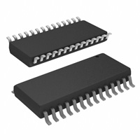
Figure 4. 28-Pin Wide Body
SOIC Package
See Package Number DW0028B
PIN DESCRIPTIONS
Pin Name
CH0 thru CH7
COM
Pin Description
Analog Inputs to the MUX (multiplexer). A channel input is selected by the address information at the DI pin, which
is loaded on the rising edge of SCLK into the address register (See Table 2, Table 3, and Table 4). The voltage
applied to these inputs should not exceed VA+ or go below VA- or below GND. Exceeding this range on an
unselected channel may corrupt the reading of a selected channel.
Analog input pin that is used as a pseudo ground when the analog multiplexer is single-ended.
MUXOUT1
MUXOUT2
Multiplexer Output pins. If the multiplexer is used, these pins should be connected to the A/DIN pins, directly or
through an amplifier and/of filter.
A/DIN1
A/DIN2
Converter Input pins. MUXOUT1 is usually tied to A/DIN1. MUXOUT2 is usually tied to A/DIN2. If external circuitry
is placed between MUXOUT1 and A/DIN1, or MUXOUT2 and A/DIN2, it may be necessary to protect these pins
against voltage overload.. The voltage at these pins should not exceed VA+ or go below AGND (see Figure 60).
DO
Data Output pin. This pin is an active push/pull output when CS is low. When CS is high, this output is TRI-STATE.
The conversion result (D0–D12) and converter status data are clocked out by the falling edge of SCLK on this pin.
The word length and format of this result can vary (see Table 1). The word length and format are controlled by the
data shifted into the multiplexer address and mode select register (see Table 5).
DI
Serial Data input pin. The data applied to this pin is shifted by the rising edge of SCLK into the multiplexer address
and mode select register. Table 2 through Table 5 show the assignment of the multiplexer address and the mode
select data.
EOC
This pin is an active push/pull output which indicates the status of the ADC12030/2/4/8. A logic low on this pin
indicates that the ADC is busy with a conversion, Auto Calibration, Auto Zero or power down cycle. The rising edge
of EOC signals the end of one of these cycles.
CONV
A logic low is required at this pin to program any mode or to change the ADC's configuration as listed in Mode
Programming Table 5. When this pin is high, the ADC is placed in the read data only mode. While in the read data
only mode, bringing CS low and pulsing SCLK will only clock out the data stored in the ADCs output shift register.
The data on DI will be neglected. A new conversion will not be started and the ADC will remain in the mode and/or
configuration previously programmed. Read data only cannot be performed while a conversion, Auto Cal or Auto
Zero are in progress.
Copyright © 1999–2013, Texas Instruments Incorporated
Submit Documentation Feedback
Product Folder Links: ADC12030 ADC12032 ADC12034 ADC12038 ADC12H030 ADC12H032 ADC12H034
ADC12H038
3
�ADC12030, ADC12032, ADC12034
ADC12038, ADC12H030, ADC12H032
ADC12H034, ADC12H038
SNAS080K – JULY 1999 – REVISED MARCH 2013
www.ti.com
PIN DESCRIPTIONS (continued)
Pin Name
Pin Description
CS
Chip Select input pin. When a logic low is applied to this pin, the rising edge of SCLK shifts the data on DI into the
address register. This low also brings DO out of TRI-STATE. With CS low the falling edge of SCLK shifts the data
resulting from the previous ADC conversion out at the DO output, with the exception of the first bit of data. When
CS is low continuously, the first bit of the data is clocked out on the rising edge of EOC (end of conversion). When
CS is toggled the falling edge of CS always clocks out the first bit of data. CS should be brought low while SCLK is
low. The falling edge of CS interrupts a conversion in progress and starts the sequence for a new conversion.
When CS is brought back low during a conversion, that conversion is prematurely terminated. The data in the
output latches may be corrupted. Therefore, when CS is brought low during a conversion in progress, the data
output at that time should be ignored. CS may also be left continuously low. In this case it is imperative that the
correct number of SCLK pulses be applied to the ADC in order to remain synchronous. After the ADC supply power
is applied the device expects to see 13 clock pulses for each I/O sequence. The number of clock pulses the ADC
expects is the same as the digital output word length. This word length can be modified by the data shifted in on the
DO pin. Table 5 details the data required.
DOR
Data Output Ready pin. This pin is an active push/pull output which is low when the conversion result is being
shifted out and goes high to signal that all the data has been shifted out.
SCLK
Serial Data Clock input. The clock applied to this input controls the rate at which the serial data exchange occurs.
The rising edge loads the information on the DI pin into the multiplexer address and mode select shift register. This
address controls which channel of the analog input multiplexer (MUX) is selected and the mode of operation for the
ADC. With CS low the falling edge of SCLK shifts the data resulting from the previous ADC conversion out on DO,
with the exception of the first bit of data. When CS is low continuously, the first bit of the data is clocked out on the
rising edge of EOC (end of conversion). When CS is toggled the falling edge of CS always clocks out the first bit of
data. CS should be brought low when SCLK is low. The rise and fall times of the clock edges should not exceed
1 µs.
CCLK
Conversion Clock input. The clock applied to this input controls the successive approximation conversion time
interval and the acquisition time. The rise and fall times of the clock edges should not exceed 1 µs.
VREF+
Positive analog voltage reference input. In order to maintain accuracy, the voltage range of VREF (VREF = VREF+ −
VREF−) is 1 VDC to 5.0 VDC and the voltage at VREF+ cannot exceed VA+. See Figure 59 for recommended
bypassing.
VREF-
The negative analog voltage reference input. In order to maintain accuracy, the voltage at this pin must not go
below GND or exceed VA+. (See Figure 59).
PD
Power Down pin. When PD is high the ADC is powered down; when PD is low the ADC is powered up, or active.
The ADC takes a maximum of 250 µs to power up after the command is given.
VA+
VD+
These are the analog and digital power supply pins. VA+ and VD+ are not connected together on the chip. These
pins should be tied to the same supply voltage and bypassed separately (see Figure 59). The operating voltage
range of VA+ and VD+ is 4.5 VDC to 5.5 VDC.
DGND
The digital ground pin (see Figure 59).
AGND
The analog ground pin (see Figure 59).
These devices have limited built-in ESD protection. The leads should be shorted together or the device placed in conductive foam
during storage or handling to prevent electrostatic damage to the MOS gates.
4
Submit Documentation Feedback
Copyright © 1999–2013, Texas Instruments Incorporated
Product Folder Links: ADC12030 ADC12032 ADC12034 ADC12038 ADC12H030 ADC12H032 ADC12H034
ADC12H038
�ADC12030, ADC12032, ADC12034
ADC12038, ADC12H030, ADC12H032
ADC12H034, ADC12H038
www.ti.com
SNAS080K – JULY 1999 – REVISED MARCH 2013
Absolute Maximum Ratings
(1) (2) (3)
Positive Supply Voltage
(V+ = VA+ = VD+)
Voltage at Inputs and Outputs
except CH0–CH7 and
COM
Voltage at Analog Inputs
CH0–CH7 and COM
6.5V
+
−0.3V to (V +0.3V)
GND −5V to (V+ +5V)
|VA+ − VD+|
300 mV
Input Current at Any Pin
Package Input Current
(4)
±30 mA
(4)
±120 mA
Package Dissipation at
TA = 25°C
(5)
500 mW
ESD Susceptibility
(6)
Human Body Model
1500V
Soldering Information
PDIP Package (10 seconds)
SOIC Package
260°C
(7)
Vapor Phase (60 seconds)
215°C
Infrared (15 seconds)
(1)
(2)
(3)
(4)
(5)
(6)
(7)
220°C
−65°C to +150°C
Storage Temperature
All voltages are measured with respect to GND, unless otherwise specified.
Absolute Maximum Ratings indicate limits beyond which damage to the device may occur. Operating Ratings indicate conditions for
which the device is functional, but do not ensure specific performance limits. For ensured specifications and test conditions, see the
Electrical Characteristics. The ensured specifications apply only for the test conditions listed. Some performance characteristics may
degrade when the device is not operated under the listed test conditions.
If Military/Aerospace specified devices are required, please contact the Texas Instruments Sales Office/ Distributors for availability and
specifications.
When the input voltage (VIN) at any pin exceeds the power supplies (VIN < GND or VIN > VA+ or VD+), the current at that pin should be
limited to 30 mA. The 120 mA maximum package input current rating limits the number of pins that can safely exceed the power
supplies with an input current of 30 mA to four.
The maximum power dissipation must be derated at elevated temperatures and is dictated by TJmax, θJA and the ambient temperature,
TA. The maximum allowable power dissipation at any temperature is PD = (TJmax − TA)/θJA or the number given in the Absolute
Maximum Ratings, whichever is lower.
The human body model is a 100 pF capacitor discharged through a 1.5 kΩ resistor into each pin.
See AN450 “Surface Mounting Methods and Their Effect on Product Reliability” or the section titled “Surface Mount” found in any post
1986 Linear Data Book for other methods of soldering surface mount devices.
Operating Ratings
(1) (2)
Operating Temperature Range
Supply Voltage (V+ = VA+ = VD+)
TMIN ≤ TA ≤ TMAX
−40°C ≤ TA ≤ +85°C
+4.5V to +5.5V
|VA+ − VD+|
≤ 100 mV
VREF+
0V to VA+
VREF−
0V to (VREF+ −1V)
VREF (VREF+ − VREF−)
VREF Common Mode Voltage Range
[(VREF+) − (VREF−)] / 2
1V to VA+
0.1 VA+ to 0.6 VA+
A/DIN1, A/DIN2, MUXOUT1 and MUXOUT2 Voltage Range
0V to VA+
IN Common Mode Voltage Range
[(VIN+) − (VIN−)] / 2
(1)
(2)
0V to VA+
Absolute Maximum Ratings indicate limits beyond which damage to the device may occur. Operating Ratings indicate conditions for
which the device is functional, but do not ensure specific performance limits. For ensured specifications and test conditions, see the
Electrical Characteristics. The ensured specifications apply only for the test conditions listed. Some performance characteristics may
degrade when the device is not operated under the listed test conditions.
All voltages are measured with respect to GND, unless otherwise specified.
Copyright © 1999–2013, Texas Instruments Incorporated
Submit Documentation Feedback
Product Folder Links: ADC12030 ADC12032 ADC12034 ADC12038 ADC12H030 ADC12H032 ADC12H034
ADC12H038
5
�ADC12030, ADC12032, ADC12034
ADC12038, ADC12H030, ADC12H032
ADC12H034, ADC12H038
SNAS080K – JULY 1999 – REVISED MARCH 2013
www.ti.com
Package Thermal Resistance
Part Number
Thermal Resistance (θJA)
ADC12(H)030CIWM
70°C/W
ADC12032CIWM
64°C/W
ADC12034CIN
42°C/W
ADC12034CIWM
57°C/W
ADC12H034CIMSA
97°C/W
ADC12(H)038CIWM
50°C/W
NOTE: Some of these devices may be obsolete or on Lifetime Buy status. Check our web site for product
availability.
Converter Electrical Characteristics
The following specifications apply for V+ = VA+ = VD+ = +5.0 VDC, VREF+ = +4.096 VDC, VREF− = 0 VDC, 12-bit + sign
conversion mode, fCK = fSK = 8 MHz for the ADC12H030, ADC12H032, ADC12H034 and ADC12H038, fCK = fSK = 5 MHz for
the ADC12030, ADC12032, ADC12034 and ADC12038, RS = 25Ω, source impedance for VREF+ and VREF− ≤ 25Ω, fullydifferential input with fixed 2.048V common-mode voltage, and 10(tCK) acquisition time unless otherwise specified. Boldface
limits apply for TA = TJ = TMIN to TMAX; all other limits TA = TJ = 25°C. (1) (2) (3)
Parameter
Test Conditions
Typical
(4)
Limits
(5)
Units
(Limits)
STATIC CONVERTER CHARACTERISTICS
Resolution with No Missing Codes
ILE
Integral Linearity Error
After Auto Cal
DNL
Differential Non-Linearity
After Auto Cal
(6) (7)
Positive Full-Scale Error
After Auto Cal
(6) (7)
Negative Full-Scale Error
After Auto Cal
(6) (7)
Offset Error
After Auto Cal (8) (7)
VIN(+) = VIN (−) = 2.048V
DC Common Mode Error
After Auto Cal
(9)
±1/2
12 + sign
Bits (min)
±1
LSB (max)
±1
LSB (max)
±1/2
±3.0
LSB (max)
±1/2
±3.0
LSB (max)
±1/2
±2
LSB (max)
±2
±3.5
LSB (max)
(1)
Two on-chip diodes are tied to each analog input through a series resistor as shown below. Input voltage magnitude up to 5V above VA+
or 5V below GND will not damage this device. However, errors in the conversion can occur (if these diodes are forward biased by more
than 50 mV) if the input voltage magnitude of selected or unselected analog input go above VA+ or below GND by more than 50 mV. As
an example, if VA+ is 4.5 VDC, full-scale input voltage must be ≤4.55 VDC to ensure accurate conversions.
(2)
To ensure accuracy, it is required that the VA+ and VD+ be connected together to the same power supply with separate bypass
capacitors at each V+ pin.
With the test condition for VREF (VREF+ − VREF−) given as +4.096V, the 12-bit LSB is 1.0 mV and the 8-bit LSB is 16.0 mV.
Typical figures are at TJ = TA = 25°C and represent most likely parametric norm.
Tested limits are specified to AOQL (Average Outgoing Quality Level).
Positive integral linearity Error is defined as the deviation of the analog value, expressed in LSBs, from the straight line that passes
through positive full-scale and zero. For Negative Integral Linearity Error, the straight line passes through negative full-scale and zero
(see Figure 6 and Figure 7).
The ADC12030 family's self-calibration technique ensures linearity and offset errors as specified, but noise inherent in the selfcalibration process will result in a maximum repeatability uncertainty of 0.2 LSB.
The human body model is a 100 pF capacitor discharged through a 1.5 kΩ resistor into each pin.
The DC common-mode error is measured in the differential multiplexer mode with the assigned positive and negative input channels
shorted together.
(3)
(4)
(5)
(6)
(7)
(8)
(9)
6
Submit Documentation Feedback
Copyright © 1999–2013, Texas Instruments Incorporated
Product Folder Links: ADC12030 ADC12032 ADC12034 ADC12038 ADC12H030 ADC12H032 ADC12H034
ADC12H038
�ADC12030, ADC12032, ADC12034
ADC12038, ADC12H030, ADC12H032
ADC12H034, ADC12H038
www.ti.com
SNAS080K – JULY 1999 – REVISED MARCH 2013
Converter Electrical Characteristics (continued)
The following specifications apply for V+ = VA+ = VD+ = +5.0 VDC, VREF+ = +4.096 VDC, VREF− = 0 VDC, 12-bit + sign
conversion mode, fCK = fSK = 8 MHz for the ADC12H030, ADC12H032, ADC12H034 and ADC12H038, fCK = fSK = 5 MHz for
the ADC12030, ADC12032, ADC12034 and ADC12038, RS = 25Ω, source impedance for VREF+ and VREF− ≤ 25Ω, fullydifferential input with fixed 2.048V common-mode voltage, and 10(tCK) acquisition time unless otherwise specified. Boldface
limits apply for TA = TJ = TMIN to TMAX; all other limits TA = TJ = 25°C. (1)(2)(3)
Parameter
TUE
Test Conditions
(6) (10) (11)
Total Unadjusted Error
After Auto Cal
Resolution with No Missing Codes
8-bit + sign mode
INL
Integral Linearity Error
8-bit + sign mode
DNL
Differential Non-Linearity
8-bit + sign mode
Positive Full-Scale Error
8-bit + sign mode
(6)
Negative Full-Scale Error
8-bit + sign mode
(6)
Offset Error
8-bit + sign mode, after Auto Zero
VIN(+) = VIN(−) = + 2.048V (10)
TUE
Total Unadjusted Error
(4)
Limits
(5)
±1
(6)
8-bit + sign mode after Auto Zero
(6) (10) (11)
Multiplexer Chan-to-Chan Matching
Power Supply Sensitivity
Typical
Units
(Limits)
LSB
8 + sign
Bits (min)
±1/2
LSB (max)
±3/4
LSB (max)
±1/2
LSB (max)
±1/2
LSB (max)
±1/2
LSB (max)
±3/4
LSB (max)
±0.05
LSB
V+ = +5V ±10%, VREF = +4.096V
Offset Error
+ Full-Scale Error
− Full-Scale Error
Integral Linearity Error
±0.5
±0.5
±0.5
±0.5
±1
±1.5
±1.5
LSB (max)
LSB (max)
LSB (max)
LSB
Output Data from “12-Bit
Conversion of Offset”
(see Table 5)
(12)
+10
−10
LSB (max)
LSB (min)
Output Data from “12-Bit
Conversion of Full-Scale”
(see Table 5)
(12)
4095
4093
LSB (max)
LSB (min)
UNIPOLAR DYNAMIC CONVERTER CHARACTERISTICS
fIN = 1 kHz, VIN = 5 VP-P, VREF+ = 5.0V
S/(N+D)
69.4
dB
Signal-to-Noise Plus Distortion Ratio fIN = 20 kHz, VIN = 5 VP-P, VREF+ = 5.0V
68.3
dB
fIN = 40 kHz, VIN = 5 VP-P, VREF+ = 5.0V
65.7
dB
VIN = 5 VP-P, where S/(N+D) drops 3 dB
31
kHz
77.0
dB
Signal-to-Noise Plus Distortion Ratio fIN = 20 kHz, VIN = ±5V, VREF = 5.0V
73.9
dB
fIN = 40 kHz, VIN = ±5V, VREF+ = 5.0V
67.0
dB
VIN = ±5V, where S/(N+D) drops 3 dB
40
kHz
−3 dB Full Power Bandwidth
DIFFERENTIAL DYNAMIC CONVERTER CHARACTERISTICS
fIN = 1 kHz, VIN = ±5V, VREF+ = 5.0V
S/(N+D)
+
−3 dB Full Power Bandwidth
REFERENCE INPUT, ANALOG INPUTS AND MULTIPLEXER CHARACTERISTICS
CREF
Reference Input Capacitance
85
pF
CA/D
A/DIN1, A/DIN2 Analog Input
Capacitance
75
pF
A/DIN1, A/DIN2 Analog Input
Leakage Current
VIN = +5.0V or VIN = 0V
±0.1
CH0–CH7 and COM Input Voltage
±1.0
µA (max)
GND − 0.05
(VA+) + 0.05
V (min)
V (max)
CCH
CH0–CH7 and COM Input
Capacitance
10
pF
CMUXOUT
MUX Output Capacitance
20
pF
(10) Offset error is a measure of the deviation from the mid-scale voltage (a code of zero), expressed in LSB. It is the worst-case value of the
code transitions between 1 to 0 and 0 to +1 (see Figure 8).
(11) Total unadjusted error includes offset, full-scale, linearity and multiplexer errors.
(12) The “12-Bit Conversion of Offset” and “12-Bit Conversion of Full-Scale” modes are intended to test the functionality of the device.
Therefore, the output data from these modes are not an indication of the accuracy of a conversion result.
Copyright © 1999–2013, Texas Instruments Incorporated
Submit Documentation Feedback
Product Folder Links: ADC12030 ADC12032 ADC12034 ADC12038 ADC12H030 ADC12H032 ADC12H034
ADC12H038
7
�ADC12030, ADC12032, ADC12034
ADC12038, ADC12H030, ADC12H032
ADC12H034, ADC12H038
SNAS080K – JULY 1999 – REVISED MARCH 2013
www.ti.com
Converter Electrical Characteristics (continued)
The following specifications apply for V+ = VA+ = VD+ = +5.0 VDC, VREF+ = +4.096 VDC, VREF− = 0 VDC, 12-bit + sign
conversion mode, fCK = fSK = 8 MHz for the ADC12H030, ADC12H032, ADC12H034 and ADC12H038, fCK = fSK = 5 MHz for
the ADC12030, ADC12032, ADC12034 and ADC12038, RS = 25Ω, source impedance for VREF+ and VREF− ≤ 25Ω, fullydifferential input with fixed 2.048V common-mode voltage, and 10(tCK) acquisition time unless otherwise specified. Boldface
limits apply for TA = TJ = TMIN to TMAX; all other limits TA = TJ = 25°C. (1)(2)(3)
Parameter
RON
Test Conditions
Typical
(4)
(5)
Limits
Units
(Limits)
Off Channel Leakage CH0–CH7
and COM Pins (13)
On Channel = 5V and Off Channel = 0V
−0.01
−0.3
µA (min)
On Channel = 0V and Off Channel = 5V
0.01
0.3
µA (max)
On Channel Leakage CH0–CH7
and COM Pins (13)
On Channel = 5V and Off Channel = 0V
0.01
0.3
µA (max)
On Channel = 0V and Off Channel = 5V
−0.01
−0.3
µA (min)
MUXOUT1 and MUXOUT2 Leakage
VMUXOUT = 5.0V or VMUXOUT = 0V
Current
0.01
0.3
µA (max)
MUX On Resistance
VIN = 2.5V and VMUXOUT = 2.4V
850
1150
Ω (max)
RON Matching Chan-to-Chan
VIN = 2.5V and VMUXOUT = 2.4V
5
%
Chan-to-Chan Crosstalk
VIN = 5 VP-P, fIN = 40 kHz
−72
dB
90
kHz
MUX Bandwidth
(13) Channel leakage current is measured after the channel selection.
DC and Logic Electrical Characteristics
The following specifications apply for V+ = VA+ = VD+ = +5.0 VDC, VREF+ = +4.096 VDC, VREF− = 0 VDC, 12-bit + sign
conversion mode, fCK = fSK = 8 MHz for the ADC12H030, ADC12H032, ADC12H034 and ADC12H038, fCK = fSK = 5 MHz for
the ADC12030, ADC12032, ADC12034 and ADC12038, RS = 25Ω, source impedance for VREF+ and VREF− ≤ 25Ω, fullydifferential input with fixed 2.048V common-mode voltage, and 10(tCK) acquisition time unless otherwise specified. Boldface
limits apply for TA = TJ = TMIN to TMAX; all other limits TA = TJ = 25°C. (1) (2) (3)
Parameter
Test Conditions
Typical
(4)
Limits
(5)
Units
(Limits)
CCLK, CS, CONV, DI, PD AND SCLK INPUT CHARACTERISTICS
VIN(1)
Logical “1” Input Voltage
V+ = 5.5V
2.0
V (min)
VIN(0)
Logical “0” Input Voltage
V+ = 4.5V
0.8
V (max)
IIN(1)
Logical “1” Input Current
VIN = 5.0V
0.005
1.0
µA (max)
IIN(0)
Logical “0” Input Current
VIN = 0V
−0.005
−1.0
µA (min)
V+ = 4.5V, IOUT = −360 µA
2.4
V (min)
V+ = 4.5V, IOUT = − 10 µA
4.25
V (min)
DO, EOC AND DOR DIGITAL OUTPUT CHARACTERISTICS
VOUT(1)
Logical “1” Output Voltage
(1)
Two on-chip diodes are tied to each analog input through a series resistor as shown below. Input voltage magnitude up to 5V above VA+
or 5V below GND will not damage this device. However, errors in the conversion can occur (if these diodes are forward biased by more
than 50 mV) if the input voltage magnitude of selected or unselected analog input go above VA+ or below GND by more than 50 mV. As
an example, if VA+ is 4.5 VDC, full-scale input voltage must be ≤4.55 VDC to ensure accurate conversions.
(2)
To ensure accuracy, it is required that the VA+ and VD+ be connected together to the same power supply with separate bypass
capacitors at each V+ pin.
With the test condition for VREF (VREF+ − VREF−) given as +4.096V, the 12-bit LSB is 1.0 mV and the 8-bit LSB is 16.0 mV.
Typical figures are at TJ = TA = 25°C and represent most likely parametric norm.
Tested limits are specified to AOQL (Average Outgoing Quality Level).
(3)
(4)
(5)
8
Submit Documentation Feedback
Copyright © 1999–2013, Texas Instruments Incorporated
Product Folder Links: ADC12030 ADC12032 ADC12034 ADC12038 ADC12H030 ADC12H032 ADC12H034
ADC12H038
�ADC12030, ADC12032, ADC12034
ADC12038, ADC12H030, ADC12H032
ADC12H034, ADC12H038
www.ti.com
SNAS080K – JULY 1999 – REVISED MARCH 2013
DC and Logic Electrical Characteristics (continued)
The following specifications apply for V+ = VA+ = VD+ = +5.0 VDC, VREF+ = +4.096 VDC, VREF− = 0 VDC, 12-bit + sign
conversion mode, fCK = fSK = 8 MHz for the ADC12H030, ADC12H032, ADC12H034 and ADC12H038, fCK = fSK = 5 MHz for
the ADC12030, ADC12032, ADC12034 and ADC12038, RS = 25Ω, source impedance for VREF+ and VREF− ≤ 25Ω, fullydifferential input with fixed 2.048V common-mode voltage, and 10(tCK) acquisition time unless otherwise specified. Boldface
limits apply for TA = TJ = TMIN to TMAX; all other limits TA = TJ = 25°C. (1)(2)(3)
Parameter
VOUT(0)
Test Conditions
Typical
(4)
Limits
V+ = 4.5V, IOUT = 1.6 mA
Logical “0” Output Voltage
(5)
Units
(Limits)
0.4
V (max)
VOUT = 0V
−0.1
−3.0
µA (max)
VOUT = 5V
0.1
3.0
µA (max)
IOUT
TRI-STATE Output Current
+ISC
Output Short Circuit Source Current
VOUT = 0V
14
6.5
mA (min)
−ISC
Output Short Circuit Sink Current
VOUT = VD+
16
8.0
mA (min)
Digital Supply Current
ADC12030, ADC12032, ADC12034 and
ADC12038
Awake
CS = HIGH, Powered Down, CCLK on
CS = HIGH, Powered Down, CCLK off
1.6
600
20
2.5
mA (max)
µA
µA
Digital Supply Current
ADC12H030, ADC12H032, ADC12H034
and ADC12H038
Awake
CS = HIGH, Powered Down, CCLK on
CS = HIGH, Powered Down, CCLK off
2.3
0.9
20
3.2
mA
mA
µA
Positive Analog Supply Current
Awake
CS = HIGH, Powered Down, CCLK on
CS = HIGH, Powered Down, CCLK off
2.7
10
0.1
4.0
IA+
mA (max)
µA
µA
IREF
Reference Input Current
Awake
CS = HIGH, Powered Down
70
0.1
POWER SUPPLY CHARACTERISTICS
ID+
µA
µA
AC Electrical Characteristics
The following specifications apply for V+ = VA+ = VD+ = +5.0 VDC, VREF+ = +4.096 VDC, VREF− = 0 VDC, 12-bit + sign
conversion mode, tr = tf = 3 ns, fCK = fSK = 8 MHz for the ADC12H030, ADC12H032, ADC12H034 and ADC12H038, fCK = fSK
= 5 MHz for the ADC12030, ADC12032, ADC12034 and ADC12038, RS = 25Ω, source impedance for VREF+ and VREF− ≤
25Ω, fully-differential input with fixed 2.048V common-mode voltage, and 10(tCK) acquisition time unless otherwise specified.
Boldface limits apply for TA = TJ = TMIN to TMAX; all other limits TA = TJ = 25°C. (1)
Typical
ADC12H030/2/4/8
Limits (3)
ADC12030/2/4/8
Limits (3)
Units
(Limits)
Conversion Clock (CCLK)
Frequency
10
1
8
5
MHz (max)
MHz (min)
Serial Data Clock SCLK Frequency
10
0
8
5
MHz (max)
Hz (min)
Conversion Clock Duty Cycle
40
60
40
60
% (min)
% (max)
Serial Data Clock Duty Cycle
40
60
40
60
% (min)
% (max)
Parameter
fCK
fSK
tC
(1)
(2)
(3)
Conversion Time
Test Conditions
(2)
12-Bit + Sign or 12Bit
44(tCK)
44(tCK)
5.5
44(tCK)
8.8
(max)
µs (max)
8-Bit + Sign or 8-Bit
21(tCK)
21(tCK)
2.625
21(tCK)
4.2
(max)
µs (max)
Timing specifications are tested at the TTL logic levels, VIL = 0.4V for a falling edge and VIH = 2.4V for a rising edge. TRI-STATE output
voltage is forced to 1.4V.
Typical figures are at TJ = TA = 25°C and represent most likely parametric norm.
Tested limits are specified to AOQL (Average Outgoing Quality Level).
Copyright © 1999–2013, Texas Instruments Incorporated
Submit Documentation Feedback
Product Folder Links: ADC12030 ADC12032 ADC12034 ADC12038 ADC12H030 ADC12H032 ADC12H034
ADC12H038
9
�ADC12030, ADC12032, ADC12034
ADC12038, ADC12H030, ADC12H032
ADC12H034, ADC12H038
SNAS080K – JULY 1999 – REVISED MARCH 2013
www.ti.com
AC Electrical Characteristics (continued)
The following specifications apply for V+ = VA+ = VD+ = +5.0 VDC, VREF+ = +4.096 VDC, VREF− = 0 VDC, 12-bit + sign
conversion mode, tr = tf = 3 ns, fCK = fSK = 8 MHz for the ADC12H030, ADC12H032, ADC12H034 and ADC12H038, fCK = fSK
= 5 MHz for the ADC12030, ADC12032, ADC12034 and ADC12038, RS = 25Ω, source impedance for VREF+ and VREF− ≤
25Ω, fully-differential input with fixed 2.048V common-mode voltage, and 10(tCK) acquisition time unless otherwise specified.
Boldface limits apply for TA = TJ = TMIN to TMAX; all other limits TA = TJ = 25°C. (1)
Parameter
Test Conditions
Typical
(2)
6(tCK)
6 Cycles
Programmed
10(tCK)
10 Cycles
Programmed
tA
Acquisition Time
(4)
18(tCK)
18 Cycles
Programmed
tAZ
Auto Zero Time
Self-Calibration or Auto Zero
Synchronization Time from DOR
tDOR
DOR High Time when CS is Low
Continuously for Read Data and
Software Power Up/Down
tCONV
CONV Valid Data Time
(4)
10
6(tCK)
6(tCK)
(min)
7(tCK)
7(tCK)
(max)
0.75
1.2
µs (min)
µs (max)
0.875
1.4
10(tCK)
10(tCK)
(min)
11(tCK)
11(tCK)
(max)
1.25
2.0
µs (min)
1.375
2.2
µs (max)
18(tCK)
18(tCK)
(min)
19(tCK)
19(tCK)
(max)
3.6
µs (min)
3.8
µs (max)
34(tCK)
34(tCK)
(min)
35(tCK)
35(tCK)
(max)
4.25
6.8
µs (min)
4.375
7.0
µs (max)
4944(tCK)
4944(tCK)
(max)
618.0
988.8
µs (max)
76(tCK)
76(tCK)
(max)
9.5
15.2
µs (max)
2(tCK)
2(tCK)
(min)
3(tCK)
3(tCK)
(max)
0.250
0.40
µs (min)
0.375
0.60
µs (max)
9(tSK)
9(tSK)
1.125
9(tSK)
1.8
(max)
µs (max)
8(tSK)
8(tSK)
8(tSK)
(max)
1.0
1.6
µs (max)
4944(tCK)
76(tCK)
2(tCK)
tSYNC
Units
(Limits)
2.25
34 Cycles
Programmed
Self-Calibration Time
ADC12030/2/4/8
Limits (3)
2.375
34(tCK)
tCKAL
ADC12H030/2/4/8
Limits (3)
If SCLK and CCLK are driven from the same clock source, then tA is 6, 10, 18 or 34 clock periods minimum and maximum.
Submit Documentation Feedback
Copyright © 1999–2013, Texas Instruments Incorporated
Product Folder Links: ADC12030 ADC12032 ADC12034 ADC12038 ADC12H030 ADC12H032 ADC12H034
ADC12H038
�ADC12030, ADC12032, ADC12034
ADC12038, ADC12H030, ADC12H032
ADC12H034, ADC12H038
www.ti.com
SNAS080K – JULY 1999 – REVISED MARCH 2013
Timing Characteristics
The following specifications apply for V+ = VA+ = VD+ = +5.0 VDC, VREF+ = +4.096 VDC, VREF− = 0 VDC, 12-bit + sign
conversion mode, tr = tf = 3 ns, fCK = fSK = 8 MHz for the ADC12H030, ADC12H032, ADC12H034 and ADC12H03, fCK = fSK =
5 MHz for the ADC12030, ADC12032, ADC12034 and ADC12038, RS = 25Ω, source impedance for VREF+ and VREF− ≤ 25Ω,
fully-differential input with fixed 2.048V common-mode voltage, and 10(tCK) acquisition time unless otherwise specified.
Boldface limits apply for TA = TJ = TMIN to TMAX; all other limits TA = TJ = 25°C. (1)
Parameter
Test Conditions
Typical
Limits
(3)
Units
(Limits)
(2)
tHPU
Hardware Power-Up Time, Time from PD Falling Edge to
EOC Rising Edge
140
250
µs (max)
tSPU
Software Power-Up Time, Time from Serial Data Clock
Falling Edge to EOC Rising Edge
140
250
µs (max)
tACC
Access Time Delay from CS Falling Edge to DO Data Valid
20
50
ns (max)
tSET-UP
Set-Up Time of CS Falling Edge to Serial Data Clock Rising
Edge
30
ns (min)
tDELAY
Delay from SCLK Falling Edge to CS Falling Edge
t1H, t0H
Delay from CS Rising Edge to DO TRI-STATE
tHDI
tSDI
0
5
ns (min)
40
100
ns (max)
DI Hold Time from Serial Data Clock Rising Edge
5
15
ns (min)
DI Set-Up Time from Serial Data Clock Rising Edge
5
10
ns (min)
25
50
5
ns (max)
ns (min)
35
50
ns (max)
tHDO
DO Hold Time from Serial Data Clock Falling Edge
tDDO
Delay from Serial Data Clock Falling Edge to DO Data Valid
tRDO
tFDO
RL = 3k, CL = 100 pF
RL = 3k, CL = 100 pF
DO Rise Time, TRI-STATE to High
RL = 3k, CL = 100 pF
10
30
ns (max)
DO Rise Time, Low to High
RL = 3k, CL = 100 pF
10
30
ns (max)
DO Fall Time, TRI-STATE to Low
RL = 3k, CL = 100 pF
12
30
ns (max)
DO Fall Time, High to Low
RL = 3k, CL = 100 pF
12
30
ns (max)
tCD
Delay from CS Falling Edge to DOR Falling Edge
25
45
ns (max)
tSD
Delay from Serial Data Clock Falling Edge to DOR Rising
Edge
25
45
ns (max)
CIN
Capacitance of Logic Inputs
10
pF
COUT
Capacitance of Logic Outputs
20
pF
(1)
(2)
(3)
Timing specifications are tested at the TTL logic levels, VIL = 0.4V for a falling edge and VIH = 2.4V for a rising edge. TRI-STATE output
voltage is forced to 1.4V.
Typical figures are at TJ = TA = 25°C and represent most likely parametric norm.
Tested limits are specified to AOQL (Average Outgoing Quality Level).
Copyright © 1999–2013, Texas Instruments Incorporated
Submit Documentation Feedback
Product Folder Links: ADC12030 ADC12032 ADC12034 ADC12038 ADC12H030 ADC12H032 ADC12H034
ADC12H038
11
�ADC12030, ADC12032, ADC12034
ADC12038, ADC12H030, ADC12H032
ADC12H034, ADC12H038
SNAS080K – JULY 1999 – REVISED MARCH 2013
www.ti.com
Figure 5. Transfer Characteristic
Figure 6. Simplified Error Curve vs. Output Code without Auto Calibration or Auto Zero Cycles
12
Submit Documentation Feedback
Copyright © 1999–2013, Texas Instruments Incorporated
Product Folder Links: ADC12030 ADC12032 ADC12034 ADC12038 ADC12H030 ADC12H032 ADC12H034
ADC12H038
�ADC12030, ADC12032, ADC12034
ADC12038, ADC12H030, ADC12H032
ADC12H034, ADC12H038
www.ti.com
SNAS080K – JULY 1999 – REVISED MARCH 2013
Figure 7. Simplified Error Curve vs. Output Code after Auto Calibration Cycle
Figure 8. Offset or Zero Error Voltage
Copyright © 1999–2013, Texas Instruments Incorporated
Submit Documentation Feedback
Product Folder Links: ADC12030 ADC12032 ADC12034 ADC12038 ADC12H030 ADC12H032 ADC12H034
ADC12H038
13
�ADC12030, ADC12032, ADC12034
ADC12038, ADC12H030, ADC12H032
ADC12H034, ADC12H038
SNAS080K – JULY 1999 – REVISED MARCH 2013
www.ti.com
Typical Performance Characteristics
(1)
The following curves apply for 12-bit + sign mode after Auto Calibration unless otherwise specified. The performance for 8-bit
+ sign mode is equal to or better than shown.
(1)
14
Linearity Error Change
vs. Clock Frequency
Linearity Error Change
vs. Temperature
Figure 9.
Figure 10.
Linearity Error Change
vs. Reference Voltage
Linearity Error Change
vs. Supply Voltage
Figure 11.
Figure 12.
Full-Scale Error Change
vs. Clock Frequency
Full-Scale Error Change
vs. Temperature
Figure 13.
Figure 14.
With the test condition for VREF (VREF+ − VREF−) given as +4.096V, the 12-bit LSB is 1.0 mV and the 8-bit LSB is 16.0 mV.
Submit Documentation Feedback
Copyright © 1999–2013, Texas Instruments Incorporated
Product Folder Links: ADC12030 ADC12032 ADC12034 ADC12038 ADC12H030 ADC12H032 ADC12H034
ADC12H038
�ADC12030, ADC12032, ADC12034
ADC12038, ADC12H030, ADC12H032
ADC12H034, ADC12H038
www.ti.com
SNAS080K – JULY 1999 – REVISED MARCH 2013
Typical Performance Characteristics (1) (continued)
The following curves apply for 12-bit + sign mode after Auto Calibration unless otherwise specified. The performance for 8-bit
+ sign mode is equal to or better than shown.
Full-Scale Error Change
vs. Reference Voltage
Full-Scale Error Change
vs. Supply Voltage
Figure 15.
Figure 16.
Offset or Zero Error Change
vs. Clock Frequency
Offset or Zero Error Change
vs. Temperature
Figure 17.
Figure 18.
Offset or Zero Error Change
vs. Reference Voltage
Offset or Zero Error Change
vs. Supply Voltage
Figure 19.
Figure 20.
Copyright © 1999–2013, Texas Instruments Incorporated
Submit Documentation Feedback
Product Folder Links: ADC12030 ADC12032 ADC12034 ADC12038 ADC12H030 ADC12H032 ADC12H034
ADC12H038
15
�ADC12030, ADC12032, ADC12034
ADC12038, ADC12H030, ADC12H032
ADC12H034, ADC12H038
SNAS080K – JULY 1999 – REVISED MARCH 2013
www.ti.com
Typical Performance Characteristics (1) (continued)
The following curves apply for 12-bit + sign mode after Auto Calibration unless otherwise specified. The performance for 8-bit
+ sign mode is equal to or better than shown.
Analog Supply Current
vs. Temperature
Digital Supply Current
vs. Clock Frequency
Figure 21.
Figure 22.
Digital Supply Current
vs. Temperature
Figure 23.
16
Submit Documentation Feedback
Copyright © 1999–2013, Texas Instruments Incorporated
Product Folder Links: ADC12030 ADC12032 ADC12034 ADC12038 ADC12H030 ADC12H032 ADC12H034
ADC12H038
�ADC12030, ADC12032, ADC12034
ADC12038, ADC12H030, ADC12H032
ADC12H034, ADC12H038
www.ti.com
SNAS080K – JULY 1999 – REVISED MARCH 2013
Typical Dynamic Performance Characteristics
The following curves apply for 12-bit + sign mode after Auto Calibration unless otherwise specified.
Bipolar Spectral Response
with 1 kHz Sine Wave Input
Bipolar Spectral Response
with 10 kHz Sine Wave Input
Figure 24.
Figure 25.
Bipolar Spectral Response
with 20 kHz Sine Wave Input
Bipolar Spectral Response
with 30 kHz Sine Wave Input
Figure 26.
Figure 27.
Bipolar Spectral Response
with 40 kHz Sine Wave Input
Bipolar Spectral Response
with 50 kHz Sine Wave Input
Figure 28.
Figure 29.
Copyright © 1999–2013, Texas Instruments Incorporated
Submit Documentation Feedback
Product Folder Links: ADC12030 ADC12032 ADC12034 ADC12038 ADC12H030 ADC12H032 ADC12H034
ADC12H038
17
�ADC12030, ADC12032, ADC12034
ADC12038, ADC12H030, ADC12H032
ADC12H034, ADC12H038
SNAS080K – JULY 1999 – REVISED MARCH 2013
www.ti.com
Typical Dynamic Performance Characteristics (continued)
The following curves apply for 12-bit + sign mode after Auto Calibration unless otherwise specified.
18
Bipolar Spurious Free
Dynamic Range
Unipolar Signal-to-Noise Ratio
vs. Input Frequency
Figure 30.
Figure 31.
Unipolar Signal-to-Noise
+ Distortion Ratio
vs. Input Frequency
Unipolar Signal-to-Noise
+ Distortion Ratio
vs. Input Signal Level
Figure 32.
Figure 33.
Unipolar Spectral Response
with 1 kHz Sine Wave Input
Unipolar Spectral Response
with 10 kHz Sine Wave Input
Figure 34.
Figure 35.
Submit Documentation Feedback
Copyright © 1999–2013, Texas Instruments Incorporated
Product Folder Links: ADC12030 ADC12032 ADC12034 ADC12038 ADC12H030 ADC12H032 ADC12H034
ADC12H038
�ADC12030, ADC12032, ADC12034
ADC12038, ADC12H030, ADC12H032
ADC12H034, ADC12H038
www.ti.com
SNAS080K – JULY 1999 – REVISED MARCH 2013
Typical Dynamic Performance Characteristics (continued)
The following curves apply for 12-bit + sign mode after Auto Calibration unless otherwise specified.
Unipolar Spectral Response
with 20 kHz Sine Wave Input
Unipolar Spectral Response
with 30 kHz Sine Wave Input
Figure 36.
Figure 37.
Unipolar Spectral Response
with 40 kHz Sine Wave Input
Unipolar Spectral Response
with 50 kHz Sine Wave Input
Figure 38.
Figure 39.
Copyright © 1999–2013, Texas Instruments Incorporated
Submit Documentation Feedback
Product Folder Links: ADC12030 ADC12032 ADC12034 ADC12038 ADC12H030 ADC12H032 ADC12H034
ADC12H038
19
�ADC12030, ADC12032, ADC12034
ADC12038, ADC12H030, ADC12H032
ADC12H034, ADC12H038
SNAS080K – JULY 1999 – REVISED MARCH 2013
www.ti.com
Test Circuits
Figure 40. DO “TRI-STATE” (t1H, tOH)
Figure 41. DO except “TRI-STATE”
Figure 42. Leakage Current
Timing Diagrams
Figure 43. DO Falling and Rising Edge
Figure 44. DO “TRI-STATE” Falling and Rising Edge
20
Submit Documentation Feedback
Copyright © 1999–2013, Texas Instruments Incorporated
Product Folder Links: ADC12030 ADC12032 ADC12034 ADC12038 ADC12H030 ADC12H032 ADC12H034
ADC12H038
�ADC12030, ADC12032, ADC12034
ADC12038, ADC12H030, ADC12H032
ADC12H034, ADC12H038
www.ti.com
SNAS080K – JULY 1999 – REVISED MARCH 2013
Figure 45. DI Data Input Timing
Figure 46. DO Data Output Timing Using CS
0
1
2
3
4
n
SCLK
tSET-UP
CS
tDDO
tHDO
tHDO
tACC
DO
2.4V
2.4V
0.4V
tDDO
0.4V
2.4V
tSD
tCD
DOR
EOC
Figure 47. DO Data Output Timing with CS Continuously Low
Copyright © 1999–2013, Texas Instruments Incorporated
Submit Documentation Feedback
Product Folder Links: ADC12030 ADC12032 ADC12034 ADC12038 ADC12H030 ADC12H032 ADC12H034
ADC12H038
21
�ADC12030, ADC12032, ADC12034
ADC12038, ADC12H030, ADC12H032
ADC12H034, ADC12H038
SNAS080K – JULY 1999 – REVISED MARCH 2013
www.ti.com
Note: DO output data is not valid during this cycle.
Figure 48. ADC12038 Auto Cal or Auto Zero
Figure 49. ADC12038 Read Data without Starting a Conversion Using CS
22
Submit Documentation Feedback
Copyright © 1999–2013, Texas Instruments Incorporated
Product Folder Links: ADC12030 ADC12032 ADC12034 ADC12038 ADC12H030 ADC12H032 ADC12H034
ADC12H038
�ADC12030, ADC12032, ADC12034
ADC12038, ADC12H030, ADC12H032
ADC12H034, ADC12H038
www.ti.com
SNAS080K – JULY 1999 – REVISED MARCH 2013
Figure 50. ADC12038 Read Data without Starting a Conversion with CS Continuously Low
Figure 51. ADC12038 Conversion Using CS with 8-Bit Digital Output Format
Copyright © 1999–2013, Texas Instruments Incorporated
Submit Documentation Feedback
Product Folder Links: ADC12030 ADC12032 ADC12034 ADC12038 ADC12H030 ADC12H032 ADC12H034
ADC12H038
23
�ADC12030, ADC12032, ADC12034
ADC12038, ADC12H030, ADC12H032
ADC12H034, ADC12H038
SNAS080K – JULY 1999 – REVISED MARCH 2013
www.ti.com
Figure 52. ADC12038 Conversion Using CS with 16-Bit Digital Output Format
Figure 53. ADC12038 Conversion with CS Continuously Low and 8-Bit Digital Output Format
24
Submit Documentation Feedback
Copyright © 1999–2013, Texas Instruments Incorporated
Product Folder Links: ADC12030 ADC12032 ADC12034 ADC12038 ADC12H030 ADC12H032 ADC12H034
ADC12H038
�ADC12030, ADC12032, ADC12034
ADC12038, ADC12H030, ADC12H032
ADC12H034, ADC12H038
www.ti.com
SNAS080K – JULY 1999 – REVISED MARCH 2013
Figure 54. ADC12038 Conversion with CS Continuously Low and 16-Bit Digital Output Format
Figure 55. ADC12038 Software Power Up/Down Using CS with 16-Bit Digital Output Format
Copyright © 1999–2013, Texas Instruments Incorporated
Submit Documentation Feedback
Product Folder Links: ADC12030 ADC12032 ADC12034 ADC12038 ADC12H030 ADC12H032 ADC12H034
ADC12H038
25
�ADC12030, ADC12032, ADC12034
ADC12038, ADC12H030, ADC12H032
ADC12H034, ADC12H038
SNAS080K – JULY 1999 – REVISED MARCH 2013
www.ti.com
Figure 56. ADC12038 Software Power Up/Down with CS Continuously Low and 16-Bit Digital Output
Format
Note: Hardware power up/down may occur at any time. If PD is high while a conversion is in progress that conversion
will be corrupted and erroneous data will be stored in the output shift register.
Figure 57. ADC12038 Hardware Power Up/Down
26
Submit Documentation Feedback
Copyright © 1999–2013, Texas Instruments Incorporated
Product Folder Links: ADC12030 ADC12032 ADC12034 ADC12038 ADC12H030 ADC12H032 ADC12H034
ADC12H038
�ADC12030, ADC12032, ADC12034
ADC12038, ADC12H030, ADC12H032
ADC12H034, ADC12H038
www.ti.com
SNAS080K – JULY 1999 – REVISED MARCH 2013
Note: In order for all 9 bits of Status Information to be accessible, the last conversion programmed before Cycle N
needs to have a resolution of 8 bits plus sign, 12 bits, 12 bits plus sign, or greater.
Figure 58. ADC12038 Configuration Modification—Example of a Status Read
VA+
ANALOG
INPUT
VOLTAGE
ASSIGNED
(+) INPUT
VD+
**
0.01 uF
**
0.1 uF
10 uF *
**
0.01 uF
**
0.1 uF
10 uF *
**
0.01 uF
**
0.1 uF
10 uF *
+5.0V
ADC
ANALOG
INPUT
VOLTAGE
ASSIGNED
(-) INPUT
VREF+
+4.096V
VREFAGND
DGND
ANALOG INPUT VOLTAGE
GROUND REFERENCE
*Tantalum
**Monolithic Ceramic or better
Figure 59. Recommended Power Supply Bypassing and Grounding
Figure 60. Protecting the MUXOUT1, MUXOUT2, A/DIN1 and A/DIN2 Analog Pins
Copyright © 1999–2013, Texas Instruments Incorporated
Submit Documentation Feedback
Product Folder Links: ADC12030 ADC12032 ADC12034 ADC12038 ADC12H030 ADC12H032 ADC12H034
ADC12H038
27
�ADC12030, ADC12032, ADC12034
ADC12038, ADC12H030, ADC12H032
ADC12H034, ADC12H038
SNAS080K – JULY 1999 – REVISED MARCH 2013
www.ti.com
Format and Set-Up Tables
Table 1. Data Out Formats (1)
DO Formats
MSB
First
DB0
DB1
DB2
DB3
DB4
DB5
DB6
DB7
DB8
DB9
DB10
DB11
DB12
DB13
DB14
DB15
DB16
17
Bits
X
X
X
X
Sign
MSB
10
9
8
7
6
5
4
3
2
1
LSB
13
Bits
Sign
MSB
10
9
8
7
6
5
4
3
2
1
LSB
9
Bits
Sign
MSB
6
5
4
3
2
1
LSB
17
Bits
LSB
1
2
3
4
5
6
7
8
9
10
MSB
Sign
X
X
X
X
13
Bits
LSB
1
2
3
4
5
6
7
8
9
10
MSB
Sign
9
Bits
LSB
1
2
3
4
5
6
MSB
Sign
16
Bits
0
0
0
0
MSB
10
9
8
7
6
5
4
3
2
1
LSB
12
Bits
MSB
10
9
8
7
6
5
4
3
2
1
LSB
8
Bits
MSB
6
5
4
3
2
1
LSB
16
Bits
LSB
1
2
3
4
5
6
7
8
9
10
MSB
0
0
0
12
Bits
LSB
1
2
3
4
5
6
7
8
9
10
MSB
8
Bits
LSB
1
2
3
4
5
6
MSB
with Sign
LSB
First
MSB
First
without
sign
LSB
First
(1)
X = High or Low state.
Table 2. ADC12038 Multiplexer Addressing
Analog Channel Addressed
and Assignment
with A/DIN1 tied to MUXOUT1
and A/DIN2 tied to MUXOUT2
MUX Address
DI0
DI1
DI2
DI3
CH0
CH1
L
L
L
L
+
−
L
L
L
H
L
L
H
L
L
L
H
H
L
H
L
L
L
H
L
H
L
H
H
L
L
H
H
H
H
L
L
L
H
L
L
H
H
L
H
L
H
L
H
H
H
H
L
L
H
H
L
H
H
H
H
L
H
H
H
H
28
CH2
+
CH3
CH4
CH5
ADC Input Polarity
Assignment
CH6
COM
A/DIN1
A/DIN2
MUXOUT1
MUXOUT2
+
−
CH0
CH1
+
−
CH2
CH3
+
−
CH4
CH5
+
−
CH6
CH7
−
+
CH0
CH1
−
+
CH2
CH3
−
+
CH4
CH5
−
+
CH6
CH7
−
+
−
CH0
COM
−
+
−
CH2
COM
−
+
−
CH4
COM
−
+
−
CH6
COM
−
+
−
CH1
COM
−
+
−
CH3
COM
−
+
−
CH5
COM
−
+
−
CH7
COM
−
+
−
+
−
CH7
−
+
−
+
−
+
−
+
+
+
+
+
+
Submit Documentation Feedback
+
+
+
Multiplexer Output
Channel Assignment
Mode
Differential
Single-Ended
Copyright © 1999–2013, Texas Instruments Incorporated
Product Folder Links: ADC12030 ADC12032 ADC12034 ADC12038 ADC12H030 ADC12H032 ADC12H034
ADC12H038
�ADC12030, ADC12032, ADC12034
ADC12038, ADC12H030, ADC12H032
ADC12H034, ADC12H038
www.ti.com
SNAS080K – JULY 1999 – REVISED MARCH 2013
Table 3. ADC12034 Multiplexer Addressing
Analog Channel Addressed
and Assignment
with A/DIN1 tied to MUXOUT1
and A/DIN2 tied to MUXOUT2
MUX Address
DI0
DI1
DI2
CH0
CH1
L
L
L
+
−
L
L
H
L
H
L
−
+
L
H
H
H
L
L
H
L
H
H
H
L
H
H
H
CH2
CH3
ADC Input Polarity
Assignment
COM
A/DIN1
A/DIN2
MUXOUT1
MUXOUT2
+
−
CH0
CH1
+
−
CH2
CH3
−
+
CH0
CH1
−
+
−
−
+
CH2
CH3
−
+
−
CH0
COM
−
+
−
CH2
COM
−
+
−
CH1
COM
−
+
−
CH3
COM
+
+
+
+
+
Multiplexer Output Channel
Assignment
Mode
Differential
Single-Ended
Table 4. ADC12032 and ADC12030 Multiplexer Addressing
Analog Channel Addressed
and Assignment
with A/DIN1 tied to MUXOUT1
and A/DIN2 tied to MUXOUT2
MUX Address
ADC Input Polarity
Assignment
COM
Multiplexer Output
Channel Assignment
Mode
DI0
DI1
CH0
CH1
A/DIN1
A/DIN2
MUXOUT1
MUXOUT2
L
L
+
−
+
−
CH0
CH1
L
H
−
+
−
+
CH0
CH1
H
L
+
−
+
−
CH0
COM
H
H
−
+
−
CH1
COM
+
Differential
Single-Ended
NOTE
ADC12030 and ADC12H030 do not have A/DIN1, A/DIN2, MUXOUT1 and MUXOUT2
pins.
Table 5. Mode Programming (1)
ADC12038
DI0
DI1
DI2
ADC12034
DI0
DI1
DI2
ADC12030
and
ADC12032
DI0
DI4
DI5
DI6
DI7
DI3
DI4
DI5
DI6
DI1
DI2
DI3
DI4
DI5
See Table 2, Table 3, or
Table 4
L
L
L
See Table 2, Table 3, or
Table 4
L
L
See Table 2, Table 3, or
Table 4
L
L
L
L
DI3
L
See Table 2, Table 3, or
Table 4
See Table 2, Table 3, or
Table 4
See Table 2, Table 3, or
Table 4
(1)
Mode Selected
(Current)
DO Format
(next Conversion
Cycle)
L
12 Bit Conversion
12 or 13 Bit MSB First
L
H
12 Bit Conversion
16 or 17 Bit MSB First
L
H
L
8 Bit Conversion
8 or 9 Bit MSB First
L
L
H
H
12 Bit Conversion of Full-Scale
12 or 13 Bit MSB First
L
H
L
L
12 Bit Conversion
12 or 13 Bit LSB First
L
H
L
H
12 Bit Conversion
16 or 17 Bit LSB First
L
H
H
L
8 Bit Conversion
8 or 9 Bit LSB First
The ADC powers up with no Auto Cal, no Auto Zero, 10 CCLK acquisition time, 12-bit + sign conversion, power up, 12- or 13-bit MSB
first, and user mode.
X = Don't Care
Copyright © 1999–2013, Texas Instruments Incorporated
Submit Documentation Feedback
Product Folder Links: ADC12030 ADC12032 ADC12034 ADC12038 ADC12H030 ADC12H032 ADC12H034
ADC12H038
29
�ADC12030, ADC12032, ADC12034
ADC12038, ADC12H030, ADC12H032
ADC12H034, ADC12H038
SNAS080K – JULY 1999 – REVISED MARCH 2013
www.ti.com
Table 5. Mode Programming(1) (continued)
ADC12038
DI0
DI1
DI2
ADC12034
DI0
DI1
DI2
ADC12030
and
ADC12032
DI0
DI1
L
L
L
L
L
L
L
L
L
DI3
DI4
DI5
DI6
DI7
DI3
DI4
DI5
DI6
DI2
DI3
DI4
DI5
L
L
H
H
L
H
L
L
L
L
H
L
L
L
L
H
L
L
L
L
L
L
L
L
L
L
L
H
L
L
L
L
Mode Selected
(Current)
DO Format
(next Conversion
Cycle)
H
12 Bit Conversion of Offset
12 or 13 Bit LSB First
L
Auto Cal
No Change
L
H
Auto Zero
No Change
L
H
L
Power Up
No Change
H
L
H
H
Power Down
No Change
H
H
L
L
Read Status Register
No Change
L
H
H
L
H
Data Out without Sign
No Change
L
L
H
H
L
H
Data Out with Sign
No Change
L
L
H
H
H
L
Acquisition Time—6 CCLK Cycles
No Change
H
L
L
H
H
H
L
Acquisition Time—10 CCLK Cycles
No Change
H
L
L
L
H
H
H
L
Acquisition Time—18 CCLK Cycles
No Change
H
H
L
L
H
H
H
L
Acquisition Time—34 CCLK Cycles
No Change
L
L
L
L
H
H
H
H
User Mode
No Change
H
Test Mode
(CH1–CH7 become Active Outputs)
No Change
H
X
X
X
H
H
H
Table 6. Conversion/Read Data Only Mode Programming
CS
CONV
PD
Mode
L
L
L
See Table 5 for Mode
L
H
L
Read Only (Previous DO Format). No Conversion.
H
X
L
Idle
X
X
H
Power Down
Table 7. Status Register
Status Bit
Location
DB0
DB1
DB2
DB3
DB4
DB5
DB6
DB7
DB8
Status Bit
PU
PD
Cal
8 or 9
12 or 13
16 or 17
Sign
Justification
Test Mode
“High”
indicates an
Auto Cal
Sequence
is in
progress
“High”
indicates an
8 or 9 bit
format
“High”
indicates a
12 or 13 bit
format
“High”
indicates a
16 or 17 bit
format
Device Status
Function
30
“High”
indicates a
Power Up
Sequence
is in
progress
“High”
indicates a
Power
Down
Sequence
is in
progress
Submit Documentation Feedback
DO Output Format Status
“High”
indicates
that the
sign bit is
included.
When “Low”
the sign bit
is not
included.
When “High”
the
conversion
result will be
output MSB
first. When
“Low” the
result will be
output LSB
first.
When “High”
the device is
in test mode.
When “Low”
the device is
in user
mode.
Copyright © 1999–2013, Texas Instruments Incorporated
Product Folder Links: ADC12030 ADC12032 ADC12034 ADC12038 ADC12H030 ADC12H032 ADC12H034
ADC12H038
�ADC12030, ADC12032, ADC12034
ADC12038, ADC12H030, ADC12H032
ADC12H034, ADC12H038
www.ti.com
SNAS080K – JULY 1999 – REVISED MARCH 2013
APPLICATIONS INFORMATION
1.0 DIGITAL INTERFACE
1.1 Interface Concepts
The example in Figure 61 shows a typical sequence of events after the power is applied to the ADC12030/2/4/8:
Figure 61. Typical Power Supply Power Up Sequence
The first instruction input to the ADC via DI initiates Auto Cal. The data output on DO at that time is meaningless
and is completely random. To determine whether the Auto Cal has been completed, a read status instruction
should be issued to the ADC. Again the data output at that time has no significance since the Auto Cal procedure
modifies the data in the output shift register. To retrieve the status information, an additional read status
instruction should be issued to the ADC. At this time the status data is available on DO. If the Cal signal in the
status word is low, Auto Cal has been completed. Therefore, the next instruction issued can start a conversion.
The data output at this time is again status information.
To keep noise from corrupting the conversion, status can not be read during a conversion. If CS is strobed and is
brought low during a conversion, that conversion is prematurely ended. EOC can be used to determine the end
of a conversion or the ADC controller can keep track in software of when it would be appropriate to communicate
to the ADC again. Once it has been determined that a conversion has completed, another instruction can be
transmitted to the ADC. The data from this conversion can be accessed when the next instruction is issued to the
ADC.
Note, when CS is low continuously it is important to transmit the exact number of SCLK cycles, as shown in the
timing diagrams. Not doing so will desynchronize the serial communication to the ADC. (See Section 1.3 CS Low
Continuously Considerations.)
1.2 Changing Configuration
The configuration of the ADC12030/2/4/8 on power up defaults to 12-bit plus sign resolution, 12- or 13-bit MSB
First, 10 CCLK acquisition time, user mode, no Auto Cal, no Auto Zero, and power up mode. Changing the
acquisition time and turning the sign bit on and off requires an 8-bit instruction to be issued to the ADC. This
instruction will not start a conversion. The instructions that select a multiplexer address and format the output
data do start a conversion. Figure 62 describes an example of changing the configuration of the
ADC12030/2/4/8.
During I/O sequence 1, the instruction at DI configures the ADC12030/2/4/8 to do a conversion with 12-bit +sign
resolution. Notice that when the 6 CCLK Acquisition and Data Out without Sign instructions are issued to the
ADC, I/O sequences 2 and 3, a new conversion is not started. The data output during these instructions is from
conversion N which was started during I/O sequence 1. Figure 58 in detail the sequence of events necessary for
a Data Out without Sign, Data Out with Sign, or 6/10/18/34 CCLK Acquisition time mode selection. Table 5
describes the actual data necessary to be input to the ADC to accomplish this configuration modification. The
next instruction issued to the ADC, shown in Figure 62, starts conversion N+1 with 8 bits of resolution formatted
MSB first. Again the data output during this I/O cycle is the data from conversion N.
The number of SCLKs applied to the ADC during any conversion I/O sequence should vary in accord with the
data out word format chosen during the previous conversion I/O sequence. The various formats and resolutions
available are shown in Table 1. In Figure 62, since 8-bit without sign, MSB first format was chosen during I/O
sequence 4, the number of SCLKs required during I/O sequence 5 is eight. In the following I/O sequence the
format changes to 12-bit without sign MSB first; therefore the number of SCLKs required during I/O sequence 6
changes accordingly to 12.
Copyright © 1999–2013, Texas Instruments Incorporated
Submit Documentation Feedback
Product Folder Links: ADC12030 ADC12032 ADC12034 ADC12038 ADC12H030 ADC12H032 ADC12H034
ADC12H038
31
�ADC12030, ADC12032, ADC12034
ADC12038, ADC12H030, ADC12H032
ADC12H034, ADC12H038
SNAS080K – JULY 1999 – REVISED MARCH 2013
www.ti.com
1.3 CS Low Continuously Considerations
When CS is continuously low, it is important to transmit the exact number of SCLK pulses that the ADC expects.
Not doing so will desynchronize the serial communications to the ADC. When the supply power is first applied to
the ADC, it will expect to see 13 SCLK pulses for each I/O transmission. The number of SCLK pulses that the
ADC expects to see is the same as the digital output word length. The digital output word length is controlled by
the Data Out (DO) format. The DO format maybe changed any time a conversion is started or when the sign bit
is turned on or off. The table below details out the number of clock periods required for different DO formats:
DO Format
Number of SCLKs Expected
SIGN OFF
8-Bit MSB or LSB First
12-Bit MSB or LSB First
16-Bit MSB or LSB first
8
SIGN ON
9
SIGN OFF
12
SIGN ON
13
SIGN OFF
16
SIGN ON
17
If erroneous SCLK pulses desynchronize communications, the simplest way to recover is by cycling the power
supply to the device. Not being able to easily resynchronize the device is a shortcoming of leaving CS low
continuously.
The number of clock pulses required for an I/O exchange may be different for the case when CS is left low
continuously vs. the case when CS is cycled. Take the I/O sequence detailed in Figure 61 (Typical Power Supply
Sequence) as an example. The table below lists the number of SCLK pulses required for each instruction:
CS Low Continuously
CS Strobed
Auto Cal
Instruction
13 SCLKs
8 SCLKs
Read Status
13 SCLKs
8 SCLKs
Read Status
13 SCLKs
8 SCLKs
12-Bit + Sign Conv 1
13 SCLKs
8 SCLKs
12-Bit + Sign Conv 2
13 SCLKs
13 SCLKs
1.4 Analog Input Channel Selection
The data input at DI also selects the channel configuration (see Table 2, Table 3, Table 4, and Table 5). In
Figure 62 the only times when the channel configuration could be modified is during I/O sequences 1, 4, 5 and 6.
Input channels are reselected before the start of each new conversion. Shown below is the data bit stream
required at DI, during I/O sequence number 4 in Figure 62, to set CH1 as the positive input and CH0 as the
negative input for the different versions of ADCs:
DI Data (1)
Part
(1)
Number
DI0
DI1
DI2
DI3
DI4
DI5
DI6
DI7
ADC12H030ADC12030
L
H
L
L
H
L
X
X
ADC12H032ADC12032
L
H
L
L
H
L
X
X
ADC12H034ADC12034
L
H
L
L
L
H
L
X
ADC12H038ADC12038
L
H
L
L
L
L
H
L
X can be a logic high (H) or low (L).
1.5 Power Up/Down
The ADC may be powered down by taking the PD pin HIGH or by the instruction input at DI (see Table 5 and
Table 6, and the Power Up/Down timing diagrams). When the ADC is powered down in this way, the ADC
conversion circuitry is deactivated but the digital I/O circuitry is kept active.
32
Submit Documentation Feedback
Copyright © 1999–2013, Texas Instruments Incorporated
Product Folder Links: ADC12030 ADC12032 ADC12034 ADC12038 ADC12H030 ADC12H032 ADC12H034
ADC12H038
�ADC12030, ADC12032, ADC12034
ADC12038, ADC12H030, ADC12H032
ADC12H034, ADC12H038
www.ti.com
SNAS080K – JULY 1999 – REVISED MARCH 2013
Hardware power up/down is controlled by the state of the PD pin. Software power-up/down is controlled by the
instruction issued to the ADC. If a software power up instruction is issued to the ADC while a hardware power
down is in effect (PD pin high) the device will remain in the power-down state. If a software power down
instruction is issued to the ADC while a hardware power up is in effect (PD pin low), the device will power down.
When the device is powered down by software, it may be powered up by either issuing a software power up
instruction or by taking PD pin high and then low. If the power down command is issued during a conversion, that
conversion is interrupted, so the data output after power up cannot be relied upon.
Figure 62. Changing the ADC's Conversion Configuration
1.6 User Mode and Test Mode
An instruction may be issued to the ADC to put it into test mode, which is used by the manufacturer to verify
complete functionality of the device. During test mode CH0–CH7 become active outputs. If the device is
inadvertently put into the test mode with CS continuously low, the serial communications may be
desynchronized. Synchronization may be regained by cycling the power supply voltage to the device. Cycling the
power supply voltage will also set the device into user mode. If CS is used in the serial interface, the ADC may
be queried to see what mode it is in. This is done by issuing a “read STATUS register” instruction to the ADC.
When bit 9 of the status register is high, the ADC is in test mode; when bit 9 is low the ADC, is in user mode. As
an alternative to cycling the power supply, an instruction sequence may be used to return the device to user
mode. This instruction sequence must be issued to the ADC using CS. The following table lists the instructions
required to return the device to user mode. Note that this entire sequence, including both Test Mode and User
Mode values, should be sent to recover from the test mode.
Instruction
(1)
DI Data (1)
DI0
DI1
DI2
DI3
DI4
DI5
DI6
D17
TEST MODE
H
X
X
X
H
H
H
H
Reset
Test Mode
Instructions
L
L
L
L
H
H
H
L
L
L
L
L
H
L
H
L
L
L
L
L
H
L
H
H
USER MODE
L
L
L
L
H
H
H
H
Power Up
L
L
L
L
H
L
H
L
Set DO with or without Sign
H or L
L
L
L
H
H
L
H
Set Acquisition Time
H or L
H or L
L
L
H
H
H
L
Start a Conversion
H or L
H or L
H or L
H or L
L
H or L
H or L
H or L
X = Don't Care
The power up, data with or without sign, and acquisition time instructions should be resent after returning to the
user mode. This is to ensure that the ADC is in the required state before a conversion is started.
1.7 Reading the Data Without Starting a Conversion
The data from a particular conversion may be accessed without starting a new conversion by ensuring that the
CONV line is taken high during the I/O sequence. See Figure 49 and Figure 50. Table 6 describes the operation
of the CONV pin. It is not necessary to read the data as soon as DOR goes low. The data will remain in the
output register ifCS is brought high right after DOR goes high. A single conversion may be read as many times
as desired before CS is brought low.
Copyright © 1999–2013, Texas Instruments Incorporated
Submit Documentation Feedback
Product Folder Links: ADC12030 ADC12032 ADC12034 ADC12038 ADC12H030 ADC12H032 ADC12H034
ADC12H038
33
�ADC12030, ADC12032, ADC12034
ADC12038, ADC12H030, ADC12H032
ADC12H034, ADC12H038
SNAS080K – JULY 1999 – REVISED MARCH 2013
www.ti.com
1.8 Brown Out Conditions
When the supply voltage dips below about 2.7V, the internal registers, including the calibration coefficients and
all of the other registers, may lose their contents. When this happens the ADC will not perform as expected or
not at all after power is fully restored. While writing the desired information to all registers and performing a
calibration might sometimes cause recovery to full operation, the only sure recovery method is to reduce the
supply voltage to below 0.5V, then reprogram the ADC and perform a calibration after power is fully restored.
2.0 THE ANALOG MULTIPLEXER
For the ADC12038, the analog input multiplexer can be configured with 4 differential channels or 8 single ended
channels with the COM input as the zero reference or any combination thereof (see Figure 63). The difference
between the voltages at the VREF+ and VREF− pins determines the input voltage span (VREF). The analog input
voltage range is 0 to VA+. Negative digital output codes result when VIN− > VIN+. The actual voltage at VIN− or VIN+
cannot go below AGND.
8 Single-Ended Channels
with COM
as Zero Reference
4 Differential
Channels
Figure 63. Input Multiplexer Options
Differential
Configuration
Single-Ended
Configuration
A/DIN1 and A/DIN2 can be assigned as the + or − input
A/DIN1 is + input
A/DIN2 is − input
Figure 64. MUXOUT connections for multiplexer option
CH0, CH2, CH4, and CH6 can be assigned to the MUXOUT1 pin in the differential configuration, while CH1,
CH3, CH5, and CH7 can be assigned to the MUXOUT2 pin. In the differential configuration, the analog inputs
are paired as follows: CH0 with CH1, CH2 with CH3, CH4 with CH5 and CH6 with CH7. The A/DIN1 and A/DIN2
pins can be assigned positive or negative polarity.
With the single-ended multiplexer configuration, CH0 through CH7 can be assigned to the MUXOUT1 pin. The
COM pin is always assigned to the MUXOUT2 pin. A/DIN1 is assigned as the positive input; A/DIN2 is assigned
as the negative input. (See Figure 64).
The Multiplexer assignment tables for these ADCs (Table 2,Table 3, andTable 4) summarize the aforementioned
functions for the different versions of ADCs.
34
Submit Documentation Feedback
Copyright © 1999–2013, Texas Instruments Incorporated
Product Folder Links: ADC12030 ADC12032 ADC12034 ADC12038 ADC12H030 ADC12H032 ADC12H034
ADC12H038
�ADC12030, ADC12032, ADC12034
ADC12038, ADC12H030, ADC12H032
ADC12H034, ADC12H038
www.ti.com
SNAS080K – JULY 1999 – REVISED MARCH 2013
2.1 Biasing for Various Multiplexer Configurations
Figure 65 is an example of device connections for single-ended operation. The sign bit is always low. The digital
output range is 0 0000 0000 0000 to 0 1111 1111 1111. One LSB is equal to 1 mV (4.1V/4096 LSBs).
ANALOG INPUT
VOLTAGE RANGE
0V TO 4.096V
12-BITS
UNSIGNED
ASSIGNED
(+) INPUT
CH0
CH2
CH4
or
CH6
VA+
0.01 uF
0.1 uF
10 uF
VD+
0.01 uF
0.1 uF
10 uF
+5.0V
1k
ADC1203Y
ASSIGNED
(-) INPUT
VREF+
0.01 uF
COM
0.1 uF
VREFAGND
+4.096V
10 uF
LM4040-4.1
DGND
ANALOG INPUT VOLTAGE
GROUND REFERENCE
Figure 65. Single-Ended Biasing
For pseudo-differential signed operation, the circuit of Figure 66 shows a signal AC coupled to the ADC. This
gives a digital output range of −4096 to +4095. With a 2.5V reference, 1 LSB is equal to 610 µV. Although the
ADC is not production tested with a 2.5V reference, when VA+ and VD+ are +5.0V, linearity error typically will not
change more than 0.1 LSB (see the curves in the Typical Electrical Characteristics Section). With the ADC set to
an acquisition time of 10 clock periods, the input biasing resistor needs to be 600Ω or less. Notice though that
the input coupling capacitor needs to be made fairly large to bring down the high pass corner. Increasing the
acquisition time to 34 clock periods (with a 5 MHz CCLK frequency) would allow the 600Ω to increase to 6k,
which with a 1 µF coupling capacitor would set the high pass corner at 26 Hz. Increasing R, to 6k would allow R2
to be 2k.
ANALOG INPUT
VOLTAGE RANGE
0V to 5V
12-BITS SIGNED
ASSIGNED
(+) INPUT
600:
(DEPENDS UPON
ACQUISITION TIME)
R1
CH0
CH1
CH2
to
CH8
0.01 uF
0.1 uF
10 uF
VD+
0.01 uF
0.1 uF
10 uF
COM
VREF+
+5.0V
R2
ADC1203Y
ASSIGNED
(-) INPUT
VA+
0.01 uF
0.1 uF 10 uF
430:
+2.5V
LM4040-2.5
VREFAGND
DGND
ANALOG INPUT VOLTAGE
GROUND REFERENCE
Figure 66. Pseudo-Differential Biasing with the Signal Source AC Coupled Directly into the ADC
An alternative method for biasing pseudo-differential operation is to use the +2.5V from the LM4040 to bias any
amplifier circuits driving the ADC as shown in Figure 67. The value of the resistor pull-up biasing the LM4040-2.5
will depend upon the current required by the op amp biasing circuitry.
Copyright © 1999–2013, Texas Instruments Incorporated
Submit Documentation Feedback
Product Folder Links: ADC12030 ADC12032 ADC12034 ADC12038 ADC12H030 ADC12H032 ADC12H034
ADC12H038
35
�ADC12030, ADC12032, ADC12034
ADC12038, ADC12H030, ADC12H032
ADC12H034, ADC12H038
SNAS080K – JULY 1999 – REVISED MARCH 2013
www.ti.com
In the circuit of Figure 67, some voltage range is lost since the amplifier will not be able to swing to +5V and
GND with a single +5V supply. Using an adjustable version of the LM4041 to set the full scale voltage at exactly
2.048V and a lower grade LM4040D-2.5 to bias up everything to 2.5V as shown in Figure 68 will allow the use of
all the ADC's digital output range of −4096 to +4095 while leaving plenty of head room for the amplifier.
Fully differential operation is shown in Figure 69. One LSB for this case is equal to (4.1V/4096) = 1 mV.
ANALOG INPUT
VOLTAGE
RANGE
0V to 5V
ANALOG
INPUT
VOLTAGE
+
ASSIGNED
(+) INPUT
CH0
CH2
CH4
or
CH6
1M
VA+
0.01 uF
0.1 uF
10 uF
VD+
0.01 uF
0.1 uF
10 uF
1k
ADC1203Y
ASSIGNED
(-) INPUT
VREF+
COM
+5.0V
0.01 uF
0.1 uF
+2.5V
10 uF
LM4040-2.5
VREFAGND
DGND
ANALOG INPUT VOLTAGE
GROUND REFERENCE
Figure 67. Alternative Pseudo-Differential Biasing
ANALOG INPUT
VOLTAGE RANGE
2.5V +/- 2.048V
12-BITS SIGNED
ANALOG
INPUT
VOLTAGE
+
ASSIGNED
(+) INPUT
+5.0V
1M
1k
CH0
CH2
CH4
or
CH6
VA+
0.01 uF
0.1 uF
10 uF
VD+
0.01 uF
0.1 uF
10 uF
2k
ADC1203Y
ASSIGNED
(-) INPUT
VREF+
COM
+5.0V
0.01 uF
0.1 uF
10 uF
+2.048V
LM4040-2.5
VREFAGND
DGND
LM4041-ADJ
ANALOG INPUT VOLTAGE
GROUND REFERENCE
Figure 68. Pseudo-Differential Biasing without the Loss of Digital Output Range
36
Submit Documentation Feedback
Copyright © 1999–2013, Texas Instruments Incorporated
Product Folder Links: ADC12030 ADC12032 ADC12034 ADC12038 ADC12H030 ADC12H032 ADC12H034
ADC12H038
�ADC12030, ADC12032, ADC12034
ADC12038, ADC12H030, ADC12H032
ADC12H034, ADC12H038
www.ti.com
SNAS080K – JULY 1999 – REVISED MARCH 2013
ANALOG INPUT
VOLTAGE RANGE
0.45V to 4.55V
ASSIGNED
(+) INPUT
CH0
CH2
CH4
or
CH6
FULLY DIFFERENTIAL
12-BIT PLUS SIGN
ANALOG INPUT
VOLTAGE RANGE
0.45V to 4.55V
VA+
0.01 uF
0.1 uF
10 uF
VD+
0.01 uF
0.1 uF
10 uF
+5.0V
1k
ADC1203Y
ASSIGNED
(-) INPUT
CH1
CH3
CH5
or
CH7
VREF+
+4.1V
0.01 uF
0.1 uF
10 uF
LM4040-4.1
VREFAGND
DGND
ANALOG INPUT VOLTAGE
GROUND REFERENCE
Figure 69. Fully Differential Biasing
3.0 REFERENCE VOLTAGE
The difference in the voltages applied to the VREF+ and VREF− defines the analog input span (the difference
between the voltage applied between two multiplexer inputs or the voltage applied to one of the multiplexer
inputs and analog ground) over which 4095 positive and 4096 negative codes exist. The voltage sources driving
VREF+ and VREF− must have very low output impedance and noise. The circuit in Figure 70 is an example of a
very stable reference appropriate for use with the device.
*Tantalum
Figure 70. Low Drift Extremely
Stable Reference Circuit
The ADC12030/2/4/8 can be used in either ratiometric or absolute reference applications. In ratiometric systems,
the analog input voltage is proportional to the voltage used for the ADC's reference voltage. When this voltage is
the system power supply, the VREF+ pin is connected to VA+ and VREF− is connected to ground. This technique
relaxes the system reference stability requirements because the analog input voltage and the ADC reference
voltage move together. This maintains the same output code for given input conditions. For absolute accuracy,
where the analog input voltage varies between very specific voltage limits, a time and temperature stable voltage
source can be connected to the reference inputs. Typically, the reference voltage magnitude will require an initial
adjustment to null reference voltage induced full-scale errors.
Below are recommended references along with some key specifications.
Copyright © 1999–2013, Texas Instruments Incorporated
Submit Documentation Feedback
Product Folder Links: ADC12030 ADC12032 ADC12034 ADC12038 ADC12H030 ADC12H032 ADC12H034
ADC12H038
37
�ADC12030, ADC12032, ADC12034
ADC12038, ADC12H030, ADC12H032
ADC12H034, ADC12H038
SNAS080K – JULY 1999 – REVISED MARCH 2013
www.ti.com
Part Number
Output Voltage Tolerance
Temperature Coefficient
LM4041CI-Adj
±0.5%
±100ppm/°C
LM4040AI-4.1
±0.1%
±100ppm/°C
LM4120AI-4.1
±0.2%
±50ppm/°C
LM4121AI-4.1
±0.2%
±50ppm/°C
LM4050AI-4.1
±0.1%
±50ppm/°C
LM4030AI-4.1
±0.05%
±10ppm/°C
±0.1%
±3.0ppm/°C
LM4140AC-4.1
Circuit of Figure 70
Adjustable
±2ppm/°C
The reference voltage inputs are not fully differential. The ADC12030/2/4/8 will not generate correct conversions
or comparisons if VREF+ is taken below VREF−. Correct conversions result when VREF+ and VREF− differ by 1V or
more and remain at all times between ground and VA+. The VREF common mode range, (VREF+ + VREF−)/2, is
restricted to (0.1 × VA+) to (0.6 × VA+). Therefore, with VA+ = 5V the center of the reference ladder should not go
below 0.5V or above 3.0V. Figure 71 is a graphic representation of the voltage restrictions on VREF+ and VREF−.
Figure 71. VREF Operating Range
4.0 ANALOG INPUT VOLTAGE RANGE
The ADC12030/2/4/8's fully differential ADC generate a two's complement output that is found by using the
equations shown below:
for (12-bit) resolution the Output Code =
(1)
38
Submit Documentation Feedback
Copyright © 1999–2013, Texas Instruments Incorporated
Product Folder Links: ADC12030 ADC12032 ADC12034 ADC12038 ADC12H030 ADC12H032 ADC12H034
ADC12H038
�ADC12030, ADC12032, ADC12034
ADC12038, ADC12H030, ADC12H032
ADC12H034, ADC12H038
www.ti.com
SNAS080K – JULY 1999 – REVISED MARCH 2013
for (8-bit) resolution the Output Code =
(2)
Round off to the nearest integer value between −4096 to 4095 for 12-bit resolution and between −256 to 255 for
8-bit resolution if the result of the above equation is not a whole number.
Examples are shown in the table below:
VREF+
VREF−
VIN+
VIN−
Digital Output Code
+2.5V
+1V
+1.5V
0V
0,1111,1111,1111
+4.096V
0V
+3V
0V
0,1011,1011,1000
+4.096V
0V
+2.499V
+2.500V
1,1111,1111,1111
+4.096V
0V
0V
+4.096V
1,0000,0000,0000
5.0 INPUT CURRENT
At the start of the acquisition window (tA) a charging current flows into or out of the analog input pins (A/DIN1 and
A/DIN2) depending upon the input voltage polarity. The analog input pins are CH0–CH7 and COM when A/DIN1
is tied to MUXOUT1 and A/DIN2 is tied to MUXOUT2. The peak value of this input current will depend upon the
actual input voltage applied, the source impedance and the internal multiplexer switch on resistance. With
MUXOUT1 tied to A/DIN1 and MUXOUT2 tied to A/DIN2 the internal multiplexer switch on resistance is typically
1.6 kΩ. The A/DIN1 and A/DIN2 mux on resistance is typically 750Ω.
6.0 INPUT SOURCE RESISTANCE
For low impedance voltage sources (8 THEN
FOR N=9 TO DOL
OUT &H3FC, (&H1 OR INP(&H3FC))
'SET DTR HIGH
OUT &H3FC, (&HFD AND INP(&H3FC))
'SCLK low
OUT &H3FC, (&H2 OR INP(&H3FC))
'SCLK high
IF (INP(&H3FE) AND &H10)=&H10 THEN
DO$=DO$+“0”
ELSE
DO$=DO$+“1”
END IF
NEXT N
END IF
OUT
&H3FC, (&HFA AND INP(&H3FC))
'SCLK low and DI high
FOR N=1 TO 500
NEXT N
PRINT DO$
INPUT “Enter “C” to convert else “RETURN” to alter DI data”; s$
42
Submit Documentation Feedback
Copyright © 1999–2013, Texas Instruments Incorporated
Product Folder Links: ADC12030 ADC12032 ADC12034 ADC12038 ADC12H030 ADC12H032 ADC12H034
ADC12H038
�ADC12030, ADC12032, ADC12034
ADC12038, ADC12H030, ADC12H032
ADC12H034, ADC12H038
www.ti.com
SNAS080K – JULY 1999 – REVISED MARCH 2013
IF s$=“C” OR s$=“c” THEN
GOTO 20
ELSE
GOTO 10
END IF
END
Copyright © 1999–2013, Texas Instruments Incorporated
Submit Documentation Feedback
Product Folder Links: ADC12030 ADC12032 ADC12034 ADC12038 ADC12H030 ADC12H032 ADC12H034
ADC12H038
43
�ADC12030, ADC12032, ADC12034
ADC12038, ADC12H030, ADC12H032
ADC12H034, ADC12H038
SNAS080K – JULY 1999 – REVISED MARCH 2013
www.ti.com
REVISION HISTORY
Changes from Revision J (March 2013) to Revision K
•
44
Page
Changed layout of National Data Sheet to TI format .......................................................................................................... 42
Submit Documentation Feedback
Copyright © 1999–2013, Texas Instruments Incorporated
Product Folder Links: ADC12030 ADC12032 ADC12034 ADC12038 ADC12H030 ADC12H032 ADC12H034
ADC12H038
�PACKAGE OPTION ADDENDUM
www.ti.com
23-Jul-2017
PACKAGING INFORMATION
Orderable Device
Status
(1)
Package Type Package Pins Package
Drawing
Qty
Eco Plan
Lead/Ball Finish
MSL Peak Temp
(2)
(6)
(3)
Op Temp (°C)
Device Marking
(4/5)
ADC12030CIWM/NOPB
OBSOLETE
SOIC
DW
16
TBD
Call TI
Call TI
-40 to 85
ADC12030
CIWM
ADC12030CIWMX/NOPB
OBSOLETE
SOIC
DW
16
TBD
Call TI
Call TI
-40 to 85
ADC12030
CIWM
ADC12038CIWM
NRND
SOIC
DW
28
26
TBD
Call TI
Call TI
-40 to 85
ADC12038
CIWM
ADC12038CIWM/NOPB
ACTIVE
SOIC
DW
28
26
Green (RoHS
& no Sb/Br)
CU SN
Level-3-260C-168 HR
-40 to 85
ADC12038
CIWM
ADC12038CIWMX/NOPB
ACTIVE
SOIC
DW
28
1000
Green (RoHS
& no Sb/Br)
CU SN
Level-3-260C-168 HR
-40 to 85
ADC12038
CIWM
ADC12H034CIMSA/NOPB
OBSOLETE
SSOP
DB
24
TBD
Call TI
Call TI
ADC12H034
CIMSA
ADC12H034CIMSAX/NOPB
OBSOLETE
SSOP
DB
24
TBD
Call TI
Call TI
ADC12H034
CIMSA
(1)
The marketing status values are defined as follows:
ACTIVE: Product device recommended for new designs.
LIFEBUY: TI has announced that the device will be discontinued, and a lifetime-buy period is in effect.
NRND: Not recommended for new designs. Device is in production to support existing customers, but TI does not recommend using this part in a new design.
PREVIEW: Device has been announced but is not in production. Samples may or may not be available.
OBSOLETE: TI has discontinued the production of the device.
(2)
RoHS: TI defines "RoHS" to mean semiconductor products that are compliant with the current EU RoHS requirements for all 10 RoHS substances, including the requirement that RoHS substance
do not exceed 0.1% by weight in homogeneous materials. Where designed to be soldered at high temperatures, "RoHS" products are suitable for use in specified lead-free processes. TI may
reference these types of products as "Pb-Free".
RoHS Exempt: TI defines "RoHS Exempt" to mean products that contain lead but are compliant with EU RoHS pursuant to a specific EU RoHS exemption.
Green: TI defines "Green" to mean the content of Chlorine (Cl) and Bromine (Br) based flame retardants meet JS709B low halogen requirements of