0
登录后你可以
  • 下载海量资料
  • 学习在线课程
  • 观看技术视频
  • 写文章/发帖/加入社区
会员中心
创作中心
发布
  • 发文章

  • 发资料

  • 发帖

  • 提问

  • 发视频

创作活动
ADC16V130CISQE/NOPB

ADC16V130CISQE/NOPB

  • 厂商:

    BURR-BROWN(德州仪器)

  • 封装:

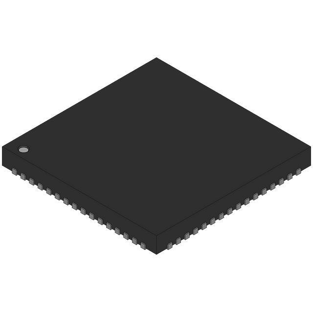
    WQFN-64_9X9MM-EP

  • 描述:

    IC ADC 16BIT PIPELINED 64WQFN

  • 详情介绍
  • 数据手册
  • 价格&库存
ADC16V130CISQE/NOPB 数据手册
National Semiconductor is now part of Texas Instruments. Search http://www.ti.com/ for the latest technical information and details on our current products and services. ADC16V130 16-Bit, 130 MSPS A/D Converter with LVDS Outputs General Description The ADC16V130 is a monolithic high performance CMOS analog-to-digital converter capable of converting analog input signals into 16-bit digital words at rates up to 130 Mega Samples Per Second (MSPS). This converter uses a differential, pipelined architecture with digital error correction and an onchip sample-and-hold circuit to minimize power consumption and external component count while providing excellent dynamic performance. Automatic power-up calibration enables excellent dynamic performance and reduces part-to-part variation, and the ADC16V130 could be re-calibrated at any time by asserting and then de-asserting power-down. An integrated low noise and stable voltage reference and differential reference buffer amplifier easies board level design. On-chip duty cycle stabilizer with low additive jitter allows wide duty cycle range of input clock without compromising its dynamic performance. A unique sample-and-hold stage yields a fullpower bandwidth of 1.4 GHz. The digital data is provided via full data rate LVDS outputs – making possible the 64-pin, 9mm x 9mm LLP package. The ADC16V130 operates on dual power supplies +1.8V and +3.0V with a power-down feature to reduce the power consumption to very low levels while allowing fast recovery to full operation. Features ■ ■ ■ ■ ■ ■ ■ ■ Offset binary or 2's complement data format ■ Full data rate LVDS output port ■ 64-pin LLP package (9x9x0.8, 0.5mm pin-pitch) Key Specifications ■ Resolution ■ Conversion Rate ■ SNR ■ ■ ■ ■ (fIN = 10MHz) (fIN = 70MHz) (fIN = 160MHz) SFDR (fIN = 10 MHz) (fIN = 70MHz) (fIN = 160MHz) Full Power Bandwidth Power Consumption Core LVDS Driver Total Operating Temperature Range 16 Bits 130 MSPS    78.5 dBFS (typ) 77.8 dBFS (typ) 76.7 dBFS (typ)    95.5 dBFS (typ) 92.0 dBFS (typ) 90.6 dBFS (typ) 1.4 GHz (typ)    650 mW (typ) 105 mW (typ) 755 mW (typ) -40°C ~ 85°C Applications Dual Supplies: 1.8V and 3.0V operation On chip automatic calibration during power-up Low power consumption Multi-level multi-function pins for CLK/DF and PD Power-down and sleep modes On chip precision reference and sample-and-hold circuit On chip low jitter duty-cycle stabilizer ■ High IF Sampling Receivers ■ Multi-carrier Base Station Receivers ■ ■ ■ ■ GSM/EDGE, CDMA2000, UMTS, LTE and WiMax Test and Measurement Equipment Communications Instrumentation Data Acquisition Portable Instrumentation Block Diagram 30062602 © 2010 National Semiconductor Corporation 300626 www.national.com ADC16V130 16-Bit, 130 MSPS A/D Converter with LVDS Outputs May 14, 2010 ADC16V130 Connection Diagram 30062601 Ordering Information Industrial (−40°C ≤ TA ≤ +85°C) www.national.com Package ADC16V130CISQ 64 Pin LLP ADC16V130EB Evaluation Board 2 ADC16V130 Pin Descriptions Pin No. Symbol Equivalent Circuit Function and Connection ANALOG I/O    VIN+ 61    VIN- 62 VRP 6,7 Differential analog input pins. The differential full-scale input signal level is 2.4Vpp as default. Each input pin signal centered on a common mode voltage, VCM. Upper reference voltage. This pin should not be used to source or sink current. The decoupling capacitor to AGND (low ESL 0.1μF) should be placed very close to the pin to minimize stray inductance. VRP needs to be connected to VRN through a low ESL 0.1μF and a low ESR 10μF capacitors in parallel. VRN 4,5 Lower reference voltage. This pin should not be used to source or sink current. The decoupling capacitor to AGND (low ESL 0.1μF) should be placed very close to the pin to minimize stray inductance. VRN needs to be connected to VRP through a low ESL 0.1μF and a low ESR 10μF capacitors in parallel. 58 57       11 VREF Internal reference voltage output / External reference voltage input. By default, this pin is the output for the internal 1.2V voltage reference. This pin should not be used to sink or source current and should be decoupled to AGND with a 0.1μF, low ESL capacitor. The decoupling capacitors should be placed as close to the pins as possible to minimize inductance and optimize ADC performance. The size of decoupling capacitor should not be larger than 0.1μF, otherwise dynamic performance after power-up calibration can drop due to the long VREF settling. This pin can also be used as the input for a low noise external reference voltage. The output impedance for the internal reference at this pin is 9 kΩ and this can be overdriven provided the impedance of the external source is
ADC16V130CISQE/NOPB
物料型号:ADC16V130

器件简介: ADC16V130是一款高性能的16位模拟-数字转换器(A/D Converter),能够以每秒高达130兆样本(MSPS)的速率将模拟输入信号转换为16位数字字。该转换器采用差分、流水线架构,具有数字错误校正和片上采样-保持电路,以最小化功耗和外部组件数量,同时提供出色的动态性能。

引脚分配: - CLK+和CLK-:差分时钟输入引脚。 - VIN:差分模拟输入引脚。 - VRP和VRN:上参考电压和下参考电压引脚。 - VREF:内部参考电压输出/外部参考电压输入引脚。 - PD:电源下状态引脚。 - D0+/-到D15+/-:LVDS数据输出引脚。

参数特性: - 分辨率:16位 - 转换速率:130 MSPS - 信噪比(SNR):在不同输入频率下有不同的典型值,例如在10MHz时为78.5 dBFS - 无杂散动态范围(SFDR):在不同输入频率下也有不同的典型值,例如在10MHz时为95.5 dBFS - 全功率带宽:1.4 GHz(典型值) - 功耗:核心650mW(典型值),LVDS驱动105mW(典型值),总计755mW(典型值)

功能详解: - 自动上电校准提供了出色的动态性能并减少了部件间差异。 - 片上低噪声稳定电压参考和差分参考缓冲放大器简化了板级设计。 - 片上低抖动占空比稳定器允许输入时钟的宽占空比范围,而不损害动态性能。 - 独特的采样-保持阶段提供了1.4 GHz的全功率带宽。 - 数字数据通过全数据速率LVDS输出提供。

应用信息: 适用于高IF采样接收器、多载波基站接收器、GSM/EDGE、CDMA2000、UMTS、LTE和WiMax等通信设备,以及便携式仪器、测试和测量设备、通信仪器和数据采集设备。

封装信息: ADC16V130采用64引脚LLP封装(9mm x 9mm x 0.8mm,0.5mm引脚间距)。
ADC16V130CISQE/NOPB 价格&库存

很抱歉,暂时无法提供与“ADC16V130CISQE/NOPB”相匹配的价格&库存,您可以联系我们找货

免费人工找货