ADS7138-Q1
SBAS977A – MAY 2020 – REVISEDADS7138-Q1
OCTOBER 2020
SBAS977A – MAY 2020 – REVISED OCTOBER 2020
www.ti.com
ADS7138-Q1 Small, 8-Channel, 12-Bit ADC With I2C Interface, GPIOs, and CRC
1 Features
2 Applications
•
•
•
•
•
•
•
•
•
•
•
•
AEC-Q100 qualified for automotive applications:
– Temperature grade 1: –40°C to +125°C, TA
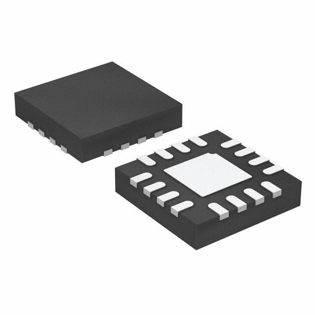
Small package size:
– 3-mm × 3-mm WQFN
– Wettable flanks for visual inspection of solder
joints
8 channels configurable as any combination of:
– Up to 8 analog inputs, digital inputs, or digital
outputs
GPIOs for I/O expansion:
– Open-drain, push-pull digital outputs
Wide operating ranges:
– AVDD: 2.35 V to 5.5 V
– DVDD: 1.65 V to 5.5 V
– –40°C to +125°C temperature range
CRC for read/write operations:
– CRC on data read/write
– CRC on power-up configuration
I2C interface:
– Up to 3.4 MHz (high-speed mode)
– 8 configurable I2C addresses
Programmable averaging filters:
– Programmable sample size for averaging
– Averaging with internal conversions
– 16-bit resolution for average output
Turbo comparator mode with speeds up to
3.2 MSPS
Camera modules without processing
Automotive center information displays
Automotive cluster displays
3 Description
The ADS7138-Q1 is an easy-to-use, 8-channel,
multiplexed, 12-bit, successive approximation register
analog-to-digital converter (SAR ADC). The eight
channels can be independently configured as either
analog inputs, digital inputs, or digital outputs. The
device has an internal oscillator for ADC conversion
processes.
The ADS7138-Q1 communicates via an I 2Ccompatible interface and operates in either
autonomous or single-shot conversion mode. The
ADS7138-Q1 implements analog watchdog function
by event-triggered interrupts per channel using a
digital window comparator with programmable high
and low thresholds, hysteresis, and an event counter.
The ADS7138-Q1 has a built-in cyclic redundancy
check (CRC) for data read/write operations and the
power-up configuration.
Device Information (1)
PART NAME
ADS7138-Q1
(1)
PACKAGE
BODY SIZE (NOM)
WQFN (16)
3.00 mm × 3.00 mm
For all available packages, see the orderable addendum at
the end of the datasheet.
Example System Architecture
Device Block Diagram
DECAP
AVDD
VCC
DVDD
AIN0 / GPIO0
AIN1 / GPIO1
ADC
AIN2 / GPIO2
AIN4 / GPIO4
AIN5 / GPIO5
AIN6 / GPIO6
AIN7 / GPIO7
MUX
ADDR
Sequencer
I2C Interface
GPO Write
GPI Read
ADC
GPIO
MUX
Pin CFG
OVP
ALERT
Programmable
Averaging Filter
Digital Window
Comparator
AIN3 / GPIO3
LOAD
AVDD
High/Low Threshold
± Hysteresis
OCP
SDA
SCL
CRC
GND
OVP: Over voltage protection
OCP: Over current protection
ADS7138-Q1 Block Diagram and Applications
An IMPORTANT NOTICE at the end of this data sheet addresses availability, warranty, changes, use in safety-critical applications,
Submit Document Feedback
Copyright
© 2020 Texas
Instruments
Incorporated
intellectual
property
matters
and other important disclaimers. PRODUCTION DATA.
Product Folder Links: ADS7138-Q1
1
�ADS7138-Q1
www.ti.com
SBAS977A – MAY 2020 – REVISED OCTOBER 2020
Table of Contents
1 Features............................................................................1
2 Applications..................................................................... 1
3 Description.......................................................................1
4 Revision History.............................................................. 2
5 Device Comparison Table...............................................3
6 Pin Configuration and Functions...................................4
Pin Functions.................................................................... 5
7 Specifications.................................................................. 6
7.1 Absolute Maximum Ratings ....................................... 6
7.2 ESD Ratings .............................................................. 6
7.3 Recommended Operating Conditions ........................6
7.4 Thermal Information ...................................................7
7.5 Electrical Characteristics ............................................8
7.6 I2C Timing Requirements ...........................................9
7.7 Timing Requirements ................................................. 9
7.8 I2C Switching Characteristics ...................................10
7.9 Switching Characteristics .........................................10
7.10 Timing Diagram....................................................... 11
7.11 Typical Characteristics............................................ 12
8 Detailed Description......................................................16
8.1 Overview................................................................... 16
8.2 Functional Block Diagram......................................... 16
8.3 Feature Description...................................................17
8.4 Device Functional Modes..........................................29
8.5 Programming............................................................ 33
8.6 ADS7138-Q1 Registers............................................ 36
9 Application and Implementation.................................. 77
9.1 Application Information............................................. 77
9.2 Typical Applications.................................................. 77
10 Power Supply Recommendations..............................79
10.1 AVDD and DVDD Supply Recommendations......... 79
11 Layout........................................................................... 80
11.1 Layout Guidelines................................................... 80
11.2 Layout Example...................................................... 80
12 Device and Documentation Support..........................81
12.1 Receiving Notification of Documentation Updates..81
12.2 Support Resources................................................. 81
12.3 Trademarks............................................................. 81
12.4 Electrostatic Discharge Caution..............................81
12.5 Glossary..................................................................81
13 Mechanical, Packaging, and Orderable
Information.................................................................... 81
4 Revision History
NOTE: Page numbers for previous revisions may differ from page numbers in the current version.
Changes from Revision * (May 2020) to Revision A (October 2020)
Page
• Changed document status from advance information to production data.......................................................... 1
2
Submit Document Feedback
Copyright © 2020 Texas Instruments Incorporated
Product Folder Links: ADS7138-Q1
�ADS7138-Q1
www.ti.com
SBAS977A – MAY 2020 – REVISED OCTOBER 2020
5 Device Comparison Table
PART NUMBER
DESCRIPTION
ADS7128
ADS7138
8-channel, 12-bit ADC with
I2C interface and GPIOs
ADS7138-Q1
CRC MODULE
ZERO-CROSSING-DETECT
(ZCD) MODULE
ROOT-MEAN-SQUARE
(RMS) MODULE
Yes
Yes
Yes
Yes
No
No
Yes
No
No
Submit Document Feedback
Copyright © 2020 Texas Instruments Incorporated
Product Folder Links: ADS7138-Q1
3
�ADS7138-Q1
www.ti.com
SBAS977A – MAY 2020 – REVISED OCTOBER 2020
AIN2/GPIO2
1
AIN3/GPIO3
2
AIN1/GPIO1
AIN0/GPIO0
SDA
SCL
16
15
14
13
6 Pin Configuration and Functions
12
ALERT
11
ADDR
10
DVDD
Thermal
7
8
AVDD
DECAP
9
6
4
AIN7/GPIO7
AIN5/GPIO5
Pad
5
3
AIN6/GPIO6
AIN4/GPIO4
GND
Not to scale
Figure 6-1. RTE Package, 16-Pin WQFN, Top View
Table 6-1. Pin Functions
PIN
NAME
4
NO.
FUNCTION(1)
DESCRIPTION
AIN0/GPIO0
15
AI, DI, DO
Channel 0; configurable as either an analog input (default) or a general-purpose
input/output (GPIO).
AIN1/GPIO1
16
AI, DI, DO
Channel 1; configurable as either an analog input (default) or a GPIO.
AIN2/GPIO2
1
AI, DI, DO
Channel 2; configurable as either an analog input (default) or a GPIO.
AIN3/GPIO3
2
AI, DI, DO
Channel 3; configurable as either an analog input (default) or a GPIO.
AIN4/GPIO4
3
AI, DI, DO
Channel 4; configurable as either an analog input (default) or a GPIO.
AIN5/GPIO5
4
AI, DI, DO
Channel 5; configurable as either an analog input (default) or a GPIO.
AIN6/GPIO6
5
AI, DI, DO
Channel 6; configurable as either an analog input (default) or a GPIO.
AIN7/GPIO7
6
AI, DI, DO
Channel 7; configurable as either an analog input (default) or a GPIO.
ADDR
11
AI
ALERT
12
Digital output
AVDD
7
Supply
Analog supply input, also used as the reference voltage to the ADC; connect a
1-µF decoupling capacitor to GND.
DECAP
8
Supply
Connect a1-µF decoupling capacitor between the DECAP and GND pins for the
internal power supply.
DVDD
10
Supply
Digital I/O supply voltage; connect a 1-µF decoupling capacitor to GND.
GND
9
Supply
Ground for the power supply; all analog and digital signals are referred to this
pin voltage.
SDA
14
DI, DO
Serial data input or output for the I2C interface.
SCL
13
DI
Thermal pad
—
Supply
Input for selecting the device I2C address.
Connect a resistor to this pin from DECAP pin or GND to select one of the eight
addresses.
Open-drain (default) or push-pull output for the digital comparator.
Serial clock for the I2C interface.
Exposed thermal pad; connect to GND.
Submit Document Feedback
Copyright © 2020 Texas Instruments Incorporated
Product Folder Links: ADS7138-Q1
�ADS7138-Q1
www.ti.com
SBAS977A – MAY 2020 – REVISED OCTOBER 2020
Pin Functions
PIN
NAME
NO.
FUNCTION(1)
DESCRIPTION
AIN0/GPIO0
15
AI, DI, DO
Channel 0; configurable as either an analog input (default) or a general-purpose
input/output (GPIO).
AIN1/GPIO1
16
AI, DI, DO
Channel 1; configurable as either an analog input (default) or a GPIO.
AIN2/GPIO2
1
AI, DI, DO
Channel 2; configurable as either an analog input (default) or a GPIO.
AIN3/GPIO3
2
AI, DI, DO
Channel 3; configurable as either an analog input (default) or a GPIO.
AIN4/GPIO4
3
AI, DI, DO
Channel 4; configurable as either an analog input (default) or a GPIO.
AIN5/GPIO5
4
AI, DI, DO
Channel 5; configurable as either an analog input (default) or a GPIO.
AIN6/GPIO6
5
AI, DI, DO
Channel 6; configurable as either an analog input (default) or a GPIO.
AIN7/GPIO7
6
AI, DI, DO
Channel 7; configurable as either an analog input (default) or a GPIO.
ADDR
11
AI
ALERT
12
Digital output
Input for selecting the device I2C address.
Connect a resistor to this pin from DECAP pin or GND to select one of the eight
addresses.
Open-drain (default) or push-pull output for the digital comparator.
AVDD
7
Supply
Analog supply input, also used as the reference voltage to the ADC; connect a
1-µF decoupling capacitor to GND.
DECAP
8
Supply
Connect a1-µF decoupling capacitor between the DECAP and GND pins for the
internal power supply.
DVDD
10
Supply
Digital I/O supply voltage; connect a 1-µF decoupling capacitor to GND.
GND
9
Supply
Ground for the power supply; all analog and digital signals are referred to this
pin voltage.
SDA
14
DI, DO
Serial data input or output for the I2C interface.
SCL
13
DI
Thermal pad
—
Supply
(1)
Serial clock for the I2C interface.
Exposed thermal pad; connect to GND.
AI = analog input, DI = digital input, and DO = digital output.
Submit Document Feedback
Copyright © 2020 Texas Instruments Incorporated
Product Folder Links: ADS7138-Q1
5
�ADS7138-Q1
www.ti.com
SBAS977A – MAY 2020 – REVISED OCTOBER 2020
7 Specifications
7.1 Absolute Maximum Ratings
over operating ambient temperature range (unless otherwise noted)(1)
MIN
MAX
DVDD to GND
–0.3
5.5
V
AVDD to GND
–0.3
5.5
V
AINx/GPOx(3)
GND – 0.3 AVDD + 0.3
V
ADDR
GND – 0.3
2.1
V
Digital inputs
GND – 0.3
5.5
V
–10
10
mA
Current through any pin except supply pins, SCL, and SDA(2)
UNIT
Junction temperature, TJ
–40
125
°C
Storage temperature, Tstg
–60
150
°C
(1)
(2)
(3)
Stresses beyond those listed under Absolute Maximum Rating may cause permanent damage to the device. These are stress ratings
only, which do not imply functional operation of the device at these or any other conditions beyond those indicated under
Recommended Operating Condition. Exposure to absolute-maximum-rated conditions for extended periods may affect device
reliability.
Pin current must be limited to 10mA or less.
AINx/GPIOx refers to pins 1, 2, 3, 4, 5, 6, 15, and 16.
7.2 ESD Ratings
VALUE
Human-body model (HBM), per AEC
V(ESD)
(1)
Electrostatic discharge
Q100-002(1)
UNIT
±2000
Charged-device model (CDM), per AEC Q100-011; corner pins (1,
4, 5, 8, 9, 12, 13, 16)
±750
Charged-device model (CDM), per AEC Q100-011; all other pins
±500
V
AEC Q100-002 indicates that HBM stressing shall be in accordance with the ANSI/ESDA/JEDEC JS-001 specification
7.3 Recommended Operating Conditions
over operating free-air temperature range (unless otherwise noted)
PARAMETER
TEST CONDITIONS
MIN
TYP
MAX
UNIT
POWER SUPPLY
AVDD
Analog supply voltage
2.35
3.3
5.5
V
DVDD
Digital supply voltage
1.65
3.3
5.5
V
0
AVDD
V
–0.1
AVDD + 0.1
V
125
℃
ANALOG INPUTS
FSR
Full-scale input range
AINX (1) - GND
VIN
Absolute input voltage
AINX - GND
TEMPERATURE RANGE
TA
(1)
6
Ambient temperature
–40
25
AINx refers to AIN0, AIN1, AIN2, AIN3, AIN4, AIN5, AIN6, and AIN7.
Submit Document Feedback
Copyright © 2020 Texas Instruments Incorporated
Product Folder Links: ADS7138-Q1
�ADS7138-Q1
www.ti.com
SBAS977A – MAY 2020 – REVISED OCTOBER 2020
7.4 Thermal Information
ADS7138-Q1
THERMAL
METRIC(1)
RTE (WQFN)
UNIT
16 PINS
RθJA
Junction-to-ambient thermal resistance
49.7
°C/W
RθJC(top)
Junction-to-case (top) thermal resistance
53.4
°C/W
RθJB
Junction-to-board thermal resistance
24.7
°C/W
ΨJT
Junction-to-top characterization parameter
1.3
°C/W
ΨJB
Junction-to-board characterization parameter
24.7
°C/W
RθJC(bot)
Junction-to-case (bottom) thermal resistance
9.3
°C/W
(1)
For more information about traditional and new thermal metrics, see the Semiconductor and IC Package Thermal Metrics application
report.
Submit Document Feedback
Copyright © 2020 Texas Instruments Incorporated
Product Folder Links: ADS7138-Q1
7
�ADS7138-Q1
www.ti.com
SBAS977A – MAY 2020 – REVISED OCTOBER 2020
7.5 Electrical Characteristics
at AVDD = 2.35 V to 5 V, DVDD = 1.65 V to 5.5 V, and maximum throughput (unless otherwise noted); minimum and
maximum values at TA = –40°C to +125°C; typical values at TA = 25°C.
PARAMETER
TEST CONDITIONS
MIN
TYP
MAX
UNIT
ANALOG INPUTS
CSH
Sampling capacitance
12
pF
DC PERFORMANCE
Resolution
DNL
Differential nonlinearity
INL
Integral nonlinearity
V(OS)
GE
No missing codes
Input offset error
Post offset calibration
Input offset thermal drift
Post offset calibration
Gain error
12
bits
–0.75
±0.2
0.75
LSB
–1.5
±0.45
1.5
LSB
–2
±0.4
2
–0.065
Gain error thermal drift
LSB
±1
ppm/°C
±0.025
0.065 %FSR
±1
ppm/°C
AC PERFORMANCE
AVDD = 5 V, fIN = 2 kHz
70
72.8
AVDD = 3 V, fIN = 2 kHz
69.8
72.4
AVDD = 5 V, fIN = 2 kHz
71.2
73
AVDD = 3 V, fIN = 2 kHz
70.5
72.5
SINAD
Signal-to-noise + distortion ratio
dB
SNR
Signal-to-noise ratio
THD
Total harmonic distortion
fIN = 2 kHz
–85
dB
SFDR
Spurious-free dynamic range
fIN = 2 kHz
91
dB
Crosstalk
100-kHz signal applied on any OFF
channel and measured on ON the
channel
–100
dB
dB
DECAP Pin
CDECAP Decoupling capacitor on DECAP pin
Voltage output on DECAP pin
0.1
CDECAP = 1 µF
1
4.7
1.8
µF
V
DIGITAL INPUT/OUTPUT (SCL, SDA)
VIH
Input high logic level
All I2C modes
0.7 x DVDD
DVDD
V
VIL
Input low logic level
All I2C modes
–0.3
0.3 x DVDD
V
VOL
Output low logic level
IOL
Low-level output current (sink)
Sink current = 2 mA, DVDD > 2 V
0
0.4
Sink current = 2 mA, DVDD ≤ 2 V
0
0.2 x DVDD
VOL = 0.4 V, standard and fast Mode
3
VOL = 0.6 V, fast mode
6
VOL = 0.4 V, fast mode plus
V
mA
20
GPIOs
VIH
Input high logic level
VIL
Input low logic level
Input leakge current
VOH
Output high logic level
0.7 x AVDD
AVDD + 0.3
–0.3
0.3 x AVDD
V
100
nA
0.8 x AVDD
AVDD
V
0
0.2 x AVDD
GPIO configured as input
GPO_DRIVE_CFG = push-pull, I
= 2 mA
SOURCE
V
10
VOL
Output low logic level
ISINK = 2 mA
IOH
Output high source current
VOH > 0.7 x AVDD
5
mA
V
IOL
Output low sink current
VOL < 0.3 x AVDD
5
mA
DIGITAL OUTPUT (ALERT)
8
VOH
Output high logic level
VOL
Output low logic level
GPO_DRIVE_CFG = push-pull, I
= 2 mA
SOURCE
ISINK = 2 mA
Submit Document Feedback
0.8 x DVDD
DVDD
V
0
0.2 x DVDD
V
Copyright © 2020 Texas Instruments Incorporated
Product Folder Links: ADS7138-Q1
�ADS7138-Q1
www.ti.com
SBAS977A – MAY 2020 – REVISED OCTOBER 2020
7.5 Electrical Characteristics (continued)
at AVDD = 2.35 V to 5 V, DVDD = 1.65 V to 5.5 V, and maximum throughput (unless otherwise noted); minimum and
maximum values at TA = –40°C to +125°C; typical values at TA = 25°C.
PARAMETER
TEST CONDITIONS
MIN
TYP
MAX
UNIT
IOH
Output high sink current
VOH > 0.7 x DVDD
5
mA
IOL
Output low sink current
VOL < 0.3 x DVDD
5
mA
POWER SUPPLY CURRENTS
I2C high-speed mode, AVDD = 5 V
IAVDD
Analog supply current
130
210
I2C fast mode plus, AVDD = 5 V
45
85
I2C fast mode, AVDD = 5 V
25
46
I2C
12
26
7
20
standard mode, AVDD = 5 V
No conversion, AVDD = 5 V
µA
7.6 I2C Timing Requirements
MODE(2)
STANDARD, FAST, AND
FAST MODE PLUS
MIN
MAX
HIGH-SPEED MODE
MIN
UNIT
MAX
fSCL
SCL clock frequency(1)
tSU;STA
Setup time for a repeated START condition
260
160
ns
tHD;STA
Hold time after repeated START condition.
After this period, the first clock is generated.
260
160
ns
tLOW
Low period of the SCL clock pin
500
160
ns
tHIGH
High period for the SCL clock pin
260
60
ns
tSU;DAT
Data in setup time
50
10
ns
tHD;DAT
Data in hold time
0
1
SCL rise time, standard mode
tR
0
MHz
ns
1000
1000
ns
SCL rise time, fast mode
300
300
ns
SCL rise time, fast mode plus
120
120
ns
SCL rise time, high-speed mode
–
80
ns
300
300
ns
SCL fall time, fast mode
300
300
ns
SCL fall time, fast mode plus
120
120
ns
SCL fall time, standard mode
tF
3.4
SCL fall time, high-speed mode
–
80
ns
tSU;STO
STOP condition hold time
260
60
ns
tBUF
Bus free time before new transmission
500
300
ns
(1)
(2)
Bus load (CB) consideration; CB ≤ 400 pF for fSCL ≤ 1 MHz; CB < 100 pF for fSCL = 3.4 MHz.
The device supports standard, full-speed, and fast modes by default on power-up. For selecting high-speed mode refer to the section
on Configuring the Device for High-Speed I2C Mode .
7.7 Timing Requirements
at AVDD = 2.35 V to 5 V, DVDD = 1.65 V to 5.5 V, and maximum throughput (unless otherwise noted); minimum and
maximum values at TA = –40°C to +125°C ; typical values at TA = 25°C.
MIN
tACQ
Acquisition time (CONV_MODE = 00b or 01b)
Acquisition time in turbo comparator mode (CONV_MODE = 10b)
300
90
MAX
UNIT
ns
Submit Document Feedback
Copyright © 2020 Texas Instruments Incorporated
Product Folder Links: ADS7138-Q1
9
�ADS7138-Q1
www.ti.com
SBAS977A – MAY 2020 – REVISED OCTOBER 2020
7.8 I2C Switching Characteristics
MODE
STANDARD, FAST, AND
FAST MODE PLUS
MIN
HIGH-SPEED MODE
MAX
MIN
UNIT
MAX
tF
Fall time for SDA
120
80
ns
tVD;DATA
SCL low to SDA data out valid
450
200
ns
tVD;DATA
SCL low to SDA data out valid
450
200
ns
tVD;ACK
SCL low to SDA acknowledge time
450
200
ns
1400
1000
ns
50
10
ns
tSTRETCH
Clock stretch time (OSR[2:0] = 000b)
tSP
Noise supression time constant on SDA and SCL
7.9 Switching Characteristics
at AVDD = 2.35 V to 5 V, DVDD = 1.65 V to 5.5 V, and maximum throughput (unless otherwise noted); minimum and
maximum values at TA = –40°C to +125°C ; typical values at TA = 25°C.
PARAMETER
TEST CONDITIONS
MIN
MAX
UNIT
CONVERSION CYCLE
Manual
Mode and AutoSequence Mode
ADC conversion time
tCONV
ADC comparison time in turbo comparator
mode
tSTRETCH
Autonomous Mode
600
Turbo Comparator
Mode
192
ns
RESET AND ALERT
tPU
Power-up time for device
tRST
Delay time; RST bit = 1b to device reset
complete(1)
tALERT_HI
ALERT high period
ALERT_LOGIC[1:0]
= 1x
tALERT_LO
ALERT low period
ALERT_LOGIC[1:0]
= 1x
(1)
10
AVDD ≥ 2.35 V
5
ms
5
ms
50
150
ns
50
150
ns
RST bit is automatically reset to 0b after tRST.
Submit Document Feedback
Copyright © 2020 Texas Instruments Incorporated
Product Folder Links: ADS7138-Q1
�ADS7138-Q1
www.ti.com
SBAS977A – MAY 2020 – REVISED OCTOBER 2020
7.10 Timing Diagram
9th clock
tLOW
tHIGH
SCL
tR
tSU;DAT
tF
tSU;STO
tSTRETCH
tHD;STA tHD;DAT
tSU;STA
tSP
SDA
tBUF
P
tVD;DAT
tF
tVD;ACK
S
Sr
P
NOTE: S = Start, Sr = Repeated Start, and P = Stop.
A. S = start, Sr = repeated start, and P = stop.
Figure 7-1. I2C Timing Diagram
Submit Document Feedback
Copyright © 2020 Texas Instruments Incorporated
Product Folder Links: ADS7138-Q1
11
�ADS7138-Q1
www.ti.com
SBAS977A – MAY 2020 – REVISED OCTOBER 2020
7.11 Typical Characteristics
at TA = 25°C, AVDD = 5 V, DVDD = 3.3 V, and maximum throughput (unless otherwise noted)
Frequency
45000
0.8
Differential Nonlinearity (LSB)
60000
39581
30000
25955
15000
0.4
0
-0.4
-0.8
0
2048
2049
0
Output Code
1024
2048
Output Code
C001
Standard deviation = 0.49 LSB
3072
4095
C002
Typical DNL = ±0.2 LSB
Figure 7-2. DC Input Histogram
Figure 7-3. Typical DNL
0.8
0.5
0.3
0.4
Differential Nonlinearity
Integral Nonlinearity (LSB)
Minimum
Maximum
0
-0.4
0.1
-0.1
-0.3
-0.8
0
1024
2048
Output Code
3072
-0.5
-40
4095
-7
C004
26
59
Temperature (°C)
92
125
C003
Typical INL = ±0.5 LSB
Figure 7-4. Typical INL
Figure 7-5. DNL vs Temperature
0.75
Differential Nonlinearity (LSB)
Integral Nonlinearity (LSB)
0.6
0.3
Minimum
Maximum
0
-0.3
-0.6
-40
-7
26
59
Temperature (°C)
92
125
C005
0.5
Maximum
Minimum
0.25
0
-0.25
-0.5
-0.75
2.5
3
3.5
4
AVDD (V)
4.5
5
5.5
C018
Figure 7-6. INL vs Temperature
Figure 7-7. DNL vs AVDD
12
Submit Document Feedback
Copyright © 2020 Texas Instruments Incorporated
Product Folder Links: ADS7138-Q1
�ADS7138-Q1
www.ti.com
SBAS977A – MAY 2020 – REVISED OCTOBER 2020
7.11 Typical Characteristics (continued)
at TA = 25°C, AVDD = 5 V, DVDD = 3.3 V, and maximum throughput (unless otherwise noted)
0.5
0.5
Maximum
Minimum
0.3
Offset Error (LSB)
Integral Nonlinearity (LSB)
0.75
0.25
0
-0.25
0.1
-0.1
-0.3
-0.5
-0.75
2.5
3
3.5
4
AVDD (V)
4.5
5
-0.5
-40
5.5
0.75
0.5
0.45
0.3
0.15
-0.15
-0.45
92
125
C006
0.1
-0.1
-0.3
-0.75
-40
-7
26
59
Temperature (°C)
92
-0.5
2.5
125
3
3.5
C007
Figure 7-10. Gain Error vs Temperature
4
AVDD (V)
4.5
5
5.5
C016
Figure 7-11. Offset Error vs AVDD
1
0
0.6
-30
Amplitude (dBFS)
Gain error (%FSR)
26
59
Temperature (°C)
Figure 7-9. Offset Error vs Temperature
Offset error (LSB)
Gain Error (%FSR)
Figure 7-8. INL vs AVDD
0.2
-0.2
-0.6
-1
2.5
-7
C019
-60
-90
-120
-150
3
3.5
4
AVDD (V)
4.5
5
5.5
0
16.7
C017
33.4
50.1
Frequency (kHz)
66.8
83.5
C008
fIN = 2 kHz, SNR = 73.2 dB, THD = 92.3 dB
Figure 7-12. Gain Error vs AVDD
Figure 7-13. Typical FFT
Submit Document Feedback
Copyright © 2020 Texas Instruments Incorporated
Product Folder Links: ADS7138-Q1
13
�ADS7138-Q1
www.ti.com
SBAS977A – MAY 2020 – REVISED OCTOBER 2020
7.11 Typical Characteristics (continued)
at TA = 25°C, AVDD = 5 V, DVDD = 3.3 V, and maximum throughput (unless otherwise noted)
11.85
73.5
73.2
11.8
73
11.775
26
59
Temperature (°C)
72.9
11.8
72.6
11.7
72.3
11.6
11.75
125
92
72
2.5
3
-87
96
-90
94.5
-91
93
91.5
125
THD (dBFS)
-89
SFDR (dBFS)
THD (dBFS)
97.5
94
92
-86
90
-88
88
-90
2.5
3.5
4
AVDD (V)
145
132
140
129
135
126
130
4.5
86
5.5
5
C012
Figure 7-17. Distortion Performance vs AVDD
IAVDD (PA)
IAVDD (PA)
3
C011
125
123
120
-7
26
59
Temperature (°C)
92
125
117
2.5
C013
Figure 7-18. Analog Supply Current vs Temperature
14
C010
-84
Figure 7-16. Distortion Performance vs Temperature
120
-40
11.5
5.5
5
THD
SFDR
-88
92
4.5
-82
99
26
59
Temperature (°C)
4
AVDD (V)
Figure 7-15. Noise Performance vs AVDD
THD
SFDR
-7
3.5
C009
Figure 7-14. Noise Performance vs Temperature
-92
-40
11.9
SFDR (dBFS)
-7
SNR, SINAD (dBFS)
11.825
72.8
-40
12
SINAD
SNR
ENOB
73.2
73.4
ENOB (Bits)
SNR, SINAD (dBFS)
SINAD
SNR
ENOB
ENOB (Bits)
73.6
3
3.5
4
AVDD (V)
4.5
5
5.5
C014
Figure 7-19. Analog Supply Current vs AVDD
Submit Document Feedback
Copyright © 2020 Texas Instruments Incorporated
Product Folder Links: ADS7138-Q1
�ADS7138-Q1
www.ti.com
SBAS977A – MAY 2020 – REVISED OCTOBER 2020
7.11 Typical Characteristics (continued)
at TA = 25°C, AVDD = 5 V, DVDD = 3.3 V, and maximum throughput (unless otherwise noted)
750
120
650
550
90
IAVDD (µA)
IAVDD (µA)
150
60
450
350
30
250
0
0
30
60
90
120
Throughput (kSPS)
150
180
150
C015
0
Figure 7-20. Analog Supply Current vs Throughput
500
1000
1500
2000
2500
Comparison Rate (kSPS)
3000
3500
C020
Figure 7-21. Analog Supply Current vs Comparison Rate
(OSC_SEL = 0) in Turbo Comparator Mode
750
40
740
34
IAVDD (µA)
IAVDD (PA)
730
28
22
720
710
16
700
10
0
20
40
60
Comparison Rate (kSPS)
80
690
-40
100
-7
26
59
Temperature (°C)
C021
Figure 7-22. Analog Supply Current vs Comparison Rate
(OSC_SEL = 1) in Turbo Comparator Mode
92
125
C022
Figure 7-23. Analog Supply Current vs Temperature
(OSC_SEL = 0, CLK_DIV = 0) in Turbo Comparator Mode
41.5
IAVDD (µA)
40.7
39.9
39.1
38.3
37.5
-40
-7
26
59
Temperature (°C)
92
125
C023
Figure 7-24. Analog Supply Current vs Temperature
(OSC_SEL = 1, CLK_DIV = 0) in Turbo Comparator Mode
Submit Document Feedback
Copyright © 2020 Texas Instruments Incorporated
Product Folder Links: ADS7138-Q1
15
�ADS7138-Q1
www.ti.com
SBAS977A – MAY 2020 – REVISED OCTOBER 2020
8 Detailed Description
8.1 Overview
The ADS7138-Q1 is a small, eight-channel, multiplexed, 12-bit, analog-to-digital converter (ADC) with an I 2Ccompatible serial interface. The eight channels of the ADS7138-Q1 can be individually configured as either
analog inputs, digital inputs, or digital outputs. The device includes a digital window comparator with a dedicated
ALERT pin that can be used to alert the host when a programmed high or low threshold is crossed on any input
channel. The device uses an internal oscillator for conversion. The ADC can be used in manual mode for
reading ADC data over the I 2C interface or in autonomous and turbo comparator modes for monitoring the
analog inputs without an active I2C interface.
The device features a programmable averaging filter that outputs a 16-bit result for enhanced resolution.
The I 2C serial interface supports standard-mode, fast-mode, fast-mode plus, and high-speed mode. The device
also features an 8-bit cyclic redundancy check (CRC) for the serial communication interface.
8.2 Functional Block Diagram
DECAP
AVDD
High/Low Threshold
± 8 x Hysteresis
DVDD
AIN0/GPIO0
AIN1/GPIO1
ADC
ALERT
Programmable
Averaging Filter
AIN2/GPIO2
Digital Window
Comparator
AIN3/GPIO3
AIN4/GPIO4
AIN5/GPIO5
AIN6/GPIO6
AIN7/GPIO7
MUX
ADDR
Sequencer
2
Pin CFG
I C Interface
GPO Write
RMS Module
GPI Read
ZCD Module
SDA
SCL
CRC
GND
16
Submit Document Feedback
Copyright © 2020 Texas Instruments Incorporated
Product Folder Links: ADS7138-Q1
�ADS7138-Q1
www.ti.com
SBAS977A – MAY 2020 – REVISED OCTOBER 2020
8.3 Feature Description
8.3.1 Multiplexer and ADC
The eight channels of the multiplexer can be independently configured as ADC inputs or general-purpose inputs/
outputs (GPIOs). As shown in Figure 8-1 every AINx/GPIOx channel has ESD protection diodes to AVDD and
GND. On power-up or after device reset, all eight multiplexer channels are configured as analog inputs.
Figure 8-1 shows an equivalent circuit for pins configured as analog inputs. The ADC sampling switch is
represented by an ideal switch (SW) in series with the resistor (R SW, typically 150 Ω), and the sampling capacitor
(CSH).
GPO_VALUE[0]
GPIO_CFG[0]
AVDD
GPI_VALUE[0]
PIN_CFG[0]
AIN0 / GPIO0
RSW
SW
MUX
Multiplexer
AVDD
CSH
ADC
AIN7 / GPIO7
PIN_CFG[7]
GPI_VALUE[7]
GPIO_CFG[7]
GPO_VALUE[7]
Figure 8-1. Analog Inputs, GPIOs, and ADC Connections
The SW switch is closed to allow the signal on the selected analog input channel to charge the internal sampling
capacitor during acquisition time. The switch SW is opened to disconnect the sampling capacitor on the ninth
falling edge of SCL.
The multiplexer channels can be configured as GPIOs using the PIN_CFG register. The direction of a GPIO
(either as an input or an output) can be set in the GPIO_CFG register. The logic level on all device channels can
be read from the GPI_VALUE register. The digital outputs can be configured by writing to the GPO_VALUE
register. The digital outputs can be configured as either open-drain or push-pull in the GPO_DRIVE_CFG
register.
8.3.2 Reference
The device uses the analog supply voltage (AVDD) as the reference for the analog-to-digital conversion process.
TI recommends connecting a 1-µF, low-equivalent series resistance (ESR) ceramic decoupling capacitor
between the AVDD and GND pins.
Submit Document Feedback
Copyright © 2020 Texas Instruments Incorporated
Product Folder Links: ADS7138-Q1
17
�ADS7138-Q1
www.ti.com
SBAS977A – MAY 2020 – REVISED OCTOBER 2020
8.3.3 ADC Transfer Function
The ADC output is in straight binary format. Equation 1 computes the ADC resolution:
1 LSB = VREF / 2N
(1)
where:
•
•
VREF = AVDD
N = 12
Figure 8-2 and Table 8-1 detail the transfer characteristics for the device.
ADC Code (Hex)
0xFFF
0x801
0x800
0x001
0x000
VIN
1 LSB
AVDD/2
(AVDD/2 + 1 LSB)
(AVDD ± 1 LSB)
Figure 8-2. Ideal Transfer Characteristics
Table 8-1. Transfer Characteristics
INPUT VOLTAGE
CODE
IDEAL OUTPUT CODE
≤1 LSB
Zero
000
1 LSB to 2 LSBs
Zero + 1
001
(AVDD / 2) to (AVDD / 2) + 1 LSB
Mid-scale code
800
(AVDD / 2) + 1 LSB to (AVDD / 2) + 2 LSB
Mid- scale code + 1
801
≥ AVDD – 1 LSB
Full-scale code
FFF
8.3.4 ADC Offset Calibration
The variation in the ADC offset error resulting from changes in temperature or AVDD can be calibrated by setting
the CAL bit in the GENERAL_CFG register. The CAL bit is reset to 0 after calibration. The host can poll the CAL
bit to check the ADC offset calibration completion status.
Multiplexer sequencing must be stopped (SEQ_START = 0b) before initiating offset calibration.
18
Submit Document Feedback
Copyright © 2020 Texas Instruments Incorporated
Product Folder Links: ADS7138-Q1
�ADS7138-Q1
www.ti.com
SBAS977A – MAY 2020 – REVISED OCTOBER 2020
8.3.5 I2C Address Selector
The I 2C address for the device is determined by connecting external resistors on the ADDR pin. The device
address is determined at power-up based on the resistor values. The device retains this address until the next
power-up event, until the next device reset, or until the device receives a command to program its own address .
Figure 8-3 shows a connection diagram for the ADDR pin and Table 8-2 lists the resistor values for selecting
different addresses of the device.
DECAP Pin
R1
ADDR
R2
Figure 8-3. External Resistor Connection Diagram for the ADDR Pin
Table 8-2. I2C Address Selection
RESISTORS
(1)
(2)
ADDRESS
R1(2)
R2(2)
0Ω
DNP(1)
001 0111b (17h)
11 kΩ
DNP
001 0110b (16h)
33 kΩ
DNP
001 0101b (15h)
100 kΩ
DNP
001 0100b (14h)
DNP
0 Ω or DNP
001 0000b (10h)
DNP
11 kΩ
001 0001b (11h)
DNP
33 kΩ
001 0010b (12h)
DNP
100 kΩ
001 0011b (13h)
DNP = Do not populate.
Tolerance for R1, R2 ≤ ±5%.
Submit Document Feedback
Copyright © 2020 Texas Instruments Incorporated
Product Folder Links: ADS7138-Q1
19
�ADS7138-Q1
www.ti.com
SBAS977A – MAY 2020 – REVISED OCTOBER 2020
8.3.6 Oscillator and Timing Control
The device uses an internal oscillator for conversions. The host initiates the first conversion and all subsequent
conversions are generated internally by the device when using the averaging module. However, in the
autonomous mode of operation, the start of the conversion signal is generated by the device. As described in
Table 8-3, the sampling rate can be controlled by the OSC_SEL and CLK_DIV register fields when the device
initiates conversions internally.
The conversion time of the device, given by t CONV in the Switching Characteristics table, is independent of the
OSC_SEL and CLK_DIV configuration.
Table 8-3. Configuring Sampling Rate for Internal Conversion Start Control
OSC_SEL = 0
20
OSC_SEL = 1
CLK_DIV[3:0]
SAMPLING FREQUENCY, f
CYCLE_OSR (kSPS)
CYCLE TIME, t
CYCLE_OSR (µs)
SAMPLING FREQUENCY, fCYCLE_OSR
(kSPS)
CYCLE TIME, t
CYCLE_OSR (µs)
0000b
1000
1
31.25
32
0001b
666.7
1.5
20.83
48
0010b
500
2
15.63
64
0011b
333.3
3
10.42
96
0100b
250
4
7.81
128
0101b
166.7
6
5.21
192
0110b
125
8
3.91
256
0111b
83
12
2.60
384
1000b
62.5
16
1.95
512
1001b
41.7
24
1.3
768
1010b
31.3
32
0.98
1024
1011b
20.8
48
0.65
1536
1100b
15.6
64
0.49
2048
1101b
10.4
96
0.33
3072
1110b
7.8
128
0.24
4096
1111b
5.2
192
0.16
6144
Submit Document Feedback
Copyright © 2020 Texas Instruments Incorporated
Product Folder Links: ADS7138-Q1
�ADS7138-Q1
www.ti.com
SBAS977A – MAY 2020 – REVISED OCTOBER 2020
The comparison time in the turbo comparator mode can be controlled by the OSC_SEL and CLK_DIV register
fields, as shown in Table 8-4.
Table 8-4. Configuring Comparison Rate for Turbo Comparator Mode
OSC_SEL = 0
CLK_DIV[3:0]
COMPARISON RATE, f
COMPARISON (kSPS)
OSC_SEL = 1
CYCLE TIME, t
(µs)
CYCLE_COMP
COMPARISON RATE, fCOMPARISON
(kSPS)
CYCLE TIME, t
(µs)
CYCLE_COMP
0000b
3200
0.3125
100
10
0001b
2133.3
0.46875
66.7
15
0010b
1600
0.625
50
20
0011b
1066.7
0.9375
33.3
30
0100b
800
1.25
25
40
0101b
533.3
1.875
16.67
60
0110b
400
2.5
12.5
80
0111b
266.7
3.75
8.33
120
1000b
200
5
6.25
160
1001b
133.3
7.5
4.17
240
1010b
100
10
3.13
320
1011b
66.7
15
2.08
480
1100b
50
20
1.56
640
1101b
33.3
30
1.04
960
1110b
25
40
0.78
1280
1111b
16.67
60
0.52
1920
8.3.7 General-Purpose I/Os (GPIOs)
The eight channels of the ADS7138-Q1 can be independently configured as analog inputs, digital inputs, or
digital outputs. The device channels, as described in Table 8-5, can be configured as analog inputs or GPIOs
using the PIN_CFG and GPIO_CFG registers.
Table 8-5. Configuring Channels as Analog Inputs or GPIOs
PIN_CFG[7:0]
GPIO_CFG[7:0]
GPO_DRIVE_CFG[7:0]
0
x
x
Analog input (default)
CHANNEL CONFIGURATION
1
0
x
Digital input
1
1
0
Digital output; open-drain driver
1
1
1
Digital output; push-pull driver
Digital outputs can be configured to logic 1 or 0 by writing to the GPO_VALUE register. Digital outputs can also
be updated in response to event flags set by the digital window comparator (see the Triggering Digital Outputs
With a Digital Window Comparator section for more details). Reading the GPI_VALUE register returns the logic
level for all channels configured as analog inputs, digital inputs, and digital outputs.
Submit Document Feedback
Copyright © 2020 Texas Instruments Incorporated
Product Folder Links: ADS7138-Q1
21
�ADS7138-Q1
www.ti.com
SBAS977A – MAY 2020 – REVISED OCTOBER 2020
8.3.8 Programmable Averaging Filter
The ADS7138-Q1 features a built-in oversampling (OSR) module that can be used to average several samples.
The averaging filter can be enabled by programming the OSR[2:0] bits in the OSR_CFG register. The averaging
filter configuration is common to all analog input channels. As shown in Figure 8-4, the averaging filter module
output is 16 bits long. Only the first conversion for the selected analog input channel must be initiated by the
host. Any remaining conversions for the selected averaging factor are generated internally. The time required to
complete the averaging operation is determined by the sampling speed and number of samples to be averaged;
see the Oscillator and Timing Control section. The 16-bit result can be read out after the averaging operation
completes. For more information about programmable averaging filters and performance results, see the
Resolution-Boosting ADS7138 Using Programmable Averaging Filter appliction report.
Sample AINX
S
7-bit ADDR
R
A
Sample AINX
Sample AINX
Sample AINX
OSR_DONE = 1
Bus idle or Poll OSR_DONE bit
DATA[15:8]
A
DATA[7:0]
A
OSR_DONE = 0
OSR_CFG[2:0] = 2
Maximum tAVG = N samples x t CYCLE_OSR x 1.06
Data from host to device
Data from device to host
Figure 8-4. Averaging Example
As shown in Figure 8-4, SCL is stretched by the device after the start of conversions until the averaging
operation is complete.
If SCL stretching is not required during averaging, enable the statistics registers by setting STATS_EN to 1b and
initiate conversions by writing 1b to the CNVST bit. The OSR_DONE bit in the SYSTEM_STATUS register can
be polled to check the averaging completion status. When using the CNVST bit to initiate conversion, the result
can be read in the RECENT_CHx_LSB and RECENT_CHx_MSB registers.
In the autonomous mode of operation, samples from the analog input channels that are enabled in the
AUTO_SEQ_CH_SEL register are averaged sequentially; see the Autonomous Mode section. The digital
window comparator compares the top 12 bits of the 16-bit average result with the thresholds.
Equation 2 provides the LSB value of the 16-bit average result.
1 LSB
AVDD
216
(2)
8.3.9 CRC on Data Interface
The cyclic redundancy check (CRC) is an error checking code that detects errors in communication between the
device and the host. The CRC module is optional and can be enabled by the CRC_EN bit in the
GENERAL_CFG register.
The CRC data byte is the 8-bit remainder of the bitwise exclusive-OR (XOR) operation of the argument by a
CRC polynomial. The CRC polynomial is based on the CRC-8-CCITT: X 8 + X 2 + X + 1. The nine binary
polynomial coefficients are 100000111. The CRC calculation is preset with 0 data values.
8.3.9.1 Input CRC (From Host To Device)
The host must compute the appropriate 8-bit CRC corresponding to the 8-bit I2C data (see Figure 8-5). The ADC
also computes the expected 8-bit CRC corresponding to the 8-bit data received from the host and compares the
calculated CRC code to the CRC received from the host. The host must not send a CRC byte corresponding to
the I2C frame containing the device address.
22
Submit Document Feedback
Copyright © 2020 Texas Instruments Incorporated
Product Folder Links: ADS7138-Q1
�ADS7138-Q1
www.ti.com
S
SBAS977A – MAY 2020 – REVISED OCTOBER 2020
7-bit Slave Address
W
A
Byte 1
A
CRC for Byte 1
Data from host to device
A
Byte 2
A
CRC for Byte 2
A
Data from device to host
NOTE: S = Start, Sr = Repeated Start, and P = Stop.
Figure 8-5. I2C Write With a CRC
If a CRC error is detected by the device, the command does not execute, and the CRCERR_IN flag is set to 1b.
The ADC conversion data read and register read, with a valid CRC from the host, are still supported. The error
condition can be detected, as listed in Table 8-6, by either status flags or by a register read. Further register
writes to the device are blocked until the CRCERR_IN flag is cleared to 0b. Register write operations, with a
valid CRC from the host, to the SYSTEM_STATUS and GENERAL_CFG registers are still supported.
The device can be configured to set all channels to analog inputs on detecting a CRC error by setting the
CH_RST bit to 1b. This setting ensures channels configured as digital outputs are not driven by the device when
a CRC error is detected. All channels are reset as per the configuration in the PIN_CFG and GPIO_CFG
registers when the CRCERR_IN flag is cleared.
The device can be configured to abort further conversions in autonomous and turbo comparator modes (see the
Autonomous Mode and Turbo Comparator Mode sections), on detecting a CRC error, by setting
CONV_ON_ERR = 1b.
Table 8-6. Configuring Notifications When a CRC Error is Detected
CRC ERROR NOTIFICATION
CONFIGURATION
DESCRIPTION
ALERT
ALERT_CRCIN = 1b
ALERT pin is asserted if a CRC error is detected.
Status flags
APPEND_STATUS = 10b
See the Status Flags section for details.
Register read
—
Read the CRCERR_IN bit to check if a CRC error was detected.
8.3.9.2 Output CRC (From Device to Host)
As shown in Figure 8-6, the device sends an 8-bit CRC corresponding to every byte sent by the device over the I
2C interface.
S
7-bit Slave Address
R
A
Byte 1
A
CRC for Byte 1
Data from host to device
A
Byte 2
A
CRC for Byte 2
A
Data from device to host
NOTE: S = Start, Sr = Repeated Start, and P = Stop.
Figure 8-6. I2C Read With CRC
8.3.10 Output Data Format
Figure 8-7 illustrates various I2C frames for reading data.
• Read the ADC conversion result: Two 8-bit I2C packets are required (frame A).
• Read the averaged conversion result: Two 8-bit I2C packets are required (frame B).
• Read data with the channel ID or status flags appended: The 4-bit channel ID or status flags can be
appended to the 12-bit ADC result by configuring the APPEND_STATUS field in the GENERAL_CFG register.
The status flags can be used to detect if a CRC error is detected and if an alert condition is detected by the
digital window comparator. When the channel ID or status flags are appended to the 12-bit ADC data, two I2C
packets are required (frame C). If the channel ID or status flags are appended to the 16-bit average result,
three I2C frames are required (frame D).
When the CRC module is enabled, the device sends an 8-bit CRC for every 8-bit data byte sent over the I 2C
interface; see the Output CRC (From Device to Host) section for more details.
Submit Document Feedback
Copyright © 2020 Texas Instruments Incorporated
Product Folder Links: ADS7138-Q1
23
�ADS7138-Q1
www.ti.com
SBAS977A – MAY 2020 – REVISED OCTOBER 2020
Sample A
S
7-bit Slave Address
R
A
Sample A + 1
D11
D10
D9
D8
D7
D6
D5
D4
A
D3
D2
D1
D0
0
0
0
0
A
D7
D6
D5
D4
D3
D2
D1
D0
A
D1
D0
Frame A : Reading ADC data
S
7-bit Slave Address
R
A
D15
D14
D13
D12
D11
D10
D9
D8
A
Frame B : Reading ADC data with averaging enabled
S
7-bit Slave Address
R
A
D11
D10
D9
D8
D7
D6
D5
D4
A
D3
D2
4-bit Channel ID
or Status Flags
A
Frame C : Reading ADC data with status flags or channel ID appended
S
7-bit Slave Address
R
A
Clock stretching for conversion time
D15
D14
D8
A
D7
D6
D0
A
4-bit Channel ID
or Status Flags
0
0
0
0
A
Frame D : Reading ADC data with averaging enabled &
status flags or channel ID appended
Data from host to device
Data from device to host
Figure 8-7. Data Frames for Reading Data
When status flags are enabled, APPEND_STATUS is set to 10b and four bits are appended to the ADC output.
The device outputs status flags in this order: {1b, 0b, CRCERR_IN, ALERT}. The level transitions on the digital
interface, resulting from the fixed 1b and 0b in the status flags, can be used to detect if the digital outputs are
shorted to a fixed voltage in the system. The CRCERR_IN flag reflects the corresponding bit in the
GENERAL_CFG register. The ALERT flag is the output of the logical OR of the bits in the EVENT_FLAG
register.
8.3.10.1 Status Flags
Status flags can be enabled by setting APPEND_STATUS = 10b. As shown in Figure 8-7, four additional bits are
appended to the ADC output when status flags are enabled.
The device outputs status flags in this order: {1b, 0b, CRCERR_IN, ALERT}. The CRCERR_IN flag reflects the
corresponding bit in the GENERAL_CFG register. The ALERT flag is the output of the logical OR of the bits in
the EVENT_FLAG register.
24
Submit Document Feedback
Copyright © 2020 Texas Instruments Incorporated
Product Folder Links: ADS7138-Q1
�ADS7138-Q1
www.ti.com
SBAS977A – MAY 2020 – REVISED OCTOBER 2020
8.3.11 Digital Window Comparator
The digital window comparator (DWC) compares the conversion result for an analog input channel with
programmable high and low thresholds with hysteresis. As shown in Figure 8-8, the DWC sets the
EVENT_HIGH_FLAG and EVENT_LOW_FLAG registers based on the comparison result sounds better. The
logical OR of the EVENT_HIGH_FLAG and EVENT_LOW_FLAG registers is available in the EVENT_FLAG
register. The ALERT pin is asserted when a bit in the EVENT_FLAG register is high and the corresponding bit in
the ALERT_CH_SEL register is enabled.
The ALERT pin can be configured as open-drain (default) or push-pull output using the ALERT_DRIVE bit in the
ALERT_PIN_CFG register.
EVENT_RGN[7]
EVENT_FLAG
EVENT_RGN[0]
Digital input CH0
High threshold Hysteresis
ADC
EVENT_HIGH_FLAG[0]
MUX
Programmable
Averaging Filter
EVENT_LOW_FLAG[0]
ALERT_CH_SEL
12-bit ADC data
or
[15:4] Average result
Event
Counter
Low threshold +
Hysteresis
ALERT
PIN_CFG[0]
All registers are specific for
individual analog input channels
GPIO_CFG[0]
Figure 8-8. Digital Window Comparator Block Diagram
The low-side threshold, high-side threshold, event counter, and hysteresis parameters are independently
programmable for each input channel. Figure 8-9 shows the events that can be monitored for every analog input
channel by the window comparator.
0xFFF
0xFFF
High threshold ± 8 x Hysteresis
Signal above limit
Digital code
Digital code
High threshold ± 8 x Hysteresis
Low threshold + 8 x Hysteresis
Signal below limit
Low threshold + 8 x Hysteresis
0x000
0x000
Samples
0xFFF
Samples
0xFFF
Signal out of band
High threshold ± 8 x Hysteresis
Digital code
Digital code
High threshold ± 8 x Hysteresis
EVENT_RGN = 0
Low threshold + 8 x Hysteresis
Low threshold + 8 x Hysteresis
EVENT_RGN = 1
Signal out of band
0x000
Signal in band
0x000
Samples
Samples
Figure 8-9. Event Monitoring With the Window Comparator
To enable the digital window comparator, set the DWC_EN bit in the GENERAL_CFG register. By default,
hysteresis is 0, the high threshold is 0xFFF, and the low threshold is 0x000. Configure the EVENT_RGN register
to detect when a signal is within a band defined by the high and low thresholds. In each of the cases shown in
Figure 8-9, either or both EVENT_HIGH_FLAG and EVENT_LOW_FLAG can be set.
Submit Document Feedback
Copyright © 2020 Texas Instruments Incorporated
Product Folder Links: ADS7138-Q1
25
�ADS7138-Q1
www.ti.com
SBAS977A – MAY 2020 – REVISED OCTOBER 2020
The device features a programmable event counter that counts consecutive threshold violations before either
EVENT_HIGH_FLAG or EVENT_LOW_FLAG are set. An example is shown in Figure 8-10 where the
EVENT_HIGH_FLAG is not set until eight consecutive conversion results of the corresponding analog input
channel exceed the threshold configuration. The event count can be set to a higher value to avoid transients in
the input signal from setting the event flags.
EVENT_COUNT_CHx = 8
(waits for 8 counts to set alert)
1
2 3
2
1
High Threshold
4
5
6
3
7
8
High Threshold t 8 x Hysteresis
0
Event counter is reset because the
high-side-comparator is reset before
8 samples exceed high threshold.
High Side Comparator
(Internal Only Signal)
EVENT_HIGH_FLAG
Figure 8-10. False Trigger Avoidance Using the Event Counter
In order to assert the ALERT pin when the alert flag is set for a particular analog input channel, set the
corresponding bit in the ALERT_CH_SEL register.
26
Submit Document Feedback
Copyright © 2020 Texas Instruments Incorporated
Product Folder Links: ADS7138-Q1
�ADS7138-Q1
www.ti.com
SBAS977A – MAY 2020 – REVISED OCTOBER 2020
8.3.11.1 Interrupts From Digital Inputs
Rising edge or falling edge events can be detected on channels configured as digital inputs. As described in
Table 8-7, configure the EVENT_RGN register to select either a rising edge or falling edge event.
Table 8-7. Configuring Interrupts From Digital Inputs
PIN_CFG[7:0]
GPIO_CFG[7:0]
EVENT_RGN [7:0]
EVENT DESCRIPTION
1
0
0
A rising edge on the digital input sets the
corresponding flag in the EVENT_HIGH_FLAG
register.
1
0
1
A falling edge on the digital input sets the
corresponding flag in the EVENT_LOW_FLAG
register.
8.3.11.2 Triggering Digital Outputs With a Digital Window Comparator
As shown in Figure 8-11, the output value of channels configured as digital outputs can be updated in response
to one or more flags being set in the EVENT_FLAG register.
Digital output 7
Digital output 0
Select device channels for which corresponding
bits in EVENT_FLAG should trigger GPO0
GPO0_EVENT_SEL[7:0]
trigger
GPO_UPDATE_ON_EVENT [0]
Enable the selected EVENT_FLAG bits to trigger
GPO00
Default
0
GPO_VALUE [0]
1
GPO_VALUE_ON_EVENT [0]
Output value when one of the selected
events is asserted
Figure 8-11. Block Diagram of the Digital Output Logic
The following procedure enables updating the output value of a digital output in response to event flags:
1. Configure the device channels as either analog inputs (default), digital inputs, or digital outputs.
2. Configure the digital outputs as either open-drain (default) or push-pull outputs.
3. Configure the digital window comparator for the input channels. The digital window comparator updates the
flags in the EVENT_FLAG register corresponding to individual channels. See the Digital Window Comparator
section for more details.
4. Select the bits corresponding to the input channels that are to be enabled for triggering the digital output in
the GPOx_EVENT_SEL register (where x is the digital output channel number).
5. The default output value of the digital output, when no event flag is set, is configured in the GPO_VALUE
register. The output value of the digital output, when event flags are set, is configured in the
GPO_VALUE_ON_EVENT register.
Submit Document Feedback
Copyright © 2020 Texas Instruments Incorporated
Product Folder Links: ADS7138-Q1
27
�ADS7138-Q1
www.ti.com
SBAS977A – MAY 2020 – REVISED OCTOBER 2020
6. Configure the GPO_UPDATE_ON_EVENT register to enable the logic to update the selected digital output in
response to event flags.
The configuration in GPO_VALUE sets the output value of a dgital output when either no event flags are set or
when event flags are reset in the EVENT_FLAG register corresponding to channels selected in the
GPOx_EVENT_SEL register.
8.3.12 Minimum, Maximum, and Latest Data Registers
The ADS7138-Q1 can record the minimum, maximum, and latest code (statistics registers) for every analog
input channel. To enable or re-enable recording statistics, set the STATS_EN bit in the GENERAL_CFG register.
Writing 1 to the STATS_EN bit reinitializes the statistics module. Previous values can be read from the statistics
registers until a new conversion result is available. Set STATS_EN = 0b to prevent any updates to this block of
registers before reading the statistics registers.
8.3.13 I2C Protocol Features
8.3.13.1 General Call
On receiving a general call (00h), the device provides an acknowledge (ACK).
8.3.13.2 General Call With Software Reset
On receiving a general call (00h) followed by a software reset (06h), the device resets itself.
8.3.13.3 General Call With a Software Write to the Programmable Part of the Slave Address
On receiving a general call (00h) followed by 04h, the device reevaluates its own I 2C address configured by the
ADDR pin. During this operation, the device does not respond to other I 2C commands except the general-call
command.
8.3.13.4 Configuring the Device for High-Speed I2C Mode
The device can be configured in high-speed I 2C mode by providing an I 2C frame with one of these codes: 0x09,
0x0B, 0x0D, or 0x0F.
After receiving one of these codes, the device sets the I 2C_SPEED bit in the SYSTEM_STATUS register and
remains in high-speed I2C mode until a STOP condition is received in an I2C frame.
28
Submit Document Feedback
Copyright © 2020 Texas Instruments Incorporated
Product Folder Links: ADS7138-Q1
�ADS7138-Q1
www.ti.com
SBAS977A – MAY 2020 – REVISED OCTOBER 2020
8.4 Device Functional Modes
Table 8-8 lists the functional modes supported by the ADS7138-Q1. The device powers up in manual mode (see
the Manual Mode section) and can be configured into any mode listed in Table 8-8 by writing the configuration
registers for the desired mode.
Table 8-8. Functional Modes
FUNCTIONAL MODE
CONVERSION CONTROL
CONV_MODE[1:0]
SEQ_MODE[1:0]
Manual
Register write to
9th falling edge of SCL (ACK)
MANUAL_CHID
MUX CONTROL
00b
00b
Auto-sequence
9th falling edge of SCL (ACK) Channel sequencer
00b
01b
Autonomous
Internal to the device
Channel sequencer
01b
01b
Turbo comparator
Internal to the device
Channel sequencer
10b
01b
8.4.1 Device Power-Up and Reset
On power-up, the device calculates the address from the resistors connected on the ADDR pin and the BOR bit
is set, thus indicating a power-cycle or reset event.
The device can be reset by an I 2C general call (00h) followed by a software reset (06h), by setting the RST bit,
or by recycling the power on the AVDD pin.
8.4.2 Manual Mode
Manual mode allows the external host processor to directly select the analog input channel. Figure 8-12 lists the
steps for operating the device in manual mode.
Idle
SEQ_MODE = 0b
CONV_MODE = 0b
Configure channels as AIN/GPIO using PIN_CFG
Calibrate offset error (CAL = 1b)
Select Manual mode
(CONV_MODE = 00b, SEQ_MODE = 00b)
Configure desired Channel ID in MANUAL_CHID field
Host provides Conversion Start Frame on I2C Bus
Host provides Conversion Read Frame on I2C Bus
No
Same
Channel ID?
Yes
Manual mode with channel selection using register write
Figure 8-12. Device Operation in Manual Mode
Provide an I2C start or restart frame to initiate a conversion, as illustrated in the conversion start frame of Figure
8-13, after configuring the device registers. ADC data can be read in subsequent I2C frames. The number of I2C
frames required to read conversion data depends on the output data frame size; see the Output Data Format
Submit Document Feedback
Copyright © 2020 Texas Instruments Incorporated
Product Folder Links: ADS7138-Q1
29
�ADS7138-Q1
www.ti.com
SBAS977A – MAY 2020 – REVISED OCTOBER 2020
section for more details. A new conversion is initiated on the ninth falling edge of SCL (ACK bit) when the last
byte of output data is read.
Sample A + 1
Sample A
S
7-bit Slave Address
R
A
Clock stretching for conversion time
8 bit I2C frame
A
8 bit I2C frame
A
8 bit I2C frame
A
8 bit I2C frame
A
Clock stretching for conversion time
Data from host to device
Data from device to host
Figure 8-13. Starting a Conversion and Reading Data in Manual Mode
8.4.3 Auto-Sequence Mode
In auto-sequence mode, the internal channel sequencer switches the multiplexer to the next analog input
channel after every conversion. The desired analog input channels can be configured for sequencing in the
AUTO_SEQ_CH_SEL register. To enable the channel sequencer, set SEQ_START to 1b. After every
conversion, the channel sequencer switches the multiplexer to the next analog input in ascending order. To stop
the channel sequencer from selecting channels, set SEQ_START to 0b. Figure 8-14 lists the conversion start
and read frames for auto-sequence mode.
Idle
SEQ_MODE = 0b
CONV_MODE = 0b
Configure channels as AIN/GPIO using PIN_CFG
Calibrate offset error (CAL = 1b)
Enable analog inputs for sequencing (AUTO_SEQ_CH_SEL)
Select Auto-sequence mode (SEQ_MODE = 01b)
(optional) Configure alert conditions
(optional) Append Channel ID to data using APPEND_STATUS
Enable channel sequencing SEQ_START = 1b
Host provides Conversion Start Frame on I2C Bus
Host provides Conversion Read Frame on I2C Bus
Device selects next channel according to AUTO_SEQ_CH_SEL
Continue?
Yes
No
Disable channel sequencing SEQ_START = 0b
Idle
Figure 8-14. Device Operation in Auto-Sequence Mode
30
Submit Document Feedback
Copyright © 2020 Texas Instruments Incorporated
Product Folder Links: ADS7138-Q1
�ADS7138-Q1
www.ti.com
SBAS977A – MAY 2020 – REVISED OCTOBER 2020
8.4.4 Autonomous Mode
In autonomous mode, the device can be programmed to monitor the voltage applied on the analog input pins of
the device and generate a signal on the ALERT pin when the programmable high or low threshold values are
crossed. In this mode, the device generates the start of conversion using the internal oscillator. The first start of
conversion must be provided by the host and the device then generates the subsequent start of conversions.
Figure 8-15 shows the steps for configuring the operation mode to autonomous mode. Abort the ongoing
sequence by setting SEQ_START to 0b before changing the functional mode or device configuration.
Idle
SEQ_MODE = 0b
CONV_MODE = 0b
Configure channels as AIN/GPIO using PIN_CFG
Calibrate offset error (CAL = 1b)
Channel
selection
Enable analog inputs for sequencing (AUTO_SEQ_CH_SEL)
Select Auto-sequence mode (SEQ_MODE = 01b)
Configure alert condition using HIGH_TH_CHx,
LOW_TH_CHx,EVENT_COUNT_CHx, HYSTERESIS_CHx, and
EVENT_REGION_CHx fields
Enable analog inputs to trigger ALERT pin using ALERT_CH_SEL
Configuration
Threshold & Alert
configuration
Configure ALERT pin using ALERT_DRIVE and ALERT_LOGIC fields
Configure sampling rate of analog inputs using OSC_SEL and CLK_DIV
Set mode to autonomous monitoring (CONV_MODE = 01b)
Sampling rate
configuration
(optional) Enable averaging and min/max recording (OSR[2:0] and STATS_EN)
Enable threshold comparison (DWC_EN = 1b)
Enable autonomous monitoring (SEQ_START = 1b)
Active Operation
(Digital
communication
interface can be idle)
No
ALERT?
(optional) read conversion results in
MIN_VALUE_CHx, MAX_VALUE_CHx, and
LAST_VALUE_CHx registers
Yes
Stop autonomous monitoring (SEQ_START = 0b)
Disable threshold comparison (DWC_EN = 0b)
ALERT Detected
Read alert flags ± EVENT_FLAG, EVENT_HIGH_FLAG, EVENT_LOW_FLAG
Clear alert flags ± EVENT_HIGH_FLAG, EVENT_LOW_FLAG
Figure 8-15. Configuring the Device in Autonomous Mode
Submit Document Feedback
Copyright © 2020 Texas Instruments Incorporated
Product Folder Links: ADS7138-Q1
31
�ADS7138-Q1
www.ti.com
SBAS977A – MAY 2020 – REVISED OCTOBER 2020
8.4.5 Turbo Comparator Mode
Turbo comparator mode allows fast comparison with high and low thresholds using the digital window
comparator. ADC output data are not available in this mode.
Figure 8-16 lists the comparison start and read frames for turbo comparator mode. The desired analog input
channels can be configured for sequencing in the AUTO_SEQ_CH_SEL register. To enable the channel
sequencer, set SEQ_START to 1b. After every comparison, the channel sequencer switches the multiplexer to
the next analog input in ascending order. To stop the channel sequencer from selecting channels, set
SEQ_START to 0b. See the Oscillator and Timing Control section for more details on configuring the speed in
turbo comparator mode.
Abort the ongoing sequence by setting SEQ_START to 0b before changing the functional mode or device
configuration.
Idle
SEQ_MODE = 0b
CONV_MODE = 0b
Configure channels as AIN/GPIO using PIN_CFG
Calibrate offset error (CAL = 1b)
Channel
selection
Enable analog inputs for sequencing (AUTO_SEQ_CH_SEL)
Select auto-sequence mode (SEQ_MODE = 01b)
Configure alert condition using HIGH_TH_CHx,
LOW_TH_CHx,EVENT_COUNT_CHx, HYSTERESIS_CHx, and
EVENT_REGION_CHx fields
Enable analog inputs to trigger ALERT pin using ALERT_CH_SEL
Threshold & Alert
configuration
Configuration
Configure ALERT pin using ALERT_DRIVE and ALERT_LOGIC fields
Configure sampling rate of analog inputs using OSC_SEL and CLK_DIV
Select turbo comparator mode (CONV_MODE = 10b)
Sampling rate
configuration
Enable threshold comparison (DWC_EN = 1b)
Start turbo comparator mode (SEQ_START = 1b)
Active Operation
(Digital
communication
interface can be idle)
No
ALERT?
Yes
Stop turbo comparator mode (SEQ_START = 0b)
Disable threshold comparison (DWC_EN = 0b)
ALERT Detected
Read alert flags ± EVENT_FLAG, EVENT_HIGH_FLAG, EVENT_LOW_FLAG
Clear alert flags ± EVENT_HIGH_FLAG, EVENT_LOW_FLAG
Figure 8-16. Device Operation in Turbo Comparator Mode
32
Submit Document Feedback
Copyright © 2020 Texas Instruments Incorporated
Product Folder Links: ADS7138-Q1
�ADS7138-Q1
www.ti.com
SBAS977A – MAY 2020 – REVISED OCTOBER 2020
8.5 Programming
Table 8-9 provides the acronyms for different conditions in an I 2C frame. Table 8-10 lists the various command
opcodes.
Table 8-9. I2C Frame Acronyms
SYMBOL
DESCRIPTION
S
Start condition for the I2C frame
Sr
Restart condition for the I2C frame
P
Stop condition for the I2C frame
A
ACK (low)
N
NACK (high)
R
Read bit (high)
W
Write bit (low)
Table 8-10. Opcodes for Commands
OPCODE
COMMAND DESCRIPTION
0001 0000b
Single register read
0000 1000b
Single register write
0001 1000b
Set bit
0010 0000b
Clear bit
0011 0000b
Reading a continuous block of registers
0010 1000b
Writing a continuous block of registers
8.5.1 Register Read
The I2C master can either read a single register or a continuous block registers from the device, as described in
the Single Register Read and Reading a Continuous Block of Registers sections.
8.5.1.1 Single Register Read
To read a single register from the device, the I2C master must provide an I2C command with three frames to set
the register address for reading data. The opcodes for commands supported by the device are listed in Table
8-10. After an I 2C command is provided, the I 2C master must provide another I 2C frame (as shown in Figure
8-17) containing the device address and the read bit. The device provides the register data in the next I2C frame.
The device provides the same register data even if the host provides more I 2C frames. To end the register read
command, the master must provide a STOP or a RESTART condition in the I2C frame.
S
7-bit Slave Address
W
A
0001 0000b
A
Register
Address
Data from host to device
A
P/Sr
S
7-bit Slave Address
R
A
Register Data
A
P/Sr
Data from device to host
S = start, Sr = repeated start, and P = stop.
Figure 8-17. Single Register Read
Submit Document Feedback
Copyright © 2020 Texas Instruments Incorporated
Product Folder Links: ADS7138-Q1
33
�ADS7138-Q1
www.ti.com
SBAS977A – MAY 2020 – REVISED OCTOBER 2020
8.5.1.2 Reading a Continuous Block of Registers
To read a continuous block of registers, the I 2C master must provide an I 2C command to set the register
address. The register address is the address of the first register in the block that must be read. After this
command is provided, the I 2C master must provide another I 2C frame, as shown in Figure 8-18, containing the
device address and the read bit. After this frame, the device provides the register data. The device provides data
for the next register when more clocks are provided. When data are read from addresses that do not exist in the
register map of the device, the device returns zeros. If the device does not have any further registers to provide
data on, the device provide zeros. To end the register read command, the master must provide a STOP or a
RESTART condition in the I2C frame.
S
7-bit Slave Address
W
A
0011 0000b
A
1st Reg Address
in the Block
A
Data from host to device
P/Sr
S
7-bit Slave Address
R
A
Register Data
A
P/Sr
Data from device to host
S = start, Sr = repeated start, and P = stop.
Figure 8-18. Reading a Continuous Block of Registers
8.5.2 Writing Registers
The I 2C master can either write a single register or a continuous block of registers to the device, set a few bits in
a register, or clear a few bits in a register.
8.5.2.1 Single Register Write
To write a single register from the device, as shown in Figure 8-19, the I2C master must provide an I2C command
with four frames. The register address is the address of the register that must be written and the register data is
the value that must be written. Table 8-10 lists the opcodes for different commands. To end the register write
command, the master must provide a STOP or a RESTART condition in the I2C frame.
S
7-bit Slave Address
W
A
0000 1000b
Data from host to device
A
Register
Address
A
Register Data
A
P/Sr
Data from device to host
S = start, Sr = repeated start, and P = stop.
Figure 8-19. Writing a Single Register
8.5.2.2 Set Bit
The I2C master must provide an I2C command with four frames, as shown in Figure 8-19, to set bits in a register
without changing the other bits. The register address is the address of the register that the bits must set and the
register data is the value representing the bits that must be set. Bits with a value of 1 in the register data are set
and bits with a value of 0 in the register data are not changed. Table 8-10 lists the opcodes for different
commands. To end this command, the master must provide a STOP or RESTART condition in the I2C frame.
8.5.2.3 Clear Bit
The I 2C master must provide an I 2C command with four frames, as shown in Figure 8-19, to clear bits in a
register without changing the other bits. The register address is the address of the register that the bits must
clear and the register data is the value representing the bits that must be cleared. Bits with a value of 1 in the
register data are cleared and bits with a value of 0 in the register data are not changed. Table 8-10 lists the
opcodes for different commands. To end this command, the master must provide a STOP or a RESTART
condition in the I2C frame.
34
Submit Document Feedback
Copyright © 2020 Texas Instruments Incorporated
Product Folder Links: ADS7138-Q1
�ADS7138-Q1
www.ti.com
SBAS977A – MAY 2020 – REVISED OCTOBER 2020
8.5.2.4 Writing a Continuous Block of Registers
The I2C master must provide an I2C command, as shown in Figure 8-20, to write a continuous block of registers.
The register address is the address of the first register in the block that must be written. The I 2C master must
provide data for registers in subsequent I 2C frames in an ascending order of register addresses. Writing data to
addresses that do not exist in the register map of the device have no effect. Table 8-10 lists the opcodes for
different commands. If the data provided by the I2C master exceeds the address space of the device, the device
ignores the data beyond the address space. To end the register write command, the master must provide a
STOP or a RESTART condition in the I2C frame.
S
7-bit Slave Address
W
A
0010 1000b
A
1st Reg Address
in the block
Data from host to device
A
Register Data
A
P/Sr
Data from device to host
S = start, Sr = repeated start, and P = stop.
Figure 8-20. Writing a Continuous Block of Registers
Submit Document Feedback
Copyright © 2020 Texas Instruments Incorporated
Product Folder Links: ADS7138-Q1
35
�ADS7138-Q1
www.ti.com
SBAS977A – MAY 2020 – REVISED OCTOBER 2020
8.6 ADS7138-Q1 Registers
Table 8-11 lists the memory-mapped registers for the ADS7138-Q1 registers. All register offset addresses not
listed in Table 8-11 should be considered as reserved locations and the register contents should not be modified.
Table 8-11. ADS7138-Q1 Registers
Address
36
Acronym
Register Name
Section
0x0
SYSTEM_STATUS
Section 8.6.1
0x1
GENERAL_CFG
Section 8.6.2
0x2
DATA_CFG
Section 8.6.3
0x3
OSR_CFG
Section 8.6.4
0x4
OPMODE_CFG
Section 8.6.5
0x5
PIN_CFG
Section 8.6.6
0x7
GPIO_CFG
Section 8.6.7
0x9
GPO_DRIVE_CFG
Section 8.6.8
0xB
GPO_VALUE
Section 8.6.9
0xD
GPI_VALUE
Section 8.6.10
0x10
SEQUENCE_CFG
Section 8.6.11
0x11
MANUAL_CH_SEL
Section 8.6.12
0x12
AUTO_SEQ_CH_SEL
Section 8.6.13
0x14
ALERT_CH_SEL
Section 8.6.14
0x16
ALERT_FUNC_SEL
Section 8.6.15
0x17
ALERT_PIN_CFG
Section 8.6.16
0x18
EVENT_FLAG
Section 8.6.17
0x1A
EVENT_HIGH_FLAG
Section 8.6.18
0x1C
EVENT_LOW_FLAG
Section 8.6.19
0x1E
EVENT_RGN
Section 8.6.20
0x20
HYSTERESIS_CH0
Section 8.6.21
0x21
HIGH_TH_CH0
Section 8.6.22
0x22
EVENT_COUNT_CH0
Section 8.6.23
0x23
LOW_TH_CH0
Section 8.6.24
0x24
HYSTERESIS_CH1
Section 8.6.25
0x25
HIGH_TH_CH1
Section 8.6.26
0x26
EVENT_COUNT_CH1
Section 8.6.27
0x27
LOW_TH_CH1
Section 8.6.28
0x28
HYSTERESIS_CH2
Section 8.6.29
0x29
HIGH_TH_CH2
Section 8.6.30
0x2A
EVENT_COUNT_CH2
Section 8.6.31
0x2B
LOW_TH_CH2
Section 8.6.32
0x2C
HYSTERESIS_CH3
Section 8.6.33
0x2D
HIGH_TH_CH3
Section 8.6.34
0x2E
EVENT_COUNT_CH3
Section 8.6.35
0x2F
LOW_TH_CH3
Section 8.6.36
0x30
HYSTERESIS_CH4
Section 8.6.37
0x31
HIGH_TH_CH4
Section 8.6.38
0x32
EVENT_COUNT_CH4
Section 8.6.39
0x33
LOW_TH_CH4
Section 8.6.40
0x34
HYSTERESIS_CH5
Section 8.6.41
Submit Document Feedback
Copyright © 2020 Texas Instruments Incorporated
Product Folder Links: ADS7138-Q1
�ADS7138-Q1
www.ti.com
SBAS977A – MAY 2020 – REVISED OCTOBER 2020
Table 8-11. ADS7138-Q1 Registers (continued)
Address
Acronym
Register Name
Section
0x35
HIGH_TH_CH5
Section 8.6.42
0x36
EVENT_COUNT_CH5
Section 8.6.43
0x37
LOW_TH_CH5
Section 8.6.44
0x38
HYSTERESIS_CH6
Section 8.6.45
0x39
HIGH_TH_CH6
Section 8.6.46
0x3A
EVENT_COUNT_CH6
Section 8.6.47
0x3B
LOW_TH_CH6
Section 8.6.48
0x3C
HYSTERESIS_CH7
Section 8.6.49
0x3D
HIGH_TH_CH7
Section 8.6.50
0x3E
EVENT_COUNT_CH7
Section 8.6.51
0x3F
LOW_TH_CH7
Section 8.6.52
0x60
MAX_CH0_LSB
Section 8.6.53
0x61
MAX_CH0_MSB
Section 8.6.54
0x62
MAX_CH1_LSB
Section 8.6.55
0x63
MAX_CH1_MSB
Section 8.6.56
0x64
MAX_CH2_LSB
Section 8.6.57
0x65
MAX_CH2_MSB
Section 8.6.58
0x66
MAX_CH3_LSB
Section 8.6.59
0x67
MAX_CH3_MSB
Section 8.6.60
0x68
MAX_CH4_LSB
Section 8.6.61
0x69
MAX_CH4_MSB
Section 8.6.62
0x6A
MAX_CH5_LSB
Section 8.6.63
0x6B
MAX_CH5_MSB
Section 8.6.64
0x6C
MAX_CH6_LSB
Section 8.6.65
0x6D
MAX_CH6_MSB
Section 8.6.66
0x6E
MAX_CH7_LSB
Section 8.6.67
0x6F
MAX_CH7_MSB
Section 8.6.68
0x80
MIN_CH0_LSB
Section 8.6.69
0x81
MIN_CH0_MSB
Section 8.6.70
0x82
MIN_CH1_LSB
Section 8.6.71
0x83
MIN_CH1_MSB
Section 8.6.72
0x84
MIN_CH2_LSB
Section 8.6.73
0x85
MIN_CH2_MSB
Section 8.6.74
0x86
MIN_CH3_LSB
Section 8.6.75
0x87
MIN_CH3_MSB
Section 8.6.76
0x88
MIN_CH4_LSB
Section 8.6.77
0x89
MIN_CH4_MSB
Section 8.6.78
0x8A
MIN_CH5_LSB
Section 8.6.79
0x8B
MIN_CH5_MSB
Section 8.6.80
0x8C
MIN_CH6_LSB
Section 8.6.81
0x8D
MIN_CH6_MSB
Section 8.6.82
0x8E
MIN_CH7_LSB
Section 8.6.83
0x8F
MIN_CH7_MSB
Section 8.6.84
0xA0
RECENT_CH0_LSB
Section 8.6.85
0xA1
RECENT_CH0_MSB
Section 8.6.86
Submit Document Feedback
Copyright © 2020 Texas Instruments Incorporated
Product Folder Links: ADS7138-Q1
37
�ADS7138-Q1
www.ti.com
SBAS977A – MAY 2020 – REVISED OCTOBER 2020
Table 8-11. ADS7138-Q1 Registers (continued)
Address
Acronym
Register Name
Section
0xA2
RECENT_CH1_LSB
Section 8.6.87
0xA3
RECENT_CH1_MSB
Section 8.6.88
0xA4
RECENT_CH2_LSB
Section 8.6.89
0xA5
RECENT_CH2_MSB
Section 8.6.90
0xA6
RECENT_CH3_LSB
Section 8.6.91
0xA7
RECENT_CH3_MSB
Section 8.6.92
0xA8
RECENT_CH4_LSB
Section 8.6.93
0xA9
RECENT_CH4_MSB
Section 8.6.94
0xAA
RECENT_CH5_LSB
Section 8.6.95
0xAB
RECENT_CH5_MSB
Section 8.6.96
0xAC
RECENT_CH6_LSB
Section 8.6.97
0xAD
RECENT_CH6_MSB
Section 8.6.98
0xAE
RECENT_CH7_LSB
Section 8.6.99
0xAF
RECENT_CH7_MSB
Section 8.6.100
0xC3
GPO0_TRIG_EVENT_SEL
Section 8.6.101
0xC5
GPO1_TRIG_EVENT_SEL
Section 8.6.102
0xC7
GPO2_TRIG_EVENT_SEL
Section 8.6.103
0xC9
GPO3_TRIG_EVENT_SEL
Section 8.6.104
0xCB
GPO4_TRIG_EVENT_SEL
Section 8.6.105
0xCD
GPO5_TRIG_EVENT_SEL
Section 8.6.106
0xCF
GPO6_TRIG_EVENT_SEL
Section 8.6.107
0xD1
GPO7_TRIG_EVENT_SEL
Section 8.6.108
0xE9
GPO_TRIGGER_CFG
Section 8.6.109
0xEB
GPO_VALUE_TRIG
Section 8.6.110
Complex bit access types are encoded to fit into small table cells. Table 8-12 shows the codes that are used for
access types in this section.
Table 8-12. ADS7138-Q1 Access Type Codes
Access Type
Code
Description
R
Read
W
Write
Read Type
R
Write Type
W
Reset or Default Value
-n
Value after reset or the default
value
Register Array Variables
i,j,k,l,m,n
38
When these variables are used in
a register name, an offset, or an
address, they refer to the value of
a register array where the register
is part of a group of repeating
registers. The register groups
form a hierarchical structure and
the array is represented with a
formula.
Submit Document Feedback
Copyright © 2020 Texas Instruments Incorporated
Product Folder Links: ADS7138-Q1
�ADS7138-Q1
www.ti.com
SBAS977A – MAY 2020 – REVISED OCTOBER 2020
Table 8-12. ADS7138-Q1 Access Type Codes
(continued)
Access Type
Code
Description
y
When this variable is used in a
register name, an offset, or an
address it refers to the value of a
register array.
8.6.1 SYSTEM_STATUS Register (Address = 0x0) [Reset = 0x81]
SYSTEM_STATUS is shown in Figure 8-17 and described in Table 8-13.
Return to the Table 8-11.
Figure 8-17. SYSTEM_STATUS Register
7
6
5
4
3
2
1
0
RSVD
SEQ_STATUS
I2C_SPEED
RESERVED
OSR_DONE
CRC_ERR_FU
SE
CRC_ERR_IN
BOR
R-1b
R-0b
R-0b
R-0b
R/W-0b
R-0b
R/W-0b
R/W-1b
Table 8-13. SYSTEM_STATUS Register Field Descriptions
Bit
Field
Type
Reset
Description
7
RSVD
R
1b
Reads return 1b.
6
SEQ_STATUS
R
0b
Status of the channel sequencer.
0b = Sequence stopped
1b = Sequence in progress
5
I2C_SPEED
R
0b
I2C high-speed status.
0b = I2C bus is not in high-speed mode.
1b = I2C bus is in high-speed mode.
4
RESERVED
R
0b
Reserved Bit
3
OSR_DONE
R/W
0b
Averaging status. Clear this bit by writing 1b to this bit.
0b = Averaging in progress or not started; average result is not
ready.
1b = Averaging complete; average result is ready.
2
CRC_ERR_FUSE
R
0b
Device power-up configuration CRC check status. To re-evaluate this
bit, software reset the device or power cycle AVDD.
0b = No problems detected in power-up configuration.
1b = Device configuration not loaded correctly.
1
CRC_ERR_IN
R/W
0b
Status of CRC check on incoming data. Write 1b to clear this error
flag.
0b = No CRC error.
1b = CRC error detected. All register writes, except to addresses
0x00 and 0x01, are blocked.
0
BOR
R/W
1b
Brown out reset indicator. This bit is set if brown out condition occurs
or device is power cycled. Write 1b to this bit to clear the flag.
0b = No brown out condition detected from last time this bit was
cleared.
1b = Brown out condition detected or device power cycled.
8.6.2 GENERAL_CFG Register (Address = 0x1) [Reset = 0x0]
GENERAL_CFG is shown in Figure 8-18 and described in Table 8-14.
Return to the Table 8-11.
Figure 8-18. GENERAL_CFG Register
7
6
5
4
3
2
1
0
Submit Document Feedback
Copyright © 2020 Texas Instruments Incorporated
Product Folder Links: ADS7138-Q1
39
�ADS7138-Q1
www.ti.com
SBAS977A – MAY 2020 – REVISED OCTOBER 2020
Figure 8-18. GENERAL_CFG Register (continued)
RESERVED
CRC_EN
STATS_EN
DWC_EN
CNVST
CH_RST
CAL
RST
R-0b
R/W-0b
R/W-0b
R/W-0b
W-0b
R/W-0b
R/W-0b
W-0b
Table 8-14. GENERAL_CFG Register Field Descriptions
Bit
Field
Type
Reset
Description
7
RESERVED
R
0b
Reserved Bit
6
CRC_EN
R/W
0b
Enable or disable the CRC on device interface.
0b = CRC module disabled.
1b = CRC appended to data output. CRC check is enabled on
incoming data.
5
STATS_EN
R/W
0b
Enable or disable the statistics module to update minimu, maximum,
and latest output code registers.
0b = Statistics registers are not updated.
1b = Clear statistics registers and conitnue updating with new
conversion results.
4
DWC_EN
R/W
0b
Enable or disable the digital window comparator.
0b = Reset or disable the digital window comparator.
1b = Enable the digital window comparator.
3
CNVST
W
0b
Control start conversion on selected analog input. Readback of this
bit returns 0b.
0b = Normal operation; conversions starts on the 9th falling edge of I
2C frame. Device stretches SCL until end of conversion or
completion of averaging.
1b = Initiate start of conversion. Device does not stretch SCL until
end of conversion or completion of averaging.
2
CH_RST
R/W
0b
Force all channels to be analog inputs.
0b = Normal operation.
1b = All channels are configured as analog inputs irrespective of
configuration in other registers.
1
CAL
R/W
0b
Calibrate ADC offset.
0b = Normal operation.
1b = ADC offset is calibrated. After calibration is complete, this bit is
set to 0b by the device.
0
RST
W
0b
Software reset all registers to default values.
0b = Normal operation.
1b = Device is reset. After reset is complete, this bit is set to 0b and
BOR bit is set to 1b by the device.
8.6.3 DATA_CFG Register (Address = 0x2) [Reset = 0x0]
DATA_CFG is shown in Figure 8-19 and described in Table 8-15.
Return to the Table 8-11.
Figure 8-19. DATA_CFG Register
7
6
FIX_PAT
RESERVED
APPEND_STATUS[1:0]
5
4
3
2
RESERVED
1
R/W-0b
R-0b
R/W-0b
R-0b
0
Table 8-15. DATA_CFG Register Field Descriptions
Bit
40
Field
Type
Reset
Description
7
FIX_PAT
R/W
0b
Device will output fixed data bits, which can be helpful for debugging
communication with the device.
0b = Normal operation.
1b = Device outputs fixed code 0xA5A repeatitively when reading
data.
6
RESERVED
R
0b
Reserved Bit
Submit Document Feedback
Copyright © 2020 Texas Instruments Incorporated
Product Folder Links: ADS7138-Q1
�ADS7138-Q1
www.ti.com
SBAS977A – MAY 2020 – REVISED OCTOBER 2020
Table 8-15. DATA_CFG Register Field Descriptions (continued)
Bit
Field
Type
Reset
Description
5-4
APPEND_STATUS[1:0]
R/W
0b
Append 4-bit channel ID or status flags to output data.
0b = Channel ID and status flags are not appended to ADC data.
1b = 4-bit channel ID is appended to ADC data.
10b = 4-bit status flags are appended to ADC data.
11b = Reserved.
3-0
RESERVED
R
0b
Reserved Bit
8.6.4 OSR_CFG Register (Address = 0x3) [Reset = 0x0]
OSR_CFG is shown in Figure 8-20 and described in Table 8-16.
Return to the Table 8-11.
Figure 8-20. OSR_CFG Register
7
6
5
4
3
2
1
RESERVED
OSR[2:0]
R-0b
R/W-0b
0
Table 8-16. OSR_CFG Register Field Descriptions
Bit
Field
Type
Reset
Description
7-3
RESERVED
R
0b
Reserved Bit
2-0
OSR[2:0]
R/W
0b
Selects the oversampling ratio for ADC conversion result.
0b = No averaging
1b = 2 samples
10b = 4 samples
11b = 8 samples
100b = 16 samples
101b = 32 samples
110b = 64 samples
111b = 128 samples
8.6.5 OPMODE_CFG Register (Address = 0x4) [Reset = 0x0]
OPMODE_CFG is shown in Figure 8-21 and described in Table 8-17.
Return to the Table 8-11.
Figure 8-21. OPMODE_CFG Register
7
6
5
4
3
2
1
CONV_ON_ER
R
CONV_MODE[1:0]
OSC_SEL
CLK_DIV[3:0]
R/W-0b
R/W-0b
R/W-0b
R/W-0b
0
Table 8-17. OPMODE_CFG Register Field Descriptions
Bit
7
Field
Type
Reset
Description
CONV_ON_ERR
R/W
0b
Control continuation of autonomous and turbo comparator modes if
CRC error is detected on communication interface.
0b = If CRC error is detected, device continues channel sequencing
and pin configuration is retained. See the CRC_ERR_IN bit for more
details.
1b = If CRC error is detected, device changes all channels to analog
inputs and channel sequencing is paused until CRC_ERR_IN = 1b.
After clearing CRC_ERR_IN flag, device resumes channel
sequencing and pin confguration is restored.
Submit Document Feedback
Copyright © 2020 Texas Instruments Incorporated
Product Folder Links: ADS7138-Q1
41
�ADS7138-Q1
www.ti.com
SBAS977A – MAY 2020 – REVISED OCTOBER 2020
Table 8-17. OPMODE_CFG Register Field Descriptions (continued)
Bit
Field
Type
Reset
Description
6-5
CONV_MODE[1:0]
R/W
0b
These bits set the mode of conversion of the ADC.
0b = Manual mode; conversions are initiated by host.
1b = Autonomous mode; conversions are initiated by internal state
machine.
10b = Turbo mode; comparisons are initiated by internal state
machine.
OSC_SEL
R/W
0b
Selects the oscillator for internal timing generation.
0b = High-speed oscillator.
1b = Low-power oscillator.
CLK_DIV[3:0]
R/W
0b
Sampling speed control. See the section on oscillator and timing
control for details.
4
3-0
8.6.6 PIN_CFG Register (Address = 0x5) [Reset = 0x0]
PIN_CFG is shown in Figure 8-22 and described in Table 8-18.
Return to the Table 8-11.
Figure 8-22. PIN_CFG Register
7
6
5
4
3
2
1
0
PIN_CFG[7:0]
R/W-0b
Table 8-18. PIN_CFG Register Field Descriptions
Bit
Field
Type
Reset
Description
7-0
PIN_CFG[7:0]
R/W
0b
Configure device channels AIN/GPIO[7:0] as analog inputs or
GPIOs.
0b = Channel is configured as an analog input.
1b = Channel is configured as a GPIO.
8.6.7 GPIO_CFG Register (Address = 0x7) [Reset = 0x0]
GPIO_CFG is shown in Figure 8-23 and described in Table 8-19.
Return to the Table 8-11.
Figure 8-23. GPIO_CFG Register
7
6
5
4
3
2
1
0
GPIO_CFG[7:0]
R/W-0b
Table 8-19. GPIO_CFG Register Field Descriptions
Bit
Field
Type
Reset
Description
7-0
GPIO_CFG[7:0]
R/W
0b
Configure GPIO[7:0] as either digital inputs or digital outputs.
0b = GPIO is configured as digital input.
1b = GPIO is configured as digital output.
8.6.8 GPO_DRIVE_CFG Register (Address = 0x9) [Reset = 0x0]
GPO_DRIVE_CFG is shown in Figure 8-24 and described in Table 8-20.
Return to the Table 8-11.
42
Submit Document Feedback
Copyright © 2020 Texas Instruments Incorporated
Product Folder Links: ADS7138-Q1
�ADS7138-Q1
www.ti.com
SBAS977A – MAY 2020 – REVISED OCTOBER 2020
Figure 8-24. GPO_DRIVE_CFG Register
7
6
5
4
3
2
1
0
GPO_DRIVE_CFG[7:0]
R/W-0b
Table 8-20. GPO_DRIVE_CFG Register Field Descriptions
Bit
Field
Type
Reset
Description
7-0
GPO_DRIVE_CFG[7:0]
R/W
0b
Configure digital outputs GPO[7:0] as either open-drain or push-pull
outputs.
0b = Digital output is open-drain; connect external pullup resistor.
1b = Push-pull driver is used for digital output.
8.6.9 GPO_VALUE Register (Address = 0xB) [Reset = 0x0]
GPO_VALUE is shown in Figure 8-25 and described in Table 8-21.
Return to the Table 8-11.
Figure 8-25. GPO_VALUE Register
7
6
5
4
3
2
1
0
GPO_VALUE[7:0]
R/W-0b
Table 8-21. GPO_VALUE Register Field Descriptions
Bit
Field
Type
Reset
Description
7-0
GPO_VALUE[7:0]
R/W
0b
Logic level to be set on digital outputs GPO[7:0].
0b = Digital output is set to logic 0.
1b = Digital output is set to logic 1.
8.6.10 GPI_VALUE Register (Address = 0xD) [Reset = 0x0]
GPI_VALUE is shown in Figure 8-26 and described in Table 8-22.
Return to the Table 8-11.
Figure 8-26. GPI_VALUE Register
7
6
5
4
3
2
1
0
GPI_VALUE[7:0]
R-0b
Table 8-22. GPI_VALUE Register Field Descriptions
Bit
Field
Type
Reset
Description
7-0
GPI_VALUE[7:0]
R
0b
This field returns the logical level of all channels including analog
inputs, digital inputs, and digital outputs.
0b = GPIO is at logic 0.
1b = GPIO is at logic 1.
8.6.11 SEQUENCE_CFG Register (Address = 0x10) [Reset = 0x0]
SEQUENCE_CFG is shown in Figure 8-27 and described in Table 8-23.
Return to the Table 8-11.
Figure 8-27. SEQUENCE_CFG Register
7
6
5
4
3
2
1
0
Submit Document Feedback
Copyright © 2020 Texas Instruments Incorporated
Product Folder Links: ADS7138-Q1
43
�ADS7138-Q1
www.ti.com
SBAS977A – MAY 2020 – REVISED OCTOBER 2020
Figure 8-27. SEQUENCE_CFG Register (continued)
RESERVED
SEQ_START
RESERVED
SEQ_MODE[1:0]
R-0b
R/W-0b
R-0b
R/W-0b
Table 8-23. SEQUENCE_CFG Register Field Descriptions
Bit
Field
Type
Reset
Description
7-5
RESERVED
R
0b
Reserved Bit
4
SEQ_START
R/W
0b
Control for start of channel sequence when using auto sequence
mode (SEQ_MODE = 01b).
0b = Stop channel sequencing.
1b = Start channel sequencing in ascending order for channels
enabled in AUTO_SEQ_CH_SEL register.
3-2
RESERVED
R
0b
Reserved Bit
1-0
SEQ_MODE[1:0]
R/W
0b
Selects the mode of scanning of analog input channels.
0b = Manual sequence mode; channel selected by MANUAL_CHID
field.
1b = Auto sequence mode; channel selected by
AUTO_SEQ_CH_SEL.
10b = Reserved.
11b = Reserved.
8.6.12 MANUAL_CH_SEL Register (Address = 0x11) [Reset = 0x0]
MANUAL_CH_SEL is shown in Figure 8-28 and described in Table 8-24.
Return to the Table 8-11.
Figure 8-28. MANUAL_CH_SEL Register
7
6
5
4
3
2
1
RESERVED
MANUAL_CHID[3:0]
R-0b
R/W-0b
0
Table 8-24. MANUAL_CH_SEL Register Field Descriptions
Bit
Field
Type
Reset
Description
7-4
RESERVED
R
0b
Reserved Bit
3-0
MANUAL_CHID[3:0]
R/W
0b
In manual mode (SEQ_MODE = 00b), this field contains the 4-bit
channel ID of the analog input channel for next ADC conversion. For
valid ADC data, the selected channel must not be configured as
GPIO in PIN_CFG register.
0b = AIN0
1b = AIN1
10b = AIN2
11b = AIN3
100b = AIN4
101b = AIN5
110b = AIN6
111b = AIN7
1000b = Reserved.
8.6.13 AUTO_SEQ_CH_SEL Register (Address = 0x12) [Reset = 0x0]
AUTO_SEQ_CH_SEL is shown in Figure 8-29 and described in Table 8-25.
Return to the Table 8-11.
Figure 8-29. AUTO_SEQ_CH_SEL Register
7
6
5
4
3
2
1
0
AUTO_SEQ_CH_SEL[7:0]
44
Submit Document Feedback
Copyright © 2020 Texas Instruments Incorporated
Product Folder Links: ADS7138-Q1
�ADS7138-Q1
www.ti.com
SBAS977A – MAY 2020 – REVISED OCTOBER 2020
Figure 8-29. AUTO_SEQ_CH_SEL Register (continued)
R/W-0b
Table 8-25. AUTO_SEQ_CH_SEL Register Field Descriptions
Bit
Field
7-0
AUTO_SEQ_CH_SEL[7:0] R/W
Type
Reset
Description
0b
Select analog input channels AIN[7:0] in for auto sequencing mode.
0b = Analog input channel is not enabled in scanning sequence.
1b = Analog input channel is enabled in scanning sequence.
8.6.14 ALERT_CH_SEL Register (Address = 0x14) [Reset = 0x0]
ALERT_CH_SEL is shown in Figure 8-30 and described in Table 8-26.
Return to the Table 8-11.
Figure 8-30. ALERT_CH_SEL Register
7
6
5
4
3
2
1
0
ALERT_CH_SEL[7:0]
R/W-0b
Table 8-26. ALERT_CH_SEL Register Field Descriptions
Bit
Field
Type
Reset
Description
7-0
ALERT_CH_SEL[7:0]
R/W
0b
Select channels for which the alert flags can assert the ALERT pin.
0b = Event flags for this channel do not assert the ALERT pin.
1b = Event flags for this channel assert the ALERT pin.
8.6.15 ALERT_FUNC_SEL Register (Address = 0x16) [Reset = 0x0]
ALERT_FUNC_SEL is shown in Figure 8-31 and described in Table 8-27.
Return to the Table 8-11.
Figure 8-31. ALERT_FUNC_SEL Register
7
6
5
4
3
2
1
0
RESERVED
ALERT_CRCIN
R-0b
R/W-0b
Table 8-27. ALERT_FUNC_SEL Register Field Descriptions
Bit
Field
Type
Reset
Description
7-1
RESERVED
R
0b
Reserved Bit
ALERT_CRCIN
R/W
0b
Enable or disable the alert notification for CRC error on input data
(CRCERR_IN = 1b).
0b = ALERT pin is not asserted when CRCERR_IN = 1b.
1b = ALERT pin is asserted when CRCERR_IN = 1b. Clear
CRCERR_IN for deasserting the ALERT pin.
0
8.6.16 ALERT_PIN_CFG Register (Address = 0x17) [Reset = 0x0]
ALERT_PIN_CFG is shown in Figure 8-32 and described in Table 8-28.
Return to the Table 8-11.
Figure 8-32. ALERT_PIN_CFG Register
7
6
5
4
3
RESERVED
2
ALERT_DRIVE
1
0
ALERT_LOGIC[1:0]
Submit Document Feedback
Copyright © 2020 Texas Instruments Incorporated
Product Folder Links: ADS7138-Q1
45
�ADS7138-Q1
www.ti.com
SBAS977A – MAY 2020 – REVISED OCTOBER 2020
Figure 8-32. ALERT_PIN_CFG Register (continued)
R-0b
R/W-0b
R/W-0b
Table 8-28. ALERT_PIN_CFG Register Field Descriptions
Bit
Field
Type
Reset
Description
7-3
RESERVED
R
0b
Reserved Bit
ALERT_DRIVE
R/W
0b
Configure output drive of the ALERT pin.
0b = Open-drain output. Connect external pullup resistor.
1b = Push-pull output.
ALERT_LOGIC[1:0]
R/W
0b
Configure how ALERT pin is asserted.
0b = Active low.
1b = Active high.
10b = Pulsed low (one logic low pulse every time a bit in
EVENT_FLAG is set to 1b).
11b = Pulsed high (one logic high pulse every time a bit in
EVENT_FLAG is set to 1b).
2
1-0
8.6.17 EVENT_FLAG Register (Address = 0x18) [Reset = 0x0]
EVENT_FLAG is shown in Figure 8-33 and described in Table 8-29.
Return to the Table 8-11.
Figure 8-33. EVENT_FLAG Register
7
6
5
4
3
2
1
0
EVENT_FLAG[7:0]
R-0b
Table 8-29. EVENT_FLAG Register Field Descriptions
Bit
Field
Type
Reset
Description
7-0
EVENT_FLAG[7:0]
R
0b
Event flags indicating digital window comparator status for AIN/
GPIO[7:0]. Clear individual bits of EVENT_HIGH_FLAG or
EVENT_LOW_FLAG registers to clear the corresponding bit in this
register.
0b = Event condition not detected.
1b = Event condition detected.
8.6.18 EVENT_HIGH_FLAG Register (Address = 0x1A) [Reset = 0x0]
EVENT_HIGH_FLAG is shown in Figure 8-34 and described in Table 8-30.
Return to the Table 8-11.
Figure 8-34. EVENT_HIGH_FLAG Register
7
6
5
4
3
2
1
0
EVENT_HIGH_FLAG[7:0]
R/W-0b
Table 8-30. EVENT_HIGH_FLAG Register Field Descriptions
46
Bit
Field
Type
7-0
EVENT_HIGH_FLAG[7:0] R/W
Reset
Description
0b
Event flag corresponding to high threshold of analog input or logic 1
on digital input on AIN/GPIO[7:0]. Write 1b to clear this flag.
0b = No alert condition detected.
1b = Either high threshold was exceeded (analog input) or logic 1
was detected (digital input).
Submit Document Feedback
Copyright © 2020 Texas Instruments Incorporated
Product Folder Links: ADS7138-Q1
�ADS7138-Q1
www.ti.com
SBAS977A – MAY 2020 – REVISED OCTOBER 2020
8.6.19 EVENT_LOW_FLAG Register (Address = 0x1C) [Reset = 0x0]
EVENT_LOW_FLAG is shown in Figure 8-35 and described in Table 8-31.
Return to the Table 8-11.
Figure 8-35. EVENT_LOW_FLAG Register
7
6
5
4
3
2
1
0
EVENT_LOW_FLAG[7:0]
R/W-0b
Table 8-31. EVENT_LOW_FLAG Register Field Descriptions
Bit
Field
Type
Reset
Description
7-0
EVENT_LOW_FLAG[7:0]
R/W
0b
Event orresponding to low threshold of analog input or logic 0 on
digital input on AIN/GPIO[7:0]. Write 1b to clear this flag.
0b = No Event condition detected.
1b = Either low threshold was exceeded (analog input) or logic 0 was
detected (digital input).
8.6.20 EVENT_RGN Register (Address = 0x1E) [Reset = 0x0]
EVENT_RGN is shown in Figure 8-36 and described in Table 8-32.
Return to the Table 8-11.
Figure 8-36. EVENT_RGN Register
7
6
5
4
3
2
1
0
EVENT_RGN[7:0]
R/W-0b
Table 8-32. EVENT_RGN Register Field Descriptions
Bit
Field
Type
Reset
Description
7-0
EVENT_RGN[7:0]
R/W
0b
Choice of region used in monitoring analog and digital inputs AIN/
GPIO[7:0].
0b = Event flag is set if: (conversion result < low threshold) or
(conversion result > high threshold). For digital inputs, logic 1 sets
the alert flag.
1b = Event flag is set if: (low threshold > conversion result < high
threshold). For digital inputs, logic 0 sets the eventt flag.
8.6.21 HYSTERESIS_CH0 Register (Address = 0x20) [Reset = 0xF0]
HYSTERESIS_CH0 is shown in Figure 8-37 and described in Table 8-33.
Return to the Table 8-11.
Figure 8-37. HYSTERESIS_CH0 Register
7
6
5
4
3
2
1
HIGH_THRESHOLD_CH0_LSB[3:0]
HYSTERESIS_CH0[3:0]
R/W-1111b
R/W-0b
0
Table 8-33. HYSTERESIS_CH0 Register Field Descriptions
Bit
Field
7-4
HIGH_THRESHOLD_CH0 R/W
_LSB[3:0]
Type
Reset
Description
1111b
Lower 4-bits of high threshold for analog input. These bits are
compared with bits 3:0 of ADC conversion result.
Submit Document Feedback
Copyright © 2020 Texas Instruments Incorporated
Product Folder Links: ADS7138-Q1
47
�ADS7138-Q1
www.ti.com
SBAS977A – MAY 2020 – REVISED OCTOBER 2020
Table 8-33. HYSTERESIS_CH0 Register Field Descriptions (continued)
Bit
Field
Type
Reset
Description
3-0
HYSTERESIS_CH0[3:0]
R/W
0b
4-bit hysteresis for high and low thresholds. This 4-bit hysteris is left
shifted 3 times and applied on the lower 7-bits of the threshold. Total
hysteresis = 7-bits [4-bits, 000b]
8.6.22 HIGH_TH_CH0 Register (Address = 0x21) [Reset = 0xFF]
HIGH_TH_CH0 is shown in Figure 8-38 and described in Table 8-34.
Return to the Table 8-11.
Figure 8-38. HIGH_TH_CH0 Register
7
6
5
4
3
2
1
0
HIGH_THRESHOLD_CH0_MSB[7:0]
R/W-11111111b
Table 8-34. HIGH_TH_CH0 Register Field Descriptions
Bit
Field
7-0
HIGH_THRESHOLD_CH0 R/W
_MSB[7:0]
Type
Reset
Description
11111111b
MSB aligned high threshold for analog input. These bits are
compared with top 8 bits of ADC conversion result.
8.6.23 EVENT_COUNT_CH0 Register (Address = 0x22) [Reset = 0x0]
EVENT_COUNT_CH0 is shown in Figure 8-39 and described in Table 8-35.
Return to the Table 8-11.
Figure 8-39. EVENT_COUNT_CH0 Register
7
6
5
4
3
2
1
LOW_THRESHOLD_CH0_LSB[3:0]
EVENT_COUNT_CH0[3:0]
R/W-0b
R/W-0b
0
Table 8-35. EVENT_COUNT_CH0 Register Field Descriptions
Bit
Field
Reset
Description
7-4
LOW_THRESHOLD_CH0 R/W
_LSB[3:0]
Type
0b
Lower 4-bits of low threshold for analog input. These bits are
compared with bits 3:0 of ADC conversion result.
3-0
EVENT_COUNT_CH0[3:0 R/W
]
0b
Configuration for checking 'n+1' consecutive samples above
threshold before setting event flag.
8.6.24 LOW_TH_CH0 Register (Address = 0x23) [Reset = 0x0]
LOW_TH_CH0 is shown in Figure 8-40 and described in Table 8-36.
Return to the Table 8-11.
Figure 8-40. LOW_TH_CH0 Register
7
6
5
4
3
2
1
0
LOW_THRESHOLD_CH0_MSB[7:0]
R/W-0b
48
Submit Document Feedback
Copyright © 2020 Texas Instruments Incorporated
Product Folder Links: ADS7138-Q1
�ADS7138-Q1
www.ti.com
SBAS977A – MAY 2020 – REVISED OCTOBER 2020
Table 8-36. LOW_TH_CH0 Register Field Descriptions
Bit
Field
7-0
LOW_THRESHOLD_CH0 R/W
_MSB[7:0]
Type
Reset
Description
0b
MSB aligned high threshold for analog input. These bits are
compared with top 8 bits of ADC conversion result.
8.6.25 HYSTERESIS_CH1 Register (Address = 0x24) [Reset = 0xF0]
HYSTERESIS_CH1 is shown in Figure 8-41 and described in Table 8-37.
Return to the Table 8-11.
Figure 8-41. HYSTERESIS_CH1 Register
7
6
5
4
3
2
1
HIGH_THRESHOLD_CH1_LSB[3:0]
HYSTERESIS_CH1[3:0]
R/W-1111b
R/W-0b
0
Table 8-37. HYSTERESIS_CH1 Register Field Descriptions
Bit
Field
Reset
Description
7-4
HIGH_THRESHOLD_CH1 R/W
_LSB[3:0]
Type
1111b
Lower 4-bits of high threshold for analog input. These bits are
compared with bits 3:0 of ADC conversion result.
3-0
HYSTERESIS_CH1[3:0]
0b
4-bit hysteresis for high and low thresholds. This 4-bit hysteris is left
shifted 3 times and applied on the lower 7-bits of the threshold. Total
hysteresis = 7-bits [4-bits, 000b]
R/W
8.6.26 HIGH_TH_CH1 Register (Address = 0x25) [Reset = 0xFF]
HIGH_TH_CH1 is shown in Figure 8-42 and described in Table 8-38.
Return to the Table 8-11.
Figure 8-42. HIGH_TH_CH1 Register
7
6
5
4
3
2
1
0
HIGH_THRESHOLD_CH1_MSB[7:0]
R/W-11111111b
Table 8-38. HIGH_TH_CH1 Register Field Descriptions
Bit
Field
7-0
HIGH_THRESHOLD_CH1 R/W
_MSB[7:0]
Type
Reset
Description
11111111b
MSB aligned high threshold for analog input. These bits are
compared with top 8 bits of ADC conversion result.
8.6.27 EVENT_COUNT_CH1 Register (Address = 0x26) [Reset = 0x0]
EVENT_COUNT_CH1 is shown in Figure 8-43 and described in Table 8-39.
Return to the Table 8-11.
Figure 8-43. EVENT_COUNT_CH1 Register
7
6
5
4
3
2
1
LOW_THRESHOLD_CH1_LSB[3:0]
EVENT_COUNT_CH1[3:0]
R/W-0b
R/W-0b
0
Submit Document Feedback
Copyright © 2020 Texas Instruments Incorporated
Product Folder Links: ADS7138-Q1
49
�ADS7138-Q1
www.ti.com
SBAS977A – MAY 2020 – REVISED OCTOBER 2020
Table 8-39. EVENT_COUNT_CH1 Register Field Descriptions
Bit
Field
Reset
Description
7-4
LOW_THRESHOLD_CH1 R/W
_LSB[3:0]
Type
0b
Lower 4-bits of low threshold for analog input. These bits are
compared with bits 3:0 of ADC conversion result.
3-0
EVENT_COUNT_CH1[3:0 R/W
]
0b
Configuration for checking 'n+1' consecutive samples above
threshold before setting event flag.
8.6.28 LOW_TH_CH1 Register (Address = 0x27) [Reset = 0x0]
LOW_TH_CH1 is shown in Figure 8-44 and described in Table 8-40.
Return to the Table 8-11.
Figure 8-44. LOW_TH_CH1 Register
7
6
5
4
3
2
1
0
LOW_THRESHOLD_CH1_MSB[7:0]
R/W-0b
Table 8-40. LOW_TH_CH1 Register Field Descriptions
Bit
Field
Type
7-0
LOW_THRESHOLD_CH1 R/W
_MSB[7:0]
Reset
Description
0b
MSB aligned high threshold for analog input. These bits are
compared with top 8 bits of ADC conversion result.
8.6.29 HYSTERESIS_CH2 Register (Address = 0x28) [Reset = 0xF0]
HYSTERESIS_CH2 is shown in Figure 8-45 and described in Table 8-41.
Return to the Table 8-11.
Figure 8-45. HYSTERESIS_CH2 Register
7
6
5
4
3
2
1
HIGH_THRESHOLD_CH2_LSB[3:0]
HYSTERESIS_CH2[3:0]
R/W-1111b
R/W-0b
0
Table 8-41. HYSTERESIS_CH2 Register Field Descriptions
Bit
Field
7-4
3-0
Type
Reset
Description
HIGH_THRESHOLD_CH2 R/W
_LSB[3:0]
1111b
Lower 4-bits of high threshold for analog input. These bits are
compared with bits 3:0 of ADC conversion result.
HYSTERESIS_CH2[3:0]
0b
4-bit hysteresis for high and low thresholds. This 4-bit hysteris is left
shifted 3 times and applied on the lower 7-bits of the threshold. Total
hysteresis = 7-bits [4-bits, 000b]
R/W
8.6.30 HIGH_TH_CH2 Register (Address = 0x29) [Reset = 0xFF]
HIGH_TH_CH2 is shown in Figure 8-46 and described in Table 8-42.
Return to the Table 8-11.
Figure 8-46. HIGH_TH_CH2 Register
7
6
5
4
3
2
1
0
HIGH_THRESHOLD_CH2_MSB[7:0]
R/W-11111111b
50
Submit Document Feedback
Copyright © 2020 Texas Instruments Incorporated
Product Folder Links: ADS7138-Q1
�ADS7138-Q1
www.ti.com
SBAS977A – MAY 2020 – REVISED OCTOBER 2020
Table 8-42. HIGH_TH_CH2 Register Field Descriptions
Bit
Field
7-0
HIGH_THRESHOLD_CH2 R/W
_MSB[7:0]
Type
Reset
Description
11111111b
MSB aligned high threshold for analog input. These bits are
compared with top 8 bits of ADC conversion result.
8.6.31 EVENT_COUNT_CH2 Register (Address = 0x2A) [Reset = 0x0]
EVENT_COUNT_CH2 is shown in Figure 8-47 and described in Table 8-43.
Return to the Table 8-11.
Figure 8-47. EVENT_COUNT_CH2 Register
7
6
5
4
3
2
1
LOW_THRESHOLD_CH2_LSB[3:0]
EVENT_COUNT_CH2[3:0]
R/W-0b
R/W-0b
0
Table 8-43. EVENT_COUNT_CH2 Register Field Descriptions
Bit
Field
Reset
Description
7-4
LOW_THRESHOLD_CH2 R/W
_LSB[3:0]
Type
0b
Lower 4-bits of low threshold for analog input. These bits are
compared with bits 3:0 of ADC conversion result.
3-0
EVENT_COUNT_CH2[3:0 R/W
]
0b
Configuration for checking 'n+1' consecutive samples above
threshold before setting event flag.
8.6.32 LOW_TH_CH2 Register (Address = 0x2B) [Reset = 0x0]
LOW_TH_CH2 is shown in Figure 8-48 and described in Table 8-44.
Return to the Table 8-11.
Figure 8-48. LOW_TH_CH2 Register
7
6
5
4
3
2
1
0
LOW_THRESHOLD_CH2_MSB[7:0]
R/W-0b
Table 8-44. LOW_TH_CH2 Register Field Descriptions
Bit
Field
Type
7-0
LOW_THRESHOLD_CH2 R/W
_MSB[7:0]
Reset
Description
0b
MSB aligned high threshold for analog input. These bits are
compared with top 8 bits of ADC conversion result.
8.6.33 HYSTERESIS_CH3 Register (Address = 0x2C) [Reset = 0xF0]
HYSTERESIS_CH3 is shown in Figure 8-49 and described in Table 8-45.
Return to the Table 8-11.
Figure 8-49. HYSTERESIS_CH3 Register
7
6
5
4
3
2
1
HIGH_THRESHOLD_CH3_LSB[3:0]
HYSTERESIS_CH3[3:0]
R/W-1111b
R/W-0b
0
Table 8-45. HYSTERESIS_CH3 Register Field Descriptions
Bit
Field
7-4
HIGH_THRESHOLD_CH3 R/W
_LSB[3:0]
Type
Reset
Description
1111b
Lower 4-bits of high threshold for analog input. These bits are
compared with bits 3:0 of ADC conversion result.
Submit Document Feedback
Copyright © 2020 Texas Instruments Incorporated
Product Folder Links: ADS7138-Q1
51
�ADS7138-Q1
www.ti.com
SBAS977A – MAY 2020 – REVISED OCTOBER 2020
Table 8-45. HYSTERESIS_CH3 Register Field Descriptions (continued)
Bit
Field
Type
Reset
Description
3-0
HYSTERESIS_CH3[3:0]
R/W
0b
4-bit hysteresis for high and low thresholds. This 4-bit hysteris is left
shifted 3 times and applied on the lower 7-bits of the threshold. Total
hysteresis = 7-bits [4-bits, 000b]
8.6.34 HIGH_TH_CH3 Register (Address = 0x2D) [Reset = 0xFF]
HIGH_TH_CH3 is shown in Figure 8-50 and described in Table 8-46.
Return to the Table 8-11.
Figure 8-50. HIGH_TH_CH3 Register
7
6
5
4
3
2
1
0
HIGH_THRESHOLD_CH3_MSB[7:0]
R/W-11111111b
Table 8-46. HIGH_TH_CH3 Register Field Descriptions
Bit
Field
7-0
HIGH_THRESHOLD_CH3 R/W
_MSB[7:0]
Type
Reset
Description
11111111b
MSB aligned high threshold for analog input. These bits are
compared with top 8 bits of ADC conversion result.
8.6.35 EVENT_COUNT_CH3 Register (Address = 0x2E) [Reset = 0x0]
EVENT_COUNT_CH3 is shown in Figure 8-51 and described in Table 8-47.
Return to the Table 8-11.
Figure 8-51. EVENT_COUNT_CH3 Register
7
6
5
4
3
2
1
LOW_THRESHOLD_CH3_LSB[3:0]
EVENT_COUNT_CH3[3:0]
R/W-0b
R/W-0b
0
Table 8-47. EVENT_COUNT_CH3 Register Field Descriptions
Bit
Field
Reset
Description
7-4
LOW_THRESHOLD_CH3 R/W
_LSB[3:0]
Type
0b
Lower 4-bits of low threshold for analog input. These bits are
compared with bits 3:0 of ADC conversion result.
3-0
EVENT_COUNT_CH3[3:0 R/W
]
0b
Configuration for checking 'n+1' consecutive samples above
threshold before setting event flag.
8.6.36 LOW_TH_CH3 Register (Address = 0x2F) [Reset = 0x0]
LOW_TH_CH3 is shown in Figure 8-52 and described in Table 8-48.
Return to the Table 8-11.
Figure 8-52. LOW_TH_CH3 Register
7
6
5
4
3
2
1
0
LOW_THRESHOLD_CH3_MSB[7:0]
R/W-0b
52
Submit Document Feedback
Copyright © 2020 Texas Instruments Incorporated
Product Folder Links: ADS7138-Q1
�ADS7138-Q1
www.ti.com
SBAS977A – MAY 2020 – REVISED OCTOBER 2020
Table 8-48. LOW_TH_CH3 Register Field Descriptions
Bit
Field
7-0
LOW_THRESHOLD_CH3 R/W
_MSB[7:0]
Type
Reset
Description
0b
MSB aligned high threshold for analog input. These bits are
compared with top 8 bits of ADC conversion result.
8.6.37 HYSTERESIS_CH4 Register (Address = 0x30) [Reset = 0xF0]
HYSTERESIS_CH4 is shown in Figure 8-53 and described in Table 8-49.
Return to the Table 8-11.
Figure 8-53. HYSTERESIS_CH4 Register
7
6
5
4
3
2
1
HIGH_THRESHOLD_CH4_LSB[3:0]
HYSTERESIS_CH4[3:0]
R/W-1111b
R/W-0b
0
Table 8-49. HYSTERESIS_CH4 Register Field Descriptions
Bit
Field
Reset
Description
7-4
HIGH_THRESHOLD_CH4 R/W
_LSB[3:0]
Type
1111b
Lower 4-bits of high threshold for analog input. These bits are
compared with bits 3:0 of ADC conversion result.
3-0
HYSTERESIS_CH4[3:0]
0b
4-bit hysteresis for high and low thresholds. This 4-bit hysteris is left
shifted 3 times and applied on the lower 7-bits of the threshold. Total
hysteresis = 7-bits [4-bits, 000b]
R/W
8.6.38 HIGH_TH_CH4 Register (Address = 0x31) [Reset = 0xFF]
HIGH_TH_CH4 is shown in Figure 8-54 and described in Table 8-50.
Return to the Table 8-11.
Figure 8-54. HIGH_TH_CH4 Register
7
6
5
4
3
2
1
0
HIGH_THRESHOLD_CH4_MSB[7:0]
R/W-11111111b
Table 8-50. HIGH_TH_CH4 Register Field Descriptions
Bit
Field
7-0
HIGH_THRESHOLD_CH4 R/W
_MSB[7:0]
Type
Reset
Description
11111111b
MSB aligned high threshold for analog input. These bits are
compared with top 8 bits of ADC conversion result.
8.6.39 EVENT_COUNT_CH4 Register (Address = 0x32) [Reset = 0x0]
EVENT_COUNT_CH4 is shown in Figure 8-55 and described in Table 8-51.
Return to the Table 8-11.
Figure 8-55. EVENT_COUNT_CH4 Register
7
6
5
4
3
2
1
LOW_THRESHOLD_CH4_LSB[3:0]
EVENT_COUNT_CH4[3:0]
R/W-0b
R/W-0b
0
Submit Document Feedback
Copyright © 2020 Texas Instruments Incorporated
Product Folder Links: ADS7138-Q1
53
�ADS7138-Q1
www.ti.com
SBAS977A – MAY 2020 – REVISED OCTOBER 2020
Table 8-51. EVENT_COUNT_CH4 Register Field Descriptions
Bit
Field
Reset
Description
7-4
LOW_THRESHOLD_CH4 R/W
_LSB[3:0]
Type
0b
Lower 4-bits of low threshold for analog input. These bits are
compared with bits 3:0 of ADC conversion result.
3-0
EVENT_COUNT_CH4[3:0 R/W
]
0b
Configuration for checking 'n+1' consecutive samples above
threshold before setting event flag.
8.6.40 LOW_TH_CH4 Register (Address = 0x33) [Reset = 0x0]
LOW_TH_CH4 is shown in Figure 8-56 and described in Table 8-52.
Return to the Table 8-11.
Figure 8-56. LOW_TH_CH4 Register
7
6
5
4
3
2
1
0
LOW_THRESHOLD_CH4_MSB[7:0]
R/W-0b
Table 8-52. LOW_TH_CH4 Register Field Descriptions
Bit
Field
Type
7-0
LOW_THRESHOLD_CH4 R/W
_MSB[7:0]
Reset
Description
0b
MSB aligned high threshold for analog input. These bits are
compared with top 8 bits of ADC conversion result.
8.6.41 HYSTERESIS_CH5 Register (Address = 0x34) [Reset = 0xF0]
HYSTERESIS_CH5 is shown in Figure 8-57 and described in Table 8-53.
Return to the Table 8-11.
Figure 8-57. HYSTERESIS_CH5 Register
7
6
5
4
3
2
1
HIGH_THRESHOLD_CH5_LSB[3:0]
HYSTERESIS_CH5[3:0]
R/W-1111b
R/W-0b
0
Table 8-53. HYSTERESIS_CH5 Register Field Descriptions
Bit
Field
7-4
3-0
Type
Reset
Description
HIGH_THRESHOLD_CH5 R/W
_LSB[3:0]
1111b
Lower 4-bits of high threshold for analog input. These bits are
compared with bits 3:0 of ADC conversion result.
HYSTERESIS_CH5[3:0]
0b
4-bit hysteresis for high and low thresholds. This 4-bit hysteris is left
shifted 3 times and applied on the lower 7-bits of the threshold. Total
hysteresis = 7-bits [4-bits, 000b]
R/W
8.6.42 HIGH_TH_CH5 Register (Address = 0x35) [Reset = 0xFF]
HIGH_TH_CH5 is shown in Figure 8-58 and described in Table 8-54.
Return to the Table 8-11.
Figure 8-58. HIGH_TH_CH5 Register
7
6
5
4
3
2
1
0
HIGH_THRESHOLD_CH5_MSB[7:0]
R/W-11111111b
54
Submit Document Feedback
Copyright © 2020 Texas Instruments Incorporated
Product Folder Links: ADS7138-Q1
�ADS7138-Q1
www.ti.com
SBAS977A – MAY 2020 – REVISED OCTOBER 2020
Table 8-54. HIGH_TH_CH5 Register Field Descriptions
Bit
Field
7-0
HIGH_THRESHOLD_CH5 R/W
_MSB[7:0]
Type
Reset
Description
11111111b
MSB aligned high threshold for analog input. These bits are
compared with top 8 bits of ADC conversion result.
8.6.43 EVENT_COUNT_CH5 Register (Address = 0x36) [Reset = 0x0]
EVENT_COUNT_CH5 is shown in Figure 8-59 and described in Table 8-55.
Return to the Table 8-11.
Figure 8-59. EVENT_COUNT_CH5 Register
7
6
5
4
3
2
1
LOW_THRESHOLD_CH5_LSB[3:0]
EVENT_COUNT_CH5[3:0]
R/W-0b
R/W-0b
0
Table 8-55. EVENT_COUNT_CH5 Register Field Descriptions
Bit
Field
Reset
Description
7-4
LOW_THRESHOLD_CH5 R/W
_LSB[3:0]
Type
0b
Lower 4-bits of low threshold for analog input. These bits are
compared with bits 3:0 of ADC conversion result.
3-0
EVENT_COUNT_CH5[3:0 R/W
]
0b
Configuration for checking 'n+1' consecutive samples above
threshold before setting event flag.
8.6.44 LOW_TH_CH5 Register (Address = 0x37) [Reset = 0x0]
LOW_TH_CH5 is shown in Figure 8-60 and described in Table 8-56.
Return to the Table 8-11.
Figure 8-60. LOW_TH_CH5 Register
7
6
5
4
3
2
1
0
LOW_THRESHOLD_CH5_MSB[7:0]
R/W-0b
Table 8-56. LOW_TH_CH5 Register Field Descriptions
Bit
Field
Type
7-0
LOW_THRESHOLD_CH5 R/W
_MSB[7:0]
Reset
Description
0b
MSB aligned high threshold for analog input. These bits are
compared with top 8 bits of ADC conversion result.
8.6.45 HYSTERESIS_CH6 Register (Address = 0x38) [Reset = 0xF0]
HYSTERESIS_CH6 is shown in Figure 8-61 and described in Table 8-57.
Return to the Table 8-11.
Figure 8-61. HYSTERESIS_CH6 Register
7
6
5
4
3
2
1
HIGH_THRESHOLD_CH6_LSB[3:0]
HYSTERESIS_CH6[3:0]
R/W-1111b
R/W-0b
0
Table 8-57. HYSTERESIS_CH6 Register Field Descriptions
Bit
Field
7-4
HIGH_THRESHOLD_CH6 R/W
_LSB[3:0]
Type
Reset
Description
1111b
Lower 4-bits of high threshold for analog input. These bits are
compared with bits 3:0 of ADC conversion result.
Submit Document Feedback
Copyright © 2020 Texas Instruments Incorporated
Product Folder Links: ADS7138-Q1
55
�ADS7138-Q1
www.ti.com
SBAS977A – MAY 2020 – REVISED OCTOBER 2020
Table 8-57. HYSTERESIS_CH6 Register Field Descriptions (continued)
Bit
Field
Type
Reset
Description
3-0
HYSTERESIS_CH6[3:0]
R/W
0b
4-bit hysteresis for high and low thresholds. This 4-bit hysteris is left
shifted 3 times and applied on the lower 7-bits of the threshold. Total
hysteresis = 7-bits [4-bits, 000b]
8.6.46 HIGH_TH_CH6 Register (Address = 0x39) [Reset = 0xFF]
HIGH_TH_CH6 is shown in Figure 8-62 and described in Table 8-58.
Return to the Table 8-11.
Figure 8-62. HIGH_TH_CH6 Register
7
6
5
4
3
2
1
0
HIGH_THRESHOLD_CH6_MSB[7:0]
R/W-11111111b
Table 8-58. HIGH_TH_CH6 Register Field Descriptions
Bit
Field
7-0
HIGH_THRESHOLD_CH6 R/W
_MSB[7:0]
Type
Reset
Description
11111111b
MSB aligned high threshold for analog input. These bits are
compared with top 8 bits of ADC conversion result.
8.6.47 EVENT_COUNT_CH6 Register (Address = 0x3A) [Reset = 0x0]
EVENT_COUNT_CH6 is shown in Figure 8-63 and described in Table 8-59.
Return to the Table 8-11.
Figure 8-63. EVENT_COUNT_CH6 Register
7
6
5
4
3
2
1
LOW_THRESHOLD_CH6_LSB[3:0]
EVENT_COUNT_CH6[3:0]
R/W-0b
R/W-0b
0
Table 8-59. EVENT_COUNT_CH6 Register Field Descriptions
Bit
Field
Reset
Description
7-4
LOW_THRESHOLD_CH6 R/W
_LSB[3:0]
Type
0b
Lower 4-bits of low threshold for analog input. These bits are
compared with bits 3:0 of ADC conversion result.
3-0
EVENT_COUNT_CH6[3:0 R/W
]
0b
Configuration for checking 'n+1' consecutive samples above
threshold before setting event flag.
8.6.48 LOW_TH_CH6 Register (Address = 0x3B) [Reset = 0x0]
LOW_TH_CH6 is shown in Figure 8-64 and described in Table 8-60.
Return to the Table 8-11.
Figure 8-64. LOW_TH_CH6 Register
7
6
5
4
3
2
1
0
LOW_THRESHOLD_CH6_MSB[7:0]
R/W-0b
56
Submit Document Feedback
Copyright © 2020 Texas Instruments Incorporated
Product Folder Links: ADS7138-Q1
�ADS7138-Q1
www.ti.com
SBAS977A – MAY 2020 – REVISED OCTOBER 2020
Table 8-60. LOW_TH_CH6 Register Field Descriptions
Bit
Field
7-0
LOW_THRESHOLD_CH6 R/W
_MSB[7:0]
Type
Reset
Description
0b
MSB aligned high threshold for analog input. These bits are
compared with top 8 bits of ADC conversion result.
8.6.49 HYSTERESIS_CH7 Register (Address = 0x3C) [Reset = 0xF0]
HYSTERESIS_CH7 is shown in Figure 8-65 and described in Table 8-61.
Return to the Table 8-11.
Figure 8-65. HYSTERESIS_CH7 Register
7
6
5
4
3
2
1
HIGH_THRESHOLD_CH7_LSB[3:0]
HYSTERESIS_CH7[3:0]
R/W-1111b
R/W-0b
0
Table 8-61. HYSTERESIS_CH7 Register Field Descriptions
Bit
Field
Reset
Description
7-4
HIGH_THRESHOLD_CH7 R/W
_LSB[3:0]
Type
1111b
Lower 4-bits of high threshold for analog input. These bits are
compared with bits 3:0 of ADC conversion result.
3-0
HYSTERESIS_CH7[3:0]
0b
4-bit hysteresis for high and low thresholds. This 4-bit hysteris is left
shifted 3 times and applied on the lower 7-bits of the threshold. Total
hysteresis = 7-bits [4-bits, 000b]
R/W
8.6.50 HIGH_TH_CH7 Register (Address = 0x3D) [Reset = 0xFF]
HIGH_TH_CH7 is shown in Figure 8-66 and described in Table 8-62.
Return to the Table 8-11.
Figure 8-66. HIGH_TH_CH7 Register
7
6
5
4
3
2
1
0
HIGH_THRESHOLD_CH7_MSB[7:0]
R/W-11111111b
Table 8-62. HIGH_TH_CH7 Register Field Descriptions
Bit
Field
7-0
HIGH_THRESHOLD_CH7 R/W
_MSB[7:0]
Type
Reset
Description
11111111b
MSB aligned high threshold for analog input. These bits are
compared with top 8 bits of ADC conversion result.
8.6.51 EVENT_COUNT_CH7 Register (Address = 0x3E) [Reset = 0x0]
EVENT_COUNT_CH7 is shown in Figure 8-67 and described in Table 8-63.
Return to the Table 8-11.
Figure 8-67. EVENT_COUNT_CH7 Register
7
6
5
4
3
2
1
LOW_THRESHOLD_CH7_LSB[3:0]
EVENT_COUNT_CH7[3:0]
R/W-0b
R/W-0b
0
Submit Document Feedback
Copyright © 2020 Texas Instruments Incorporated
Product Folder Links: ADS7138-Q1
57
�ADS7138-Q1
www.ti.com
SBAS977A – MAY 2020 – REVISED OCTOBER 2020
Table 8-63. EVENT_COUNT_CH7 Register Field Descriptions
Bit
Field
Reset
Description
7-4
LOW_THRESHOLD_CH7 R/W
_LSB[3:0]
Type
0b
Lower 4-bits of low threshold for analog input. These bits are
compared with bits 3:0 of ADC conversion result.
3-0
EVENT_COUNT_CH7[3:0 R/W
]
0b
Configuration for checking 'n+1' consecutive samples above
threshold before setting event flag.
8.6.52 LOW_TH_CH7 Register (Address = 0x3F) [Reset = 0x0]
LOW_TH_CH7 is shown in Figure 8-68 and described in Table 8-64.
Return to the Table 8-11.
Figure 8-68. LOW_TH_CH7 Register
7
6
5
4
3
2
1
0
LOW_THRESHOLD_CH7_MSB[7:0]
R/W-0b
Table 8-64. LOW_TH_CH7 Register Field Descriptions
Bit
Field
Type
7-0
LOW_THRESHOLD_CH7 R/W
_MSB[7:0]
Reset
Description
0b
MSB aligned high threshold for analog input. These bits are
compared with top 8 bits of ADC conversion result.
8.6.53 MAX_CH0_LSB Register (Address = 0x60) [Reset = 0x0]
MAX_CH0_LSB is shown in Figure 8-69 and described in Table 8-65.
Return to the Table 8-11.
Figure 8-69. MAX_CH0_LSB Register
7
6
5
4
3
2
1
0
MAX_VALUE_CH0_LSB[7:0]
R-0b
Table 8-65. MAX_CH0_LSB Register Field Descriptions
Bit
Field
Type
7-0
MAX_VALUE_CH0_LSB[7 R
:0]
Reset
Description
0b
Maximum code recorded on analog input channel from the last time
this register was read. Reading the register resets the value to 0.
8.6.54 MAX_CH0_MSB Register (Address = 0x61) [Reset = 0x0]
MAX_CH0_MSB is shown in Figure 8-70 and described in Table 8-66.
Return to the Table 8-11.
Figure 8-70. MAX_CH0_MSB Register
7
6
5
4
3
2
1
0
MAX_VALUE_CH0_MSB[7:0]
R-0b
58
Submit Document Feedback
Copyright © 2020 Texas Instruments Incorporated
Product Folder Links: ADS7138-Q1
�ADS7138-Q1
www.ti.com
SBAS977A – MAY 2020 – REVISED OCTOBER 2020
Table 8-66. MAX_CH0_MSB Register Field Descriptions
Bit
Field
7-0
MAX_VALUE_CH0_MSB[ R
7:0]
Type
Reset
Description
0b
Maximum code recorded on analog input channel from the last time
this register was read. Reading the register resets the value to 0.
8.6.55 MAX_CH1_LSB Register (Address = 0x62) [Reset = 0x0]
MAX_CH1_LSB is shown in Figure 8-71 and described in Table 8-67.
Return to the Table 8-11.
Figure 8-71. MAX_CH1_LSB Register
7
6
5
4
3
2
1
0
MAX_VALUE_CH1_LSB[7:0]
R-0b
Table 8-67. MAX_CH1_LSB Register Field Descriptions
Bit
Field
7-0
MAX_VALUE_CH1_LSB[7 R
:0]
Type
Reset
Description
0b
Maximum code recorded on analog input channel from the last time
this register was read. Reading the register resets the value to 0.
8.6.56 MAX_CH1_MSB Register (Address = 0x63) [Reset = 0x0]
MAX_CH1_MSB is shown in Figure 8-72 and described in Table 8-68.
Return to the Table 8-11.
Figure 8-72. MAX_CH1_MSB Register
7
6
5
4
3
2
1
0
MAX_VALUE_CH1_MSB[7:0]
R-0b
Table 8-68. MAX_CH1_MSB Register Field Descriptions
Bit
Field
Type
7-0
MAX_VALUE_CH1_MSB[ R
7:0]
Reset
Description
0b
Maximum code recorded on analog input channel from the last time
this register was read. Reading the register resets the value to 0.
8.6.57 MAX_CH2_LSB Register (Address = 0x64) [Reset = 0x0]
MAX_CH2_LSB is shown in Figure 8-73 and described in Table 8-69.
Return to the Table 8-11.
Figure 8-73. MAX_CH2_LSB Register
7
6
5
4
3
2
1
0
MAX_VALUE_CH2_LSB[7:0]
R-0b
Table 8-69. MAX_CH2_LSB Register Field Descriptions
Bit
Field
7-0
MAX_VALUE_CH2_LSB[7 R
:0]
Type
Reset
Description
0b
Maximum code recorded on analog input channel from the last time
this register was read. Reading the register resets the value to 0.
Submit Document Feedback
Copyright © 2020 Texas Instruments Incorporated
Product Folder Links: ADS7138-Q1
59
�ADS7138-Q1
www.ti.com
SBAS977A – MAY 2020 – REVISED OCTOBER 2020
8.6.58 MAX_CH2_MSB Register (Address = 0x65) [Reset = 0x0]
MAX_CH2_MSB is shown in Figure 8-74 and described in Table 8-70.
Return to the Table 8-11.
Figure 8-74. MAX_CH2_MSB Register
7
6
5
4
3
2
1
0
MAX_VALUE_CH2_MSB[7:0]
R-0b
Table 8-70. MAX_CH2_MSB Register Field Descriptions
Bit
Field
Type
7-0
MAX_VALUE_CH2_MSB[ R
7:0]
Reset
Description
0b
Maximum code recorded on analog input channel from the last time
this register was read. Reading the register resets the value to 0.
8.6.59 MAX_CH3_LSB Register (Address = 0x66) [Reset = 0x0]
MAX_CH3_LSB is shown in Figure 8-75 and described in Table 8-71.
Return to the Table 8-11.
Figure 8-75. MAX_CH3_LSB Register
7
6
5
4
3
2
1
0
MAX_VALUE_CH3_LSB[7:0]
R-0b
Table 8-71. MAX_CH3_LSB Register Field Descriptions
Bit
Field
7-0
MAX_VALUE_CH3_LSB[7 R
:0]
Type
Reset
Description
0b
Maximum code recorded on analog input channel from the last time
this register was read. Reading the register resets the value to 0.
8.6.60 MAX_CH3_MSB Register (Address = 0x67) [Reset = 0x0]
MAX_CH3_MSB is shown in Figure 8-76 and described in Table 8-72.
Return to the Table 8-11.
Figure 8-76. MAX_CH3_MSB Register
7
6
5
4
3
2
1
0
MAX_VALUE_CH3_MSB[7:0]
R-0b
Table 8-72. MAX_CH3_MSB Register Field Descriptions
Bit
Field
Type
7-0
MAX_VALUE_CH3_MSB[ R
7:0]
Reset
Description
0b
Maximum code recorded on analog input channel from the last time
this register was read. Reading the register resets the value to 0.
8.6.61 MAX_CH4_LSB Register (Address = 0x68) [Reset = 0x0]
MAX_CH4_LSB is shown in Figure 8-77 and described in Table 8-73.
Return to the Table 8-11.
60
Submit Document Feedback
Copyright © 2020 Texas Instruments Incorporated
Product Folder Links: ADS7138-Q1
�ADS7138-Q1
www.ti.com
SBAS977A – MAY 2020 – REVISED OCTOBER 2020
Figure 8-77. MAX_CH4_LSB Register
7
6
5
4
3
2
1
0
MAX_VALUE_CH4_LSB[7:0]
R-0b
Table 8-73. MAX_CH4_LSB Register Field Descriptions
Bit
Field
7-0
MAX_VALUE_CH4_LSB[7 R
:0]
Type
Reset
Description
0b
Maximum code recorded on analog input channel from the last time
this register was read. Reading the register resets the value to 0.
8.6.62 MAX_CH4_MSB Register (Address = 0x69) [Reset = 0x0]
MAX_CH4_MSB is shown in Figure 8-78 and described in Table 8-74.
Return to the Table 8-11.
Figure 8-78. MAX_CH4_MSB Register
7
6
5
4
3
2
1
0
MAX_VALUE_CH4_MSB[7:0]
R-0b
Table 8-74. MAX_CH4_MSB Register Field Descriptions
Bit
Field
Type
7-0
MAX_VALUE_CH4_MSB[ R
7:0]
Reset
Description
0b
Maximum code recorded on analog input channel from the last time
this register was read. Reading the register resets the value to 0.
8.6.63 MAX_CH5_LSB Register (Address = 0x6A) [Reset = 0x0]
MAX_CH5_LSB is shown in Figure 8-79 and described in Table 8-75.
Return to the Table 8-11.
Figure 8-79. MAX_CH5_LSB Register
7
6
5
4
3
2
1
0
MAX_VALUE_CH5_LSB[7:0]
R-0b
Table 8-75. MAX_CH5_LSB Register Field Descriptions
Bit
Field
7-0
MAX_VALUE_CH5_LSB[7 R
:0]
Type
Reset
Description
0b
Maximum code recorded on analog input channel from the last time
this register was read. Reading the register resets the value to 0.
8.6.64 MAX_CH5_MSB Register (Address = 0x6B) [Reset = 0x0]
MAX_CH5_MSB is shown in Figure 8-80 and described in Table 8-76.
Return to the Table 8-11.
Figure 8-80. MAX_CH5_MSB Register
7
6
5
4
3
2
1
0
MAX_VALUE_CH5_MSB[7:0]
R-0b
Submit Document Feedback
Copyright © 2020 Texas Instruments Incorporated
Product Folder Links: ADS7138-Q1
61
�ADS7138-Q1
www.ti.com
SBAS977A – MAY 2020 – REVISED OCTOBER 2020
Table 8-76. MAX_CH5_MSB Register Field Descriptions
Bit
Field
7-0
MAX_VALUE_CH5_MSB[ R
7:0]
Type
Reset
Description
0b
Maximum code recorded on analog input channel from the last time
this register was read. Reading the register resets the value to 0.
8.6.65 MAX_CH6_LSB Register (Address = 0x6C) [Reset = 0x0]
MAX_CH6_LSB is shown in Figure 8-81 and described in Table 8-77.
Return to the Table 8-11.
Figure 8-81. MAX_CH6_LSB Register
7
6
5
4
3
2
1
0
MAX_VALUE_CH6_LSB[7:0]
R-0b
Table 8-77. MAX_CH6_LSB Register Field Descriptions
Bit
Field
7-0
MAX_VALUE_CH6_LSB[7 R
:0]
Type
Reset
Description
0b
Maximum code recorded on analog input channel from the last time
this register was read. Reading the register resets the value to 0.
8.6.66 MAX_CH6_MSB Register (Address = 0x6D) [Reset = 0x0]
MAX_CH6_MSB is shown in Figure 8-82 and described in Table 8-78.
Return to the Table 8-11.
Figure 8-82. MAX_CH6_MSB Register
7
6
5
4
3
2
1
0
MAX_VALUE_CH6_MSB[7:0]
R-0b
Table 8-78. MAX_CH6_MSB Register Field Descriptions
Bit
Field
Type
7-0
MAX_VALUE_CH6_MSB[ R
7:0]
Reset
Description
0b
Maximum code recorded on analog input channel from the last time
this register was read. Reading the register resets the value to 0.
8.6.67 MAX_CH7_LSB Register (Address = 0x6E) [Reset = 0x0]
MAX_CH7_LSB is shown in Figure 8-83 and described in Table 8-79.
Return to the Table 8-11.
Figure 8-83. MAX_CH7_LSB Register
7
6
5
4
3
2
1
0
MAX_VALUE_CH7_LSB[7:0]
R-0b
Table 8-79. MAX_CH7_LSB Register Field Descriptions
62
Bit
Field
7-0
MAX_VALUE_CH7_LSB[7 R
:0]
Type
Reset
Description
0b
Maximum code recorded on analog input channel from the last time
this register was read. Reading the register resets the value to 0.
Submit Document Feedback
Copyright © 2020 Texas Instruments Incorporated
Product Folder Links: ADS7138-Q1
�ADS7138-Q1
www.ti.com
SBAS977A – MAY 2020 – REVISED OCTOBER 2020
8.6.68 MAX_CH7_MSB Register (Address = 0x6F) [Reset = 0x0]
MAX_CH7_MSB is shown in Figure 8-84 and described in Table 8-80.
Return to the Table 8-11.
Figure 8-84. MAX_CH7_MSB Register
7
6
5
4
3
2
1
0
MAX_VALUE_CH7_MSB[7:0]
R-0b
Table 8-80. MAX_CH7_MSB Register Field Descriptions
Bit
Field
Type
7-0
MAX_VALUE_CH7_MSB[ R
7:0]
Reset
Description
0b
Maximum code recorded on analog input channel from the last time
this register was read. Reading the register resets the value to 0.
8.6.69 MIN_CH0_LSB Register (Address = 0x80) [Reset = 0xFF]
MIN_CH0_LSB is shown in Figure 8-85 and described in Table 8-81.
Return to the Table 8-11.
Figure 8-85. MIN_CH0_LSB Register
7
6
5
4
3
2
1
0
MIN_VALUE_CH0_LSB[7:0]
R-11111111b
Table 8-81. MIN_CH0_LSB Register Field Descriptions
Bit
Field
7-0
MIN_VALUE_CH0_LSB[7: R
0]
Type
Reset
Description
11111111b
Minimum code recorded on the analog input channel from the last
time this register was read. Reading the register resets the value to
0xFF.
8.6.70 MIN_CH0_MSB Register (Address = 0x81) [Reset = 0xFF]
MIN_CH0_MSB is shown in Figure 8-86 and described in Table 8-82.
Return to the Table 8-11.
Figure 8-86. MIN_CH0_MSB Register
7
6
5
4
3
2
1
0
MIN_VALUE_CH0_MSB[7:0]
R-11111111b
Table 8-82. MIN_CH0_MSB Register Field Descriptions
Bit
Field
7-0
MIN_VALUE_CH0_MSB[7 R
:0]
Type
Reset
Description
11111111b
Minimum code recorded on the analog input channel from the last
time this register was read. Reading the register resets the value to
0xFF.
8.6.71 MIN_CH1_LSB Register (Address = 0x82) [Reset = 0xFF]
MIN_CH1_LSB is shown in Figure 8-87 and described in Table 8-83.
Return to the Table 8-11.
Submit Document Feedback
Copyright © 2020 Texas Instruments Incorporated
Product Folder Links: ADS7138-Q1
63
�ADS7138-Q1
www.ti.com
SBAS977A – MAY 2020 – REVISED OCTOBER 2020
Figure 8-87. MIN_CH1_LSB Register
7
6
5
4
3
2
1
0
MIN_VALUE_CH1_LSB[7:0]
R-11111111b
Table 8-83. MIN_CH1_LSB Register Field Descriptions
Bit
Field
7-0
MIN_VALUE_CH1_LSB[7: R
0]
Type
Reset
Description
11111111b
Minimum code recorded on the analog input channel from the last
time this register was read. Reading the register resets the value to
0xFF.
8.6.72 MIN_CH1_MSB Register (Address = 0x83) [Reset = 0xFF]
MIN_CH1_MSB is shown in Figure 8-88 and described in Table 8-84.
Return to the Table 8-11.
Figure 8-88. MIN_CH1_MSB Register
7
6
5
4
3
2
1
0
MIN_VALUE_CH1_MSB[7:0]
R-11111111b
Table 8-84. MIN_CH1_MSB Register Field Descriptions
Bit
Field
7-0
MIN_VALUE_CH1_MSB[7 R
:0]
Type
Reset
Description
11111111b
Minimum code recorded on the analog input channel from the last
time this register was read. Reading the register resets the value to
0xFF.
8.6.73 MIN_CH2_LSB Register (Address = 0x84) [Reset = 0xFF]
MIN_CH2_LSB is shown in Figure 8-89 and described in Table 8-85.
Return to the Table 8-11.
Figure 8-89. MIN_CH2_LSB Register
7
6
5
4
3
2
1
0
MIN_VALUE_CH2_LSB[7:0]
R-11111111b
Table 8-85. MIN_CH2_LSB Register Field Descriptions
Bit
Field
7-0
MIN_VALUE_CH2_LSB[7: R
0]
Type
Reset
Description
11111111b
Minimum code recorded on the analog input channel from the last
time this register was read. Reading the register resets the value to
0xFF.
8.6.74 MIN_CH2_MSB Register (Address = 0x85) [Reset = 0xFF]
MIN_CH2_MSB is shown in Figure 8-90 and described in Table 8-86.
Return to the Table 8-11.
Figure 8-90. MIN_CH2_MSB Register
7
6
5
4
3
2
1
0
MIN_VALUE_CH2_MSB[7:0]
64
Submit Document Feedback
Copyright © 2020 Texas Instruments Incorporated
Product Folder Links: ADS7138-Q1
�ADS7138-Q1
www.ti.com
SBAS977A – MAY 2020 – REVISED OCTOBER 2020
Figure 8-90. MIN_CH2_MSB Register (continued)
R-11111111b
Table 8-86. MIN_CH2_MSB Register Field Descriptions
Bit
Field
7-0
MIN_VALUE_CH2_MSB[7 R
:0]
Type
Reset
Description
11111111b
Minimum code recorded on the analog input channel from the last
time this register was read. Reading the register resets the value to
0xFF.
8.6.75 MIN_CH3_LSB Register (Address = 0x86) [Reset = 0xFF]
MIN_CH3_LSB is shown in Figure 8-91 and described in Table 8-87.
Return to the Table 8-11.
Figure 8-91. MIN_CH3_LSB Register
7
6
5
4
3
2
1
0
MIN_VALUE_CH3_LSB[7:0]
R-11111111b
Table 8-87. MIN_CH3_LSB Register Field Descriptions
Bit
Field
7-0
MIN_VALUE_CH3_LSB[7: R
0]
Type
Reset
Description
11111111b
Minimum code recorded on the analog input channel from the last
time this register was read. Reading the register resets the value to
0xFF.
8.6.76 MIN_CH3_MSB Register (Address = 0x87) [Reset = 0xFF]
MIN_CH3_MSB is shown in Figure 8-92 and described in Table 8-88.
Return to the Table 8-11.
Figure 8-92. MIN_CH3_MSB Register
7
6
5
4
3
2
1
0
MIN_VALUE_CH3_MSB[7:0]
R-11111111b
Table 8-88. MIN_CH3_MSB Register Field Descriptions
Bit
Field
7-0
MIN_VALUE_CH3_MSB[7 R
:0]
Type
Reset
Description
11111111b
Minimum code recorded on the analog input channel from the last
time this register was read. Reading the register resets the value to
0xFF.
8.6.77 MIN_CH4_LSB Register (Address = 0x88) [Reset = 0xFF]
MIN_CH4_LSB is shown in Figure 8-93 and described in Table 8-89.
Return to the Table 8-11.
Figure 8-93. MIN_CH4_LSB Register
7
6
5
4
3
2
1
0
MIN_VALUE_CH4_LSB[7:0]
R-11111111b
Submit Document Feedback
Copyright © 2020 Texas Instruments Incorporated
Product Folder Links: ADS7138-Q1
65
�ADS7138-Q1
www.ti.com
SBAS977A – MAY 2020 – REVISED OCTOBER 2020
Table 8-89. MIN_CH4_LSB Register Field Descriptions
Bit
Field
7-0
MIN_VALUE_CH4_LSB[7: R
0]
Type
Reset
Description
11111111b
Minimum code recorded on the analog input channel from the last
time this register was read. Reading the register resets the value to
0xFF.
8.6.78 MIN_CH4_MSB Register (Address = 0x89) [Reset = 0xFF]
MIN_CH4_MSB is shown in Figure 8-94 and described in Table 8-90.
Return to the Table 8-11.
Figure 8-94. MIN_CH4_MSB Register
7
6
5
4
3
2
1
0
MIN_VALUE_CH4_MSB[7:0]
R-11111111b
Table 8-90. MIN_CH4_MSB Register Field Descriptions
Bit
Field
7-0
MIN_VALUE_CH4_MSB[7 R
:0]
Type
Reset
Description
11111111b
Minimum code recorded on the analog input channel from the last
time this register was read. Reading the register resets the value to
0xFF.
8.6.79 MIN_CH5_LSB Register (Address = 0x8A) [Reset = 0xFF]
MIN_CH5_LSB is shown in Figure 8-95 and described in Table 8-91.
Return to the Table 8-11.
Figure 8-95. MIN_CH5_LSB Register
7
6
5
4
3
2
1
0
MIN_VALUE_CH5_LSB[7:0]
R-11111111b
Table 8-91. MIN_CH5_LSB Register Field Descriptions
Bit
Field
Type
7-0
MIN_VALUE_CH5_LSB[7: R
0]
Reset
Description
11111111b
Minimum code recorded on the analog input channel from the last
time this register was read. Reading the register resets the value to
0xFF.
8.6.80 MIN_CH5_MSB Register (Address = 0x8B) [Reset = 0xFF]
MIN_CH5_MSB is shown in Figure 8-96 and described in Table 8-92.
Return to the Table 8-11.
Figure 8-96. MIN_CH5_MSB Register
7
6
5
4
3
2
1
0
MIN_VALUE_CH5_MSB[7:0]
R-11111111b
66
Submit Document Feedback
Copyright © 2020 Texas Instruments Incorporated
Product Folder Links: ADS7138-Q1
�ADS7138-Q1
www.ti.com
SBAS977A – MAY 2020 – REVISED OCTOBER 2020
Table 8-92. MIN_CH5_MSB Register Field Descriptions
Bit
Field
7-0
MIN_VALUE_CH5_MSB[7 R
:0]
Type
Reset
Description
11111111b
Minimum code recorded on the analog input channel from the last
time this register was read. Reading the register resets the value to
0xFF.
8.6.81 MIN_CH6_LSB Register (Address = 0x8C) [Reset = 0xFF]
MIN_CH6_LSB is shown in Figure 8-97 and described in Table 8-93.
Return to the Table 8-11.
Figure 8-97. MIN_CH6_LSB Register
7
6
5
4
3
2
1
0
MIN_VALUE_CH6_LSB[7:0]
R-11111111b
Table 8-93. MIN_CH6_LSB Register Field Descriptions
Bit
Field
7-0
MIN_VALUE_CH6_LSB[7: R
0]
Type
Reset
Description
11111111b
Minimum code recorded on the analog input channel from the last
time this register was read. Reading the register resets the value to
0xFF.
8.6.82 MIN_CH6_MSB Register (Address = 0x8D) [Reset = 0xFF]
MIN_CH6_MSB is shown in Figure 8-98 and described in Table 8-94.
Return to the Table 8-11.
Figure 8-98. MIN_CH6_MSB Register
7
6
5
4
3
2
1
0
MIN_VALUE_CH6_MSB[7:0]
R-11111111b
Table 8-94. MIN_CH6_MSB Register Field Descriptions
Bit
Field
Type
7-0
MIN_VALUE_CH6_MSB[7 R
:0]
Reset
Description
11111111b
Minimum code recorded on the analog input channel from the last
time this register was read. Reading the register resets the value to
0xFF.
8.6.83 MIN_CH7_LSB Register (Address = 0x8E) [Reset = 0xFF]
MIN_CH7_LSB is shown in Figure 8-99 and described in Table 8-95.
Return to the Table 8-11.
Figure 8-99. MIN_CH7_LSB Register
7
6
5
4
3
2
1
0
MIN_VALUE_CH7_LSB[7:0]
R-11111111b
Submit Document Feedback
Copyright © 2020 Texas Instruments Incorporated
Product Folder Links: ADS7138-Q1
67
�ADS7138-Q1
www.ti.com
SBAS977A – MAY 2020 – REVISED OCTOBER 2020
Table 8-95. MIN_CH7_LSB Register Field Descriptions
Bit
Field
7-0
MIN_VALUE_CH7_LSB[7: R
0]
Type
Reset
Description
11111111b
Minimum code recorded on the analog input channel from the last
time this register was read. Reading the register resets the value to
0xFF.
8.6.84 MIN_CH7_MSB Register (Address = 0x8F) [Reset = 0xFF]
MIN_CH7_MSB is shown in Figure 8-100 and described in Table 8-96.
Return to the Table 8-11.
Figure 8-100. MIN_CH7_MSB Register
7
6
5
4
3
2
1
0
MIN_VALUE_CH7_MSB[7:0]
R-11111111b
Table 8-96. MIN_CH7_MSB Register Field Descriptions
Bit
Field
7-0
MIN_VALUE_CH7_MSB[7 R
:0]
Type
Reset
Description
11111111b
Minimum code recorded on the analog input channel from the last
time this register was read. Reading the register resets the value to
0xFF.
8.6.85 RECENT_CH0_LSB Register (Address = 0xA0) [Reset = 0x0]
RECENT_CH0_LSB is shown in Figure 8-101 and described in Table 8-97.
Return to the Table 8-11.
Figure 8-101. RECENT_CH0_LSB Register
7
6
5
4
3
2
1
0
LAST_VALUE_CH0_LSB[7:0]
R-0b
Table 8-97. RECENT_CH0_LSB Register Field Descriptions
Bit
Field
Type
7-0
LAST_VALUE_CH0_LSB[ R
7:0]
Reset
Description
0b
Next 8 bits of the last result for this analog input channel.
8.6.86 RECENT_CH0_MSB Register (Address = 0xA1) [Reset = 0x0]
RECENT_CH0_MSB is shown in Figure 8-102 and described in Table 8-98.
Return to the Table 8-11.
Figure 8-102. RECENT_CH0_MSB Register
7
6
5
4
3
2
1
0
LAST_VALUE_CH0_MSB[7:0]
R-0b
Table 8-98. RECENT_CH0_MSB Register Field Descriptions
68
Bit
Field
7-0
LAST_VALUE_CH0_MSB[ R
7:0]
Type
Reset
Description
0b
MSB aligned first 8 bits of the last result for this analog input
channel.
Submit Document Feedback
Copyright © 2020 Texas Instruments Incorporated
Product Folder Links: ADS7138-Q1
�ADS7138-Q1
www.ti.com
SBAS977A – MAY 2020 – REVISED OCTOBER 2020
8.6.87 RECENT_CH1_LSB Register (Address = 0xA2) [Reset = 0x0]
RECENT_CH1_LSB is shown in Figure 8-103 and described in Table 8-99.
Return to the Table 8-11.
Figure 8-103. RECENT_CH1_LSB Register
7
6
5
4
3
2
1
0
LAST_VALUE_CH1_LSB[7:0]
R-0b
Table 8-99. RECENT_CH1_LSB Register Field Descriptions
Bit
Field
Type
7-0
LAST_VALUE_CH1_LSB[ R
7:0]
Reset
Description
0b
Next 8 bits of the last result for this analog input channel.
8.6.88 RECENT_CH1_MSB Register (Address = 0xA3) [Reset = 0x0]
RECENT_CH1_MSB is shown in Figure 8-104 and described in Table 8-100.
Return to the Table 8-11.
Figure 8-104. RECENT_CH1_MSB Register
7
6
5
4
3
2
1
0
LAST_VALUE_CH1_MSB[7:0]
R-0b
Table 8-100. RECENT_CH1_MSB Register Field Descriptions
Bit
Field
7-0
LAST_VALUE_CH1_MSB[ R
7:0]
Type
Reset
Description
0b
MSB aligned first 8 bits of the last result for this analog input
channel.
8.6.89 RECENT_CH2_LSB Register (Address = 0xA4) [Reset = 0x0]
RECENT_CH2_LSB is shown in Figure 8-105 and described in Table 8-101.
Return to the Table 8-11.
Figure 8-105. RECENT_CH2_LSB Register
7
6
5
4
3
2
1
0
LAST_VALUE_CH2_LSB[7:0]
R-0b
Table 8-101. RECENT_CH2_LSB Register Field Descriptions
Bit
Field
Type
7-0
LAST_VALUE_CH2_LSB[ R
7:0]
Reset
Description
0b
Next 8 bits of the last result for this analog input channel.
8.6.90 RECENT_CH2_MSB Register (Address = 0xA5) [Reset = 0x0]
RECENT_CH2_MSB is shown in Figure 8-106 and described in Table 8-102.
Return to the Table 8-11.
Submit Document Feedback
Copyright © 2020 Texas Instruments Incorporated
Product Folder Links: ADS7138-Q1
69
�ADS7138-Q1
www.ti.com
SBAS977A – MAY 2020 – REVISED OCTOBER 2020
Figure 8-106. RECENT_CH2_MSB Register
7
6
5
4
3
2
1
0
LAST_VALUE_CH2_MSB[7:0]
R-0b
Table 8-102. RECENT_CH2_MSB Register Field Descriptions
Bit
Field
7-0
LAST_VALUE_CH2_MSB[ R
7:0]
Type
Reset
Description
0b
MSB aligned first 8 bits of the last result for this analog input
channel.
8.6.91 RECENT_CH3_LSB Register (Address = 0xA6) [Reset = 0x0]
RECENT_CH3_LSB is shown in Figure 8-107 and described in Table 8-103.
Return to the Table 8-11.
Figure 8-107. RECENT_CH3_LSB Register
7
6
5
4
3
2
1
0
LAST_VALUE_CH3_LSB[7:0]
R-0b
Table 8-103. RECENT_CH3_LSB Register Field Descriptions
Bit
Field
Type
7-0
LAST_VALUE_CH3_LSB[ R
7:0]
Reset
Description
0b
Next 8 bits of the last result for this analog input channel.
8.6.92 RECENT_CH3_MSB Register (Address = 0xA7) [Reset = 0x0]
RECENT_CH3_MSB is shown in Figure 8-108 and described in Table 8-104.
Return to the Table 8-11.
Figure 8-108. RECENT_CH3_MSB Register
7
6
5
4
3
2
1
0
LAST_VALUE_CH3_MSB[7:0]
R-0b
Table 8-104. RECENT_CH3_MSB Register Field Descriptions
Bit
Field
7-0
LAST_VALUE_CH3_MSB[ R
7:0]
Type
Reset
Description
0b
MSB aligned first 8 bits of the last result for this analog input
channel.
8.6.93 RECENT_CH4_LSB Register (Address = 0xA8) [Reset = 0x0]
RECENT_CH4_LSB is shown in Figure 8-109 and described in Table 8-105.
Return to the Table 8-11.
Figure 8-109. RECENT_CH4_LSB Register
7
6
5
4
3
2
1
0
LAST_VALUE_CH4_LSB[7:0]
R-0b
70
Submit Document Feedback
Copyright © 2020 Texas Instruments Incorporated
Product Folder Links: ADS7138-Q1
�ADS7138-Q1
www.ti.com
SBAS977A – MAY 2020 – REVISED OCTOBER 2020
Table 8-105. RECENT_CH4_LSB Register Field Descriptions
Bit
Field
7-0
LAST_VALUE_CH4_LSB[ R
7:0]
Type
Reset
Description
0b
Next 8 bits of the last result for this analog input channel.
8.6.94 RECENT_CH4_MSB Register (Address = 0xA9) [Reset = 0x0]
RECENT_CH4_MSB is shown in Figure 8-110 and described in Table 8-106.
Return to the Table 8-11.
Figure 8-110. RECENT_CH4_MSB Register
7
6
5
4
3
2
1
0
LAST_VALUE_CH4_MSB[7:0]
R-0b
Table 8-106. RECENT_CH4_MSB Register Field Descriptions
Bit
Field
7-0
LAST_VALUE_CH4_MSB[ R
7:0]
Type
Reset
Description
0b
MSB aligned first 8 bits of the last result for this analog input
channel.
8.6.95 RECENT_CH5_LSB Register (Address = 0xAA) [Reset = 0x0]
RECENT_CH5_LSB is shown in Figure 8-111 and described in Table 8-107.
Return to the Table 8-11.
Figure 8-111. RECENT_CH5_LSB Register
7
6
5
4
3
2
1
0
LAST_VALUE_CH5_LSB[7:0]
R-0b
Table 8-107. RECENT_CH5_LSB Register Field Descriptions
Bit
Field
Type
7-0
LAST_VALUE_CH5_LSB[ R
7:0]
Reset
Description
0b
Next 8 bits of the last result for this analog input channel.
8.6.96 RECENT_CH5_MSB Register (Address = 0xAB) [Reset = 0x0]
RECENT_CH5_MSB is shown in Figure 8-112 and described in Table 8-108.
Return to the Table 8-11.
Figure 8-112. RECENT_CH5_MSB Register
7
6
5
4
3
2
1
0
LAST_VALUE_CH5_MSB[7:0]
R-0b
Table 8-108. RECENT_CH5_MSB Register Field Descriptions
Bit
Field
7-0
LAST_VALUE_CH5_MSB[ R
7:0]
Type
Reset
Description
0b
MSB aligned first 8 bits of the last result for this analog input
channel.
Submit Document Feedback
Copyright © 2020 Texas Instruments Incorporated
Product Folder Links: ADS7138-Q1
71
�ADS7138-Q1
www.ti.com
SBAS977A – MAY 2020 – REVISED OCTOBER 2020
8.6.97 RECENT_CH6_LSB Register (Address = 0xAC) [Reset = 0x0]
RECENT_CH6_LSB is shown in Figure 8-113 and described in Table 8-109.
Return to the Table 8-11.
Figure 8-113. RECENT_CH6_LSB Register
7
6
5
4
3
2
1
0
LAST_VALUE_CH6_LSB[7:0]
R-0b
Table 8-109. RECENT_CH6_LSB Register Field Descriptions
Bit
Field
Type
7-0
LAST_VALUE_CH6_LSB[ R
7:0]
Reset
Description
0b
Next 8 bits of the last result for this analog input channel.
8.6.98 RECENT_CH6_MSB Register (Address = 0xAD) [Reset = 0x0]
RECENT_CH6_MSB is shown in Figure 8-114 and described in Table 8-110.
Return to the Table 8-11.
Figure 8-114. RECENT_CH6_MSB Register
7
6
5
4
3
2
1
0
LAST_VALUE_CH6_MSB[7:0]
R-0b
Table 8-110. RECENT_CH6_MSB Register Field Descriptions
Bit
Field
7-0
LAST_VALUE_CH6_MSB[ R
7:0]
Type
Reset
Description
0b
MSB aligned first 8 bits of the last result for this analog input
channel.
8.6.99 RECENT_CH7_LSB Register (Address = 0xAE) [Reset = 0x0]
RECENT_CH7_LSB is shown in Figure 8-115 and described in Table 8-111.
Return to the Table 8-11.
Figure 8-115. RECENT_CH7_LSB Register
7
6
5
4
3
2
1
0
LAST_VALUE_CH7_LSB[7:0]
R-0b
Table 8-111. RECENT_CH7_LSB Register Field Descriptions
Bit
Field
Type
7-0
LAST_VALUE_CH7_LSB[ R
7:0]
Reset
Description
0b
Next 8 bits of the last result for this analog input channel.
8.6.100 RECENT_CH7_MSB Register (Address = 0xAF) [Reset = 0x0]
RECENT_CH7_MSB is shown in Figure 8-116 and described in Table 8-112.
Return to the Table 8-11.
72
Submit Document Feedback
Copyright © 2020 Texas Instruments Incorporated
Product Folder Links: ADS7138-Q1
�ADS7138-Q1
www.ti.com
SBAS977A – MAY 2020 – REVISED OCTOBER 2020
Figure 8-116. RECENT_CH7_MSB Register
7
6
5
4
3
2
1
0
LAST_VALUE_CH7_MSB[7:0]
R-0b
Table 8-112. RECENT_CH7_MSB Register Field Descriptions
Bit
Field
7-0
LAST_VALUE_CH7_MSB[ R
7:0]
Type
Reset
Description
0b
MSB aligned first 8 bits of the last result for this analog input
channel.
8.6.101 GPO0_TRIG_EVENT_SEL Register (Address = 0xC3) [Reset = 0x2]
GPO0_TRIG_EVENT_SEL is shown in Figure 8-117 and described in Table 8-113.
Return to the Table 8-11.
Figure 8-117. GPO0_TRIG_EVENT_SEL Register
7
6
5
4
3
2
1
0
GPO0_TRIG_EVENT_SEL[7:0]
R/W-10b
Table 8-113. GPO0_TRIG_EVENT_SEL Register Field Descriptions
Bit
Field
Type
7-0
GPO0_TRIG_EVENT_SE R/W
L[7:0]
Reset
Description
10b
Select the inputs AIN/GPIO[7:0], analog or digital, which can trigger
an event based update on GPO0.
0b = Alert flags for the AIN/GPIO corresponding to this bit do not
trigger GPO0 output.
1b = Alert flags for the AIN/GPIO corresponding to this bit trigger
GPO0 output.
8.6.102 GPO1_TRIG_EVENT_SEL Register (Address = 0xC5) [Reset = 0x2]
GPO1_TRIG_EVENT_SEL is shown in Figure 8-118 and described in Table 8-114.
Return to the Table 8-11.
Figure 8-118. GPO1_TRIG_EVENT_SEL Register
7
6
5
4
3
2
1
0
GPO1_TRIG_EVENT_SEL[7:0]
R/W-10b
Table 8-114. GPO1_TRIG_EVENT_SEL Register Field Descriptions
Bit
Field
7-0
GPO1_TRIG_EVENT_SE R/W
L[7:0]
Type
Reset
Description
10b
Select the inputs AIN/GPIO[7:0], analog or digital, which can trigger
an event based update on GPO1.
0b = Alert flags for the AIN/GPIO corresponding to this bit do not
trigger GPO1 output.
1b = Alert flags for the AIN/GPIO corresponding to this bit trigger
GPO1 output.
8.6.103 GPO2_TRIG_EVENT_SEL Register (Address = 0xC7) [Reset = 0x2]
GPO2_TRIG_EVENT_SEL is shown in Figure 8-119 and described in Table 8-115.
Return to the Table 8-11.
Submit Document Feedback
Copyright © 2020 Texas Instruments Incorporated
Product Folder Links: ADS7138-Q1
73
�ADS7138-Q1
www.ti.com
SBAS977A – MAY 2020 – REVISED OCTOBER 2020
Figure 8-119. GPO2_TRIG_EVENT_SEL Register
7
6
5
4
3
2
1
0
GPO2_TRIG_EVENT_SEL[7:0]
R/W-10b
Table 8-115. GPO2_TRIG_EVENT_SEL Register Field Descriptions
Bit
Field
7-0
GPO2_TRIG_EVENT_SE R/W
L[7:0]
Type
Reset
Description
10b
Select the inputs AIN/GPIO[7:0], analog or digital, which can trigger
an event based update on GPO2.
0b = Alert flags for the AIN/GPIO corresponding to this bit do not
trigger GPO2 output.
1b = Alert flags for the AIN/GPIO corresponding to this bit trigger
GPO2 output.
8.6.104 GPO3_TRIG_EVENT_SEL Register (Address = 0xC9) [Reset = 0x2]
GPO3_TRIG_EVENT_SEL is shown in Figure 8-120 and described in Table 8-116.
Return to the Table 8-11.
Figure 8-120. GPO3_TRIG_EVENT_SEL Register
7
6
5
4
3
2
1
0
GPO3_TRIG_EVENT_SEL[7:0]
R/W-10b
Table 8-116. GPO3_TRIG_EVENT_SEL Register Field Descriptions
Bit
Field
7-0
GPO3_TRIG_EVENT_SE R/W
L[7:0]
Type
Reset
Description
10b
Select the inputs AIN/GPIO[7:0], analog or digital, which can trigger
an event based update on GPO3.
0b = Alert flags for the AIN/GPIO corresponding to this bit do not
trigger GPO3 output.
1b = Alert flags for the AIN/GPIO corresponding to this bit trigger
GPO3 output.
8.6.105 GPO4_TRIG_EVENT_SEL Register (Address = 0xCB) [Reset = 0x2]
GPO4_TRIG_EVENT_SEL is shown in Figure 8-121 and described in Table 8-117.
Return to the Table 8-11.
Figure 8-121. GPO4_TRIG_EVENT_SEL Register
7
6
5
4
3
2
1
0
GPO4_TRIG_EVENT_SEL[7:0]
R/W-10b
Table 8-117. GPO4_TRIG_EVENT_SEL Register Field Descriptions
74
Bit
Field
Type
7-0
GPO4_TRIG_EVENT_SE R/W
L[7:0]
Reset
Description
10b
Select the inputs AIN/GPIO[7:0], analog or digital, which can trigger
an event based update on GPO4.
0b = Alert flags for the AIN/GPIO corresponding to this bit do not
trigger GPO4 output.
1b = Alert flags for the AIN/GPIO corresponding to this bit trigger
GPO4 output.
Submit Document Feedback
Copyright © 2020 Texas Instruments Incorporated
Product Folder Links: ADS7138-Q1
�ADS7138-Q1
www.ti.com
SBAS977A – MAY 2020 – REVISED OCTOBER 2020
8.6.106 GPO5_TRIG_EVENT_SEL Register (Address = 0xCD) [Reset = 0x2]
GPO5_TRIG_EVENT_SEL is shown in Figure 8-122 and described in Table 8-118.
Return to the Table 8-11.
Figure 8-122. GPO5_TRIG_EVENT_SEL Register
7
6
5
4
3
2
1
0
GPO0_TRIG_EVENT_SEL[7:0]
R/W-10b
Table 8-118. GPO5_TRIG_EVENT_SEL Register Field Descriptions
Bit
Field
Type
7-0
GPO0_TRIG_EVENT_SE R/W
L[7:0]
Reset
Description
10b
Select the inputs AIN/GPIO[7:0], analog or digital, which can trigger
an event based update on GPO5.
0b = Alert flags for the AIN/GPIO corresponding to this bit do not
trigger GPO5 output.
1b = Alert flags for the AIN/GPIO corresponding to this bit trigger
GPO5 output.
8.6.107 GPO6_TRIG_EVENT_SEL Register (Address = 0xCF) [Reset = 0x2]
GPO6_TRIG_EVENT_SEL is shown in Figure 8-123 and described in Table 8-119.
Return to the Table 8-11.
Figure 8-123. GPO6_TRIG_EVENT_SEL Register
7
6
5
4
3
2
1
0
GPO6_TRIG_EVENT_SEL[7:0]
R/W-10b
Table 8-119. GPO6_TRIG_EVENT_SEL Register Field Descriptions
Bit
Field
Type
7-0
GPO6_TRIG_EVENT_SE R/W
L[7:0]
Reset
Description
10b
Select the inputs AIN/GPIO[7:0], analog or digital, which can trigger
an event based update on GPO6.
0b = Alert flags for the AIN/GPIO corresponding to this bit do not
trigger GPO6 output.
1b = Alert flags for the AIN/GPIO corresponding to this bit trigger
GPO6 output.
8.6.108 GPO7_TRIG_EVENT_SEL Register (Address = 0xD1) [Reset = 0x2]
GPO7_TRIG_EVENT_SEL is shown in Figure 8-124 and described in Table 8-120.
Return to the Table 8-11.
Figure 8-124. GPO7_TRIG_EVENT_SEL Register
7
6
5
4
3
2
1
0
GPO7_TRIG_EVENT_SEL[7:0]
R/W-10b
Submit Document Feedback
Copyright © 2020 Texas Instruments Incorporated
Product Folder Links: ADS7138-Q1
75
�ADS7138-Q1
www.ti.com
SBAS977A – MAY 2020 – REVISED OCTOBER 2020
Table 8-120. GPO7_TRIG_EVENT_SEL Register Field Descriptions
Bit
Field
7-0
GPO7_TRIG_EVENT_SE R/W
L[7:0]
Type
Reset
Description
10b
Select the inputs AIN/GPIO[7:0], analog or digital, which can trigger
an event based update on GPO7.
0b = Alert flags for the AIN/GPIO corresponding to this bit do not
trigger GPO7 output.
1b = Alert flags for the AIN/GPIO corresponding to this bit trigger
GPO7 output.
8.6.109 GPO_TRIGGER_CFG Register (Address = 0xE9) [Reset = 0x0]
GPO_TRIGGER_CFG is shown in Figure 8-125 and described in Table 8-121.
Return to the Table 8-11.
Figure 8-125. GPO_TRIGGER_CFG Register
7
6
5
4
3
2
1
0
GPO_TRIGGER_UPDATE_EN[7:0]
R/W-0b
Table 8-121. GPO_TRIGGER_CFG Register Field Descriptions
Bit
Field
Type
7-0
GPO_TRIGGER_UPDATE R/W
_EN[7:0]
Reset
Description
0b
Update digital outputs GPO[7:0] when corresponding trigger is set.
0b = Digital output is not updated in response to alert flags.
1b = Digital output is updated when corresponding alert flags are set.
Configure GPOx_TRIG_EVENT_SEL register to select which alert
flags can trigger an update on the desired GPO.
8.6.110 GPO_VALUE_TRIG Register (Address = 0xEB) [Reset = 0x0]
GPO_VALUE_TRIG is shown in Figure 8-126 and described in Table 8-122.
Return to the Table 8-11.
Figure 8-126. GPO_VALUE_TRIG Register
7
6
5
4
3
2
1
0
GPO_VALUE_ON_TRIGGER[7:0]
R/W-0b
Table 8-122. GPO_VALUE_TRIG Register Field Descriptions
76
Bit
Field
Type
7-0
GPO_VALUE_ON_TRIGG R/W
ER[7:0]
Reset
Description
0b
Value to be set on digital outputs GPO[7:0] when corresponding
trigger occurs. GPO update on alert flags must be enabled in
corresponding bit in GPO_TRIGGER_CFG register.
0b = Digital output set to logic 0.
1b = Digital output set to logic 1.
Submit Document Feedback
Copyright © 2020 Texas Instruments Incorporated
Product Folder Links: ADS7138-Q1
�ADS7138-Q1
www.ti.com
SBAS977A – MAY 2020 – REVISED OCTOBER 2020
9 Application and Implementation
Note
Information in the following applications sections is not part of the TI component specification, and TI
does not warrant its accuracy or completeness. TI’s customers are responsible for determining
suitability of components for their purposes. Customers should validate and test their design
implementation to confirm system functionality.
9.1 Application Information
The following sections give example circuits and suggestions for using the ADS7128-Q1 in various applications.
9.2 Typical Applications
9.2.1 Mixed-Channel Configuration
AVDD (VREF)
Digital Output (open-drain)
Digital Output (push-pull)
Analog Input
Analog Input
Analog Input
Analog Input
I2C
Controller
Device
Digital Input
Digital Input
Figure 9-1. DAQ Circuit: Single-Supply DAQ
9.2.1.1 Design Requirements
The goal of this application is to configure some channels of the ADS7138-Q1 as digital inputs, open-drain digital
outputs, and push-pull digital outputs.
9.2.1.2 Detailed Design Procedure
The ADS7138-Q1 can support GPIO functionality at each input pin. Any analog input pin can be independently
configured as a digital input, a digital open-drain output, or a digital push-pull output though the PIN_CFG and
GPIO_CFG registers; see Table 8-5.
9.2.1.2.1 Digital Input
The digital input functionality can be used to monitor a signal within the system. Figure 9-2 shows that the state
of the digital input can be read from the GPI_VALUE register.
ADC
From input device
AVDD
GPIx
SW
GPIx
Figure 9-2. Digital Input
Submit Document Feedback
Copyright © 2020 Texas Instruments Incorporated
Product Folder Links: ADS7138-Q1
77
�ADS7138-Q1
www.ti.com
SBAS977A – MAY 2020 – REVISED OCTOBER 2020
9.2.1.2.2 Digital Open-Drain Output
The channels of the ADS7138-Q1 can be configured as digital open-drain outputs supporting an output voltage
up to 5.5 V. An open-drain output, as shown in Figure 9-3, consists of an internal FET (Q) connected to ground.
The output is idle when not driven by the device, which means Q is off and the pullup resistor, R PULL_UP,
connects the GPOx node to the desired output voltage. The output voltage can range anywhere up to 5.5 V,
depending on the external voltage that the GPIOx is pulled up to. When the device is driving the output, Q turns
on, thus connecting the pullup resistor to ground and bringing the node voltage at GPOx low.
VPULL_UP
Receiving Device
ADC
RPULL_UP
GPOx
ILOAD
Q
Figure 9-3. Digital Open-Drain Output
The minimum value of the pullup resistor, as calculated in Equation 3, is given by the ratio of V PULL_UP and the
maximum current supported by the device digital output (5 mA).
RMIN = (VPULL_UP / 5 mA)
(3)
The maximum value of the pullup resistor, as calculated in Equation 4, depends on the minimum input current
requirement, ILOAD, of the receiving device driven by this GPIO.
RMAX = (VPULL_UP / ILOAD)
(4)
Select RPULL_UP such that RMIN < RPULL_UP < RMAX.
9.2.1.3 Application Curve
60000
Frequency
45000
39581
30000
25955
15000
0
2048
2049
Output Code
C001
Standard deviation = 0.49 LSB
Figure 9-4. DC Input Histogram
78
Submit Document Feedback
Copyright © 2020 Texas Instruments Incorporated
Product Folder Links: ADS7138-Q1
�ADS7138-Q1
www.ti.com
SBAS977A – MAY 2020 – REVISED OCTOBER 2020
9.2.2 Digital Push-Pull Output
The channels of the ADS7138-Q1 can be configured as digital push-pull outputs supporting an output voltage up
to AVDD. As shown in Figure 9-5, a push-pull output consists of two mirrored opposite bipolar transistors, Q1
and Q2. The device can both source and sink current because only one transistor is on at a time (either Q2 is on
and pulls the output low, or Q1 is on and sets the output high). A push-pull configuration always drives the line
opposed to an open-drain output where the line is left floating.
ADC
AVDD
Q1
GPOx
Digital
output
Q2
Figure 9-5. Digital Push-Pull Output
10 Power Supply Recommendations
10.1 AVDD and DVDD Supply Recommendations
The ADS7138-Q1 has two separate power supplies: AVDD and DVDD. The device operates on AVDD; DVDD is
used for the interface circuits. For supplies greater than 2.35 V, AVDD and DVDD can be shorted externally if
single-supply operation is desired. The AVDD supply also defines the full-scale input range of the device.
Decouple the AVDD and DVDD pins individually, as shown in Figure 10-1, with 1-µF ceramic decoupling
capacitors. The minimum capacitor value required for AVDD and DVDD is 200 nF and 20 nF, respectively. If both
supplies are powered from the same source, a minimum capacitor value of 220 nF is required for decoupling.
Connect a 1-µF decoupling capacitor between the DECAP and GND pins for the internal power supply.
AVDD
AVDD
1 PF
DECAP
1 PF
GND
GND
1 PF
DVDD
DVDD
Figure 10-1. Power-Supply Decoupling
Submit Document Feedback
Copyright © 2020 Texas Instruments Incorporated
Product Folder Links: ADS7138-Q1
79
�ADS7138-Q1
www.ti.com
SBAS977A – MAY 2020 – REVISED OCTOBER 2020
11 Layout
11.1 Layout Guidelines
Figure 11-1 shows a board layout example for the ADS7138-Q1. Avoid crossing digital lines with the analog
signal path and keep the analog input signals and the AVDD supply away from noise sources.
Use 1-µF ceramic bypass capacitors in close proximity to the analog (AVDD) and digital (DVDD) power-supply
pins. Avoid placing vias between the AVDD and DVDD pins and the bypass capacitors. Connect the GND pin to
the ground plane using short, low-impedance paths. The AVDD supply voltage also functions as the reference
voltage for the ADS7138-Q1. Place the decoupling capacitor for AVDD close to the device AVDD and GND pins
and connect the decoupling capacitor to the device pins with thick copper tracks.
DVDD
GND
ALERT
ADDR
11.2 Layout Example
SCL
DECAP
SDA
AVDD
AIN/GPIO
Figure 11-1. Example Layout
80
Submit Document Feedback
Copyright © 2020 Texas Instruments Incorporated
Product Folder Links: ADS7138-Q1
�ADS7138-Q1
www.ti.com
SBAS977A – MAY 2020 – REVISED OCTOBER 2020
12 Device and Documentation Support
12.1 Receiving Notification of Documentation Updates
To receive notification of documentation updates, navigate to the device product folder on ti.com. Click on
Subscribe to updates to register and receive a weekly digest of any product information that has changed. For
change details, review the revision history included in any revised document.
12.2 Support Resources
TI E2E™ support forums are an engineer's go-to source for fast, verified answers and design help — straight
from the experts. Search existing answers or ask your own question to get the quick design help you need.
Linked content is provided "AS IS" by the respective contributors. They do not constitute TI specifications and do
not necessarily reflect TI's views; see TI's Terms of Use.
12.3 Trademarks
TI E2E™ is a trademark of Texas Instruments.
All trademarks are the property of their respective owners.
12.4 Electrostatic Discharge Caution
This integrated circuit can be damaged by ESD. Texas Instruments recommends that all integrated circuits be handled
with appropriate precautions. Failure to observe proper handling and installation procedures can cause damage.
ESD damage can range from subtle performance degradation to complete device failure. Precision integrated circuits may
be more susceptible to damage because very small parametric changes could cause the device not to meet its published
specifications.
12.5 Glossary
TI Glossary
This glossary lists and explains terms, acronyms, and definitions.
13 Mechanical, Packaging, and Orderable Information
The following pages include mechanical, packaging, and orderable information. This information is the most
current data available for the designated devices. This data is subject to change without notice and revision of
this document. For browser-based versions of this data sheet, refer to the left-hand navigation.
Submit Document Feedback
Copyright © 2020 Texas Instruments Incorporated
Product Folder Links: ADS7138-Q1
81
�ADS7138-Q1
www.ti.com
SBAS977A – MAY 2020 – REVISED OCTOBER 2020
PACKAGE OUTLINE
RTE0016C
WQFN - 0.8 mm max height
SCALE 3.600
PLASTIC QUAD FLATPACK - NO LEAD
3.1
2.9
A
B
PIN 1 INDEX AREA
3.1
2.9
C
0.8 MAX
SEATING PLANE
0.05
0.00
0.08
1.68 0.07
(0.1) TYP
5
8
EXPOSED
THERMAL PAD
12X 0.5
4
9
4X
1.5
SYMM
17
1
12
16X
PIN 1 ID
(OPTIONAL)
16
SYMM
16X
13
0.30
0.18
0.1
0.05
C A B
0.5
0.3
4219117/A 09/2016
NOTES:
1. All linear dimensions are in millimeters. Any dimensions in parenthesis are for reference only. Dimensioning and tolerancing
per ASME Y14.5M.
2. This drawing is subject to change without notice.
3. The package thermal pad must be soldered to the printed circuit board for thermal and mechanical performance.
www.ti.com
82
Submit Document Feedback
Copyright © 2020 Texas Instruments Incorporated
Product Folder Links: ADS7138-Q1
�ADS7138-Q1
www.ti.com
SBAS977A – MAY 2020 – REVISED OCTOBER 2020
EXAMPLE BOARD LAYOUT
RTE0016C
WQFN - 0.8 mm max height
PLASTIC QUAD FLATPACK - NO LEAD
( 1.68)
SYMM
13
16
16X (0.6)
1
12
16X (0.24)
SYMM
17
(2.8)
(0.58)
TYP
12X (0.5)
9
4
( 0.2) TYP
VIA
5
(R0.05)
ALL PAD CORNERS
8
(0.58) TYP
(2.8)
LAND PATTERN EXAMPLE
SCALE:20X
0.07 MIN
ALL AROUND
0.07 MAX
ALL AROUND
SOLDER MASK
OPENING
METAL
SOLDER MASK
OPENING
METAL UNDER
SOLDER MASK
NON SOLDER MASK
DEFINED
(PREFERRED)
SOLDER MASK
DEFINED
SOLDER MASK DETAILS
4219117/A 09/2016
NOTES: (continued)
4. This package is designed to be soldered to a thermal pad on the board. For more information, see Texas Instruments literature
number SLUA271 (www.ti.com/lit/slua271).
5. Vias are optional depending on application, refer to device data sheet. If any vias are implemented, refer to their locations shown
on this view. It is recommended that vias under paste be filled, plugged or tented.
www.ti.com
Submit Document Feedback
Copyright © 2020 Texas Instruments Incorporated
Product Folder Links: ADS7138-Q1
83
�ADS7138-Q1
www.ti.com
SBAS977A – MAY 2020 – REVISED OCTOBER 2020
EXAMPLE STENCIL DESIGN
RTE0016C
WQFN - 0.8 mm max height
PLASTIC QUAD FLATPACK - NO LEAD
( 1.55)
16
13
16X (0.6)
1
12
16X (0.24)
17
SYMM
(2.8)
12X (0.5)
9
4
METAL
ALL AROUND
5
SYMM
8
(R0.05) TYP
(2.8)
SOLDER PASTE EXAMPLE
BASED ON 0.125 mm THICK STENCIL
EXPOSED PAD 17:
85% PRINTED SOLDER COVERAGE BY AREA UNDER PACKAGE
SCALE:25X
4219117/A 09/2016
NOTES: (continued)
6. Laser cutting apertures with trapezoidal walls and rounded corners may offer better paste release. IPC-7525 may have alternate
design recommendations.
www.ti.com
84
Submit Document Feedback
Copyright © 2020 Texas Instruments Incorporated
Product Folder Links: ADS7138-Q1
�PACKAGE OPTION ADDENDUM
www.ti.com
10-Dec-2020
PACKAGING INFORMATION
Orderable Device
Status
(1)
Package Type Package Pins Package
Drawing
Qty
Eco Plan
(2)
Lead finish/
Ball material
MSL Peak Temp
Op Temp (°C)
Device Marking
(3)
(4/5)
(6)
ADS7138QRTERQ1
ACTIVE
WQFN
RTE
16
3000
RoHS & Green
NIPDAU
Level-2-260C-1 YEAR
-40 to 125
7138Q
(1)
The marketing status values are defined as follows:
ACTIVE: Product device recommended for new designs.
LIFEBUY: TI has announced that the device will be discontinued, and a lifetime-buy period is in effect.
NRND: Not recommended for new designs. Device is in production to support existing customers, but TI does not recommend using this part in a new design.
PREVIEW: Device has been announced but is not in production. Samples may or may not be available.
OBSOLETE: TI has discontinued the production of the device.
(2)
RoHS: TI defines "RoHS" to mean semiconductor products that are compliant with the current EU RoHS requirements for all 10 RoHS substances, including the requirement that RoHS substance
do not exceed 0.1% by weight in homogeneous materials. Where designed to be soldered at high temperatures, "RoHS" products are suitable for use in specified lead-free processes. TI may
reference these types of products as "Pb-Free".
RoHS Exempt: TI defines "RoHS Exempt" to mean products that contain lead but are compliant with EU RoHS pursuant to a specific EU RoHS exemption.
Green: TI defines "Green" to mean the content of Chlorine (Cl) and Bromine (Br) based flame retardants meet JS709B low halogen requirements of