www.ti.com
User’s Guide
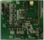
ADS8568EVM-PDK Evaluation Module
ABSTRACT
This user's guide describes the operation and use of the ADS8568 evaluation module (EVM). The ADS8568 is
an 8-channel, simultaneous sampling, 16-bit successive approximation (SAR) analog-to-digital converter (ADC).
Each input channel on the device can support true bipolar input ranges up to ±12 V. The device includes
a programmable internal buffered voltage reverence. The ADC includes a serial SPI interface and a parallel
interface for data communication. Configuration of the device is achieved through simple static digital input pins
(hardware mode) or through communications to the SPI interface. This user's guide covers circuit description,
schematic diagram, and bill of materials for the ADS8568 circuit board.
SBAU193E – JUNE 2011 – REVISED MAY 2021
Submit Document Feedback
ADS8568EVM-PDK Evaluation Module
Copyright © 2021 Texas Instruments Incorporated
1
�www.ti.com
Table of Contents
Table of Contents
1 EVM Overview......................................................................................................................................................................... 4
1.1 ADS8568EVM-PDK Kit Features....................................................................................................................................... 4
1.2 ADS8568EVM Board Features ......................................................................................................................................... 4
1.3 Related Documentation From Texas Instruments.............................................................................................................. 4
2 EVM Analog Interface.............................................................................................................................................................5
2.1 ADC Supply, Input, Voltage Reference, and Digital Connections...................................................................................... 5
2.2 ADC Amplifier Drive .......................................................................................................................................................... 6
3 Digital Interface.......................................................................................................................................................................7
3.1 Parallel Interface................................................................................................................................................................ 7
3.2 Serial Interface (SPI)..........................................................................................................................................................7
3.3 Connections to PHI connector........................................................................................................................................... 7
3.4 Static Signals for ADS8568................................................................................................................................................8
3.5 I2C Bus for Onboard EEPROM..........................................................................................................................................8
4 Power Supplies....................................................................................................................................................................... 9
4.1 Low Dropout Regulator...................................................................................................................................................... 9
4.2 Power Connections and LED Indicators............................................................................................................................ 9
5 Installing ADS8568EVM Software....................................................................................................................................... 10
6 ADS8568EVM Operation...................................................................................................................................................... 13
6.1 Connecting the Hardware and Running the GUI..............................................................................................................13
6.2 Jumper Settings for ADS8568EVM..................................................................................................................................14
6.3 EVM GUI Global Settings for ADC Control...................................................................................................................... 15
6.4 Time Domain Display....................................................................................................................................................... 16
6.5 Frequency Domain Display.............................................................................................................................................. 17
6.6 Histogram Display............................................................................................................................................................ 18
7 Modifying Hardware and Using Software to Evaluate ADS8548 and ADS8528.............................................................. 19
A Bill of Materials, Layout, and Schematic............................................................................................................................20
A.1 Bill of Materials................................................................................................................................................................ 20
A.2 Layout.............................................................................................................................................................................. 23
A.3 Schematic........................................................................................................................................................................ 26
B Revision History...................................................................................................................................................................29
List of Figures
Figure 1-1. System Connection for Evaluation............................................................................................................................ 4
Figure 2-1. ADC Signal and Supply Connection..........................................................................................................................5
Figure 2-2. Amplifier Drive Circuit................................................................................................................................................6
Figure 3-1. PHI to ADS8568EVM connector............................................................................................................................... 7
Figure 3-2. Static Digital Input Configuration............................................................................................................................... 8
Figure 3-3. EEPROM for EVM ID................................................................................................................................................ 8
Figure 4-1. Low Dropout Regulator for AVDD (5v Supply).......................................................................................................... 9
Figure 4-2. Supply Connections and Led Monitors......................................................................................................................9
Figure 5-1. ADS8568 Software Installation Prompts................................................................................................................. 10
Figure 5-2. Device Driver Installation Wizard Prompts.............................................................................................................. 11
Figure 5-3. LabVIEW Run-Time Engine Installation.................................................................................................................. 11
Figure 5-4. ADS8568EVM GUI Folder Post-Installation............................................................................................................ 12
Figure 6-1. ADS8568EVM Hardware Setup and LED Indicators...............................................................................................13
Figure 6-2. Launch the EVM GUI Software............................................................................................................................... 14
Figure 6-3. Global Settings for ADC Control..............................................................................................................................15
Figure 6-4. Time Domain Display.............................................................................................................................................. 16
Figure 6-5. Frequency Domain Display..................................................................................................................................... 17
Figure 6-6. Histogram Display................................................................................................................................................... 18
Figure 7-1. Enable EEPROM for Writing................................................................................................................................... 19
Figure 7-2. Configure EEPROM and Software for New Device.................................................................................................19
Figure A-1. Top and Bottom Layer ADS8568EVM.....................................................................................................................23
Figure A-2. Inner Power Layer...................................................................................................................................................24
Figure A-3. Inner Ground Layer.................................................................................................................................................25
Figure A-4. ADC schematic....................................................................................................................................................... 26
Figure A-5. ADC Drive Schematic............................................................................................................................................. 27
Figure A-6. Power and PHI Connections schmatic....................................................................................................................28
2
ADS8568EVM-PDK Evaluation Module
SBAU193E – JUNE 2011 – REVISED MAY 2021
Submit Document Feedback
Copyright © 2021 Texas Instruments Incorporated
�www.ti.com
Trademarks
List of Tables
Table 1-1. Related Documents.................................................................................................................................................... 4
Table 6-1. Jumper Settings........................................................................................................................................................ 14
Trademarks
All trademarks are the property of their respective owners.
SBAU193E – JUNE 2011 – REVISED MAY 2021
Submit Document Feedback
ADS8568EVM-PDK Evaluation Module
Copyright © 2021 Texas Instruments Incorporated
3
�EVM Overview
www.ti.com
1 EVM Overview
This document describes how to connect the EVM to your computer and test equipment to evaluate device
performance and understand device features. The document also describes how to install and use the
associated evaluation module software.
1.1 ADS8568EVM-PDK Kit Features
The ADS8568 evaluation module kit includes the following features:
•
•
•
•
Hardware and software required for diagnostic testing as well as accurate performance evaluation of the
ADS8568 ADC
Digital and analog interface power with USB power. External power required for high voltage ±15 V supply.
Easy-to-use evaluation software for 64-bit Microsoft Windows™7, Windows 8, and Windows 10 operating
systems.
PHI controller translates USB (2.0) or higher to parallel, or serial digital communications.
+/-15V
lab supply
Signal
Source
B0 A0
A0
ADS8568EVM
PHI Board
x
x
ADS8568
GUI
J9
B1
C1
Signal
Source
C0 D1
x
x
x
D0
Signal
Source
Included in kit
Figure 1-1. System Connection for Evaluation
1.2 ADS8568EVM Board Features
•
•
•
•
•
Eight input channels connected to external single ended signals source applied to SMA connectors or header
Serial and parallel interface connects to the PHI controller via 60 pin connector (J10)
High voltage power supplies (HVDD, and HVSS) are not included. Connect common lab supplies via terminal
strip J9.
Low voltage supplies (AVDD, and DVDD) generated using USB power from the PHI controller.
Integrated or external voltage reference options available.
1.3 Related Documentation From Texas Instruments
Related Documents lists devices that are used in this EVM and may be useful in related designs.
Table 1-1. Related Documents
4
Device
Literature Number
ADS8568
SBAS543
OPA2211
SBOS377
TPS7A4700
SLVS493
REF6025
SBOS708
ADS8568EVM-PDK Evaluation Module
SBAU193E – JUNE 2011 – REVISED MAY 2021
Submit Document Feedback
Copyright © 2021 Texas Instruments Incorporated
�www.ti.com
EVM Analog Interface
2 EVM Analog Interface
2.1 ADC Supply, Input, Voltage Reference, and Digital Connections
Figure 2-1 illustrates the decoupling on AVDD, DVDD, HVDD, HVSS, and the reference IO. The capacitors
for decoupling match the recommendations in the ADS8568 data sheet. The layout (see Figure 2-1) uses the
shortest possible connections to the decoupling capacitors and connections the ground end to the GND plane
using vias. The ADS8568 can use an external or internal voltage reference. This can be selected by changing
the position of JP9 to “INT” for internal, or “EXT” for external. Figure 2-1 also illustrates the analog input signal
and digital signal connections.
AVDD
U5
DVDD
C37
100nF
C38
100nF
C39
100nF
C40
100nF
C41
100nF
C42
100nF
50V
HVDD
GND
GND
25
R72
C43
10uF
GND
57
4
45
52
61
14
48
1.00
C44
100nF
50V
GND
A0
A1
42
47
B0
B1
49
54
64
59
C0
C1
7
2
D0
D1
R92
R93
R94
R96
CONVSTA
CONVSTB
CONVSTC
CONVSTD
49.9
49.9
49.9
49.9
37
38
39
40
C45
10uF
C46
10uF
50
53
C47
10uF
63
60
C48
10uF
6
3
43
46
GND
GND
GND
GND
56
55
C49
0.47uF
AVDD
AVDD
AVDD
AVDD
AVDD
AVDD
CS/FS
RD
ASLEEP
PAR/SER
DVDD
DB0/DCIN_D
DB1/DCIN_C
DB2/DCIN_B
DB3/DCIN_A
DB4
DB5/SEL_CD
DB6/SEL_B
DB7
DB8/DCEN
DB9/SDI
DB10/SCLK
DB11/REFBUFEN
DB12/SDO_A
DB13/SDO_B
DB14/SDO_C
DB15/SDO_D
HVDD
CH_A0
CH_A1
CH_B0
CH_B1
CH_C0
CH_C1
CH_D0
CH_D1
CONVST_A
CONVST_B
CONVST_C
CONVST_D
REFAP
REFAN
BUSY/INT
RANGE/XCLK
HW/SW
REFEN/WR
STBY
RESET
R65
R66
R67
R68
13
12
36
8
49.9
49.9
49.9
49.9
R70
R71
R73
R74
R75
R76
R79
R80
R81
R82
R83
R84
R85
R87
R88
R89
33
32
31
30
29
28
27
26
23
22
21
20
19
18
17
16
R95
R97
R98
R99
R100
R101
35
34
41
11
9
10
~CS_~FS
~RD
ASLEEP
~PAR_SER
49.9
49.9
49.9
49.9
49.9
49.9
49.9
49.9
49.9
49.9
49.9
49.9
49.9
49.9
49.9
49.9
49.9
49.9
49.9
49.9
49.9
49.9
EXT
AVDD
1
C52
100nF
C53
10uF
2
R108
GND
3
VIN
OUT_S
C54
10uF
0
RET_RD
DB0_DCIND
DB1_DCINC
DB2_DCINB
DB3_DCINA
DB4
DB5_SELCD
DB6_SELB
DB7
DB8_DCEN
DB9_SDI
DB10_SCLK
DB11_REFBUFEN
DB12_SDOA
DB13_SDOB
DB14_SDOC
DB15_SDOD
R86
0
RET_SCLK
BUSY
RANGE_XCLK
~HW_SW
REFEN_~WR
~STBY
RESET
REFBP
REFBN
REFCP
REFCN
REFDP
REFDN
AGND
AGND
AGND
AGND
AGND
AGND
REFIO
DGND
REFN
HVSS
44
51
58
62
15
5
24
GND
1
GND
ADS8568SPM
C50
100nF
GND
INT
EN
OUT_F
SS
GND_F
FILT
GND_S
TP4
5
R107
6
1.00
HVSS
C51
10uF
GND
GND
Vref
0
7
120k
4
R69
1
2
3
U6
~RD
RANGE_XCLK
~HW_SW
REFEN_~WR
~STBY
RESET
R104
JP9
~CS_~FS
ASLEEP
~PAR_SER
R109
0.22
8
REF6025IDGKR
GND
C55
22uF
GND
GND
Figure 2-1. ADC Signal and Supply Connection
SBAU193E – JUNE 2011 – REVISED MAY 2021
Submit Document Feedback
ADS8568EVM-PDK Evaluation Module
Copyright © 2021 Texas Instruments Incorporated
5
�EVM Analog Interface
www.ti.com
2.2 ADC Amplifier Drive
Figure 2-2 shows the op amp configuration for each ADC drive input. The default configuration is and inverting
configuration. This can be converted to a non-inverting configuration but uninstalling R6, and R14, and installing
R11. Also, R11 and C11 can be used to create a low pass filter. The jumper JP1 can be used to completely
bypass the amplifier. This diagram only shows one channel but this circuit is repeated 8 times. For other
channels, see Appendix A.
R3
DNP
0
C4
39pF
R4
1.00k
JP1
HVDD
Bypass
R6
1.00k
2
0
3
U1A
J1
R8
1
2
3
4
5
R11
0
DNP
R12
R14
0
C11 DNP
100nF
OPA2211AIDDA
9
4
1
A0
A0I
w/Amp
1
2
3
8
GND
10.0
A0
C12
2200pF
HVSS
GND
GND
GND
HVDD
GND
HVSS
HVDD
3
2
1
C1
100nF
50V
J9
HVSS
GND
HVDD
GND
C5
1uF
35V
C7
100nF
50V
HVSS
Figure 2-2. Amplifier Drive Circuit
6
ADS8568EVM-PDK Evaluation Module
SBAU193E – JUNE 2011 – REVISED MAY 2021
Submit Document Feedback
Copyright © 2021 Texas Instruments Incorporated
�Digital Interface
www.ti.com
3 Digital Interface
As noted in Section 1, the EVM interfaces with the PHI and communicates with the computer over the USB.
There are two devices on the EVM with which the PHI communicates: the ADS8568 ADC (over SPI) and the
EEPROM (over I2C). The EEPROM comes pre-programmed with the information required to configure and
initialize the ADS8568 platform. When the hardware is initialized, the EEPROM is no longer used.
3.1 Parallel Interface
The parallel interface signals are generated on the PHI controler and connected through J10. Each of these
signals has a 47-Ω resistor between the device and the controler to slow down the signal edges in order to
minimize signal overshoot. The digital signals can be monatored on J11 test header.
3.2 Serial Interface (SPI)
The ADS8568 ADC uses SPI serial communication in mode 2 (CPOL=1 and CPHA=0). Because the serial clock
(SCLK) frequency can be as fast as 45 MHz, the ADS8568EVM offers 47-Ω resistors between the controler
and device to aid with signal integrity. Typically, in high-speed SPI communication, fast signal edges can cause
overshoot; these 47-Ω resistors slow down the signal edges in order to minimize signal overshoot.
3.3 Connections to PHI connector
Connector J10 is used to connect the PHI digital controller PCB to the ADS8568EVM. This connector has all the
digital signals as well as the 5.5V regulated supply and the DVDD supply. The power for the two supplies is from
the USB connection. The 5.5V supply is used to generate the AVDD supply. This connector also provides I2C
signals that are used on the EEPROM identification circuit.
TP2
J10
2
4
6
8
10
12
14
16
18
20
22
24
26
28
30
32
34
36
38
40
42
44
46
48
50
52
54
EVM_ID_SDA 56
EVM_ID_SCL 58
60
ASLEEP
~HW_SW
CONVSTD
CONVSTC
CONVSTB
CONVSTA
~CS_~FS
~RD
RET_RD
BUSY
REFEN_~WR
TP1
DVDD
R113 5.11
DVDD
~PAR_SER
RANGE_XCLK
RESET1
~STBY
C61
10uF
D5
5V
2
4
6
8
10
12
14
16
18
20
22
24
26
28
30
32
34
36
38
40
42
44
46
48
50
52
54
56
58
60
MP1
MP2
GND
GND
GND
GND
5.5V
1
3
5
7
9
11
13
15
17
19
21
23
25
27
29
31
33
35
37
39
41
43
45
47
49
51
53
55
57
59
1
3
5
7
9
11
13
15
17
19
21
23
25
27
29
31
33
35
37
39
41
43
45
47
49
51
53
55
57
59
GND
GND
DB0_DCIND
DB1_DCINC
DB2_DCINB
DB3_DCINA
DB4
DB5_SELCD
DB6_SELB
DB7
DB8_DCEN
DB9_SDI
DB10_SCLK
DB11_REFBUFEN
DB12_SDOA
DB13_SDOB
DB14_SDOC
DB15_SDOD
RET_SCLK
GND
EVM_ID_WP
ID_PWR
ID_PWR
MP3
MP4
QTH-030-01-L-D-A
GND
GND
J11
CONVST_D
CONVST_B
ASLEEP
RANGE/XCLK
DB1/DCIN_C
DB3/DCIN_A
DB5/SEL_CD
DB7
DB9/SDI
DB11/REFBUFEN
DB13/SDO_B
DB15/SDO_D
~CS/~FS
REFEN/~WR
~STBY
1
3
5
7
9
11
13
15
17
19
21
23
25
27
29
31
CONVSTD
CONVSTB
ASLEEP
RANGE_XCLK
DB1_DCINC
DB3_DCINA
DB5_SELCD
DB7
DB9_SDI
DB11_REFBUFEN
DB13_SDOB
DB15_SDOD
~CS_~FS
REFEN_~WR
~STBY
2
4
6
8
10
12
14
16
18
20
22
24
26
28
30
32
~HW_SW
CONVSTC
CONVSTA
BUSY
DB0_DCIND
DB2_DCINB
DB4
DB6_SELB
DB8_DCEN
DB10_SCLK
DB12_SDOA
DB14_SDOC
~RD
RESET1
~PAR_SER
~HW/SW
CONVST_C
CONVST_A
BUSY
DB0/DCIN_D
DB2/DCIN_B
DB4
DB6/SEL_B
DB8/DCEN
DB10/SCLK
DB12/SDO_A
DB14/SDO_C
~RD
RESET
~PAR/SER
TSW-116-07-G-D
GND
GND
Figure 3-1. PHI to ADS8568EVM connector
SBAU193E – JUNE 2011 – REVISED MAY 2021
Submit Document Feedback
ADS8568EVM-PDK Evaluation Module
Copyright © 2021 Texas Instruments Incorporated
7
�www.ti.com
Digital Interface
3.4 Static Signals for ADS8568
The ADS8568 has several static digital configuration pins. The logic state of the pin will determine the operation
of the device. For example, the PAR/SER digital pin will determine if the communication is in parallel or serial
mode. These pins are automatically controlled by the PHI digital controller when the GUI is in "hardware mode".
The logic level on these pins can be monitored using test points on J11 or as shown in Figure 3-2. Some
of these digital control pins also have resistors that can be used to configure the logic levels when the PHI
controller is not used. Figure 3-2 shows the static logic configuration. To set a pin to logic high the resistor
connected to DVDD is installed. To set an input to logic low the resistor connected to GND needs to be installed.
It is important to understand that the configuration of these resistors does not matter when the PHI is used as
it will drive the logic level to whatever the GUI setting is. These digital input configuration resistors only matter
when the EVM is disconnect from the PHI and used with a different digital controller.
Figure 3-2 also shows the operation of the reset control line. This reset can be initiated by the PHI controller or
by the push button switch. Note that RESET is an active high signal so the two reset signals are applied to an
OR function so that the device will be reset if either the push button is pressed or the PHI drives the signal active
high.
DVDD
DVDD
TP8
TP9
~HW_SW
~PAR_SER
~HW_SW
DVDD
R59
DNP
10.0k
NORM
R78
DNP
10.0k
ASLEEP
SER
SW
DVDD
R77
DNP
10.0k
TP12
R61
10.0k
R91
10.0k
~STBY
~STBY
R90
10.0k
NORM
~PAR
ASLEEP
~HW
TP13
~STBY
ASLEEP
~PAR_SER
R62
10.0k
GND
GND
R64
DNP
10.0k
GND
GND
DVDD
R102
DNP
10.0k
INT
R110
10.0k
R103
10.0k
TP10
TP11
RANGE_XCLK
RESET1
2
2Vref
HIGH
DVDD
DVDD
REFEN_~WR
U9A
RANGE_XCLK
REFEN_~WR
S1
1
1
4
RESET
R105
10.0k
GND
SN74AHC1G32DRLR
LOW
EXT
4Vref
2
R106
DNP
10.0k
GND
C56
1000pF
GND
R111
10.0k
GND
Figure 3-2. Static Digital Input Configuration
3.5 I2C Bus for Onboard EEPROM
The circuit shown in Figure 3-3 is used with our EVM controler (PHI), for EVM identification. This circuit is not
required by the ADS8568 for operation. The switch (S2) is a write protect and does not need to be changed for
EVM operation.
ID_PWR
R112
10.0k
C59
100nF
S2
U7
1
2
GND
3
4
A0
VCC
A1
WP
A2
SCL
VSS
SDA
8
1
7
EVM_ID_WP
2
6
EVM_ID_SCL
3
5
EVM_ID_SDA
GND
BR24G32FVT-3AGE2
C60
100nF
GND
GND
Figure 3-3. EEPROM for EVM ID
8
ADS8568EVM-PDK Evaluation Module
SBAU193E – JUNE 2011 – REVISED MAY 2021
Submit Document Feedback
Copyright © 2021 Texas Instruments Incorporated
�Power Supplies
www.ti.com
4 Power Supplies
The ADS8568EVM has four power supplies: AVDD (5 V), DVDD (3.3 V), HVDD (15 V), and HVSS (-15 V).
The two high voltage power supplies require an external ±15 V supply and are connected on a screw terminal
strip (J9). The lower voltage supplies (AVDD and DVDD), are generated with the USB power and low dropout
regulators (LDO).
4.1 Low Dropout Regulator
U8 is a low dropout regulator (LDO) used to convert the 5.5 V regulated supply from the PHI to a low noise 5 V
supply. The input and output of this LDO can be monitored on TP2 and TP3.
TP3
U8
HVDD
R114
15
16
IN
IN
13
EN
AVDD
OUT
OUT
SENSE
3
C63
10uF
100k
C62
22uF
4
5
6
8
9
10
11
12
GND
R115
0
R116
0
6P4V2
6P4V1
3P2V
1P6V
0P8V
0P4V
0P2V
0P1V
AVDD
1
20
NR
14
NC
NC
NC
NC
19
18
17
2
GND
PAD
7
21
C64
1uF
GND
GND
TPS7A4700RGWR
GND
GND
Figure 4-1. Low Dropout Regulator for AVDD (5v Supply)
4.2 Power Connections and LED Indicators
The screw terminal block J9 is used to connect the external high voltage supplies. These supplies are not
provided in the evaluation module kit and it is expected that you will use low noise lab supply to provide this
power (for example, Keysight E3632a). The high voltage supplies have transient voltage suppressor diodes to
help protect the ADC from transients. These supplies are typically connected to +/-15 V. For details on operation,
see the ADS8568 data sheet. Figure 4-2 also shows how each supply has an LED monitor for quick verification
that power is applied.
DVDD
HVSS
R44
20.0k
1
D4
Green
D6
Green
2
2
GND
R113
GND
GND
5.11
R118
6.65k
C61
10uF
1
R117
6.65k
1
D3
Green
TP1
DVDD
DVDD
2
1
R43
20.0k
AVDD
D5
5V
D7
Green
2
HVDD
GND
GND
GND
GND
HVSS
D1
15V
HVSS
D2
15V
HVDD
3
2
1
HVDD
GND
HVSS
GND
HVDD
J9
GND
Figure 4-2. Supply Connections and Led Monitors
SBAU193E – JUNE 2011 – REVISED MAY 2021
Submit Document Feedback
ADS8568EVM-PDK Evaluation Module
Copyright © 2021 Texas Instruments Incorporated
9
�www.ti.com
Installing ADS8568EVM Software
5 Installing ADS8568EVM Software
Download the latest version of the EVM GUI installer from the Tools and Software folder of the ADS8568EVM
and run the GUI installer to install the EVM GUI software on your computer.
CAUTION
Manually disable any anti-virus software running on the computer before downloading the EVM GUI
installer onto the local hard disk. Depending on the anti-virus settings, an error message may appear
or the installer. The exe file can be deleted.
Accept the license agreements and follow the on-screen instructions shown in Figure 5-1 to complete the
installation.
Figure 5-1. ADS8568 Software Installation Prompts
As a part of the ADS8568EVM GUI installation, a prompt with a Device Driver Installation (as shown in Figure
5-2) appears on the screen. Click Next to proceed.
10
ADS8568EVM-PDK Evaluation Module
SBAU193E – JUNE 2011 – REVISED MAY 2021
Submit Document Feedback
Copyright © 2021 Texas Instruments Incorporated
�Installing ADS8568EVM Software
www.ti.com
Figure 5-2. Device Driver Installation Wizard Prompts
The ADS8568EVM requires the LabVIEW™ run-time engine and may prompt for the installation of this software,
as shown in Figure 5-3, if not already installed.
Figure 5-3. LabVIEW Run-Time Engine Installation
Verify that C:\Program Files (x86)\Texas Instruments\ADS8568EVM is as shown in Figure 5-4 after these
installations.
SBAU193E – JUNE 2011 – REVISED MAY 2021
Submit Document Feedback
ADS8568EVM-PDK Evaluation Module
Copyright © 2021 Texas Instruments Incorporated
11
�Installing ADS8568EVM Software
www.ti.com
Figure 5-4. ADS8568EVM GUI Folder Post-Installation
12
ADS8568EVM-PDK Evaluation Module
SBAU193E – JUNE 2011 – REVISED MAY 2021
Submit Document Feedback
Copyright © 2021 Texas Instruments Incorporated
�www.ti.com
ADS8568EVM Operation
6 ADS8568EVM Operation
The following instructions are a step-by-step guide to connecting the ADS8568EVM to the computer and
evaluating the performance of the ADS8568:
6.1 Connecting the Hardware and Running the GUI
1. Set the jumpers according to Table 6-1.
2. Physically connect P2 of the PHI to J10 of the ADS8568EVM. Install the screws to assure a robust
connection.
3. Connect USB on PHI to the computer first.
a. LED D5 on the PHI lights up, indicating that the PHI is powered up.
b. LEDs D1 and D2 on the PHI start blinking to indicate that the PHI is booted up and communicating with
the PC; Figure 6-1 shows the resulting LED indicators.
4. Start the software GUI as shown in Figure 6-2. You will notice that the LEDs blink slowly as the FPGA
firmware is loaded on the PHI. This will take a few seconds then the AVDD and DVDD power supplies will
turn on.
5. Connect the high voltage power supplies (HVDD = +15 V, HVSS = -15 V, and GND).
6. Connect the signal generator. The default input range is ±10 V (or 10Vpk). A common input signal applied is
a sinusoidal 1kHz, 9.9Vpk signal with a 0 V offset. Note that this signal is adjusted just below the full scale
range to avoid clipping.
HVSS
-15V
GND
HVDD
+15V
5. Apply high voltage power supplies using
external DC lab supply (not provided).
HVDD = +15V, HVSS = -15V, and GND = 0V.
HVSS
GND
HVDD
2. Connect PHI to ADS8568EVM
and install screws.
6. Apply input signals.
Input range = ±10V in the
default configuration.
Connect the eight input
channels as desired.
D5
ADS8568EVM
PHI
D2
D1
3. Connect USB power before
applying signal source.
4. Start the software GUI.
1. Set jumpers according to
your requirements. Review
Table 6-1 for details.
Figure 6-1. ADS8568EVM Hardware Setup and LED Indicators
SBAU193E – JUNE 2011 – REVISED MAY 2021
Submit Document Feedback
ADS8568EVM-PDK Evaluation Module
Copyright © 2021 Texas Instruments Incorporated
13
�ADS8568EVM Operation
www.ti.com
Figure 6-2 shows how the software can be started on the start menu or using a desktop icon.
Select EVM GUI
from start menu,
or associated
shortcut
Figure 6-2. Launch the EVM GUI Software
6.2 Jumper Settings for ADS8568EVM
The amplifiers and reference can be configured with jumpers. The amplifier jumpers (JP1-JP8) determine if the
amplifier is used or if an external signal is directly connected to the ADC input. JP9 is used to select either the
internal reference option or external reference option. Take care to make sure that the GUI configuration for the
device reference matches the setting of JP9. The GUI software starts up in the "internal" reference mode, so
make sure the JP9 is in the "INT" position.
Table 6-1. Jumper Settings
Jumper
Setting
Default
Function
JP1 to JP8
wAmp / Bypass
wAmp
These eight jumpers determine if the amplifier is used to buffer the inputs signals or if it
is bypassed. Choosing wAmp will connect the amplifier between each SMA connector
(J1 to J8) and the ADC input. The default amplifier configuration is inverting (Gain =
-1V/V). The amplifier gain configuration can be adjusted by soldering and de-soldering
different resistors. Choosing the Bypass configuration will connect the SMA connectors
directly to the ADC input.
JP9
EXT / INT
INT
This jumper will select internal vs external mode on the voltage reference. Using
internal mode will disconnect the external reference. Using external mode will connect
the external REF6025 2.5 V reference to the ADC reference input. Take care to make
sure that the GUI settings for the voltage reference match this jumpers setting.
14
ADS8568EVM-PDK Evaluation Module
SBAU193E – JUNE 2011 – REVISED MAY 2021
Submit Document Feedback
Copyright © 2021 Texas Instruments Incorporated
�www.ti.com
ADS8568EVM Operation
6.3 EVM GUI Global Settings for ADC Control
Figure 6-3 shows that the EVM Global controls are located on the right hand side of the GUI. These controls
choose the page display, SPI Mode, SCLK frequency, and sampling frequency.
Pages selects the
analysis display.
Toggles Reset pin on
ADC.
This device can use different input
voltage ranges, serial or parallel
communications, hardware or
software mode, and internal or
external reference. Refer to the
data sheet for details on these
modes.
The maximum clock is 45MHz and
the maximum sampling rate is
494.5kHz for this device.
Figure 6-3. Global Settings for ADC Control
SBAU193E – JUNE 2011 – REVISED MAY 2021
Submit Document Feedback
ADS8568EVM-PDK Evaluation Module
Copyright © 2021 Texas Instruments Incorporated
15
�ADS8568EVM Operation
www.ti.com
6.4 Time Domain Display
The time domain display tool allows visualization of the ADC response to a given input signal. This tool is useful
for both studying the behavior and debugging any gross problems with the ADC or drive circuits.
The user can trigger a capture of the data of the selected number of samples from the ADS8568EVM, as per the
current interface mode settings indicated in Figure 6-4 by using the Capture button. The sample indices are on
the x-axis and there are two y-axes showing the corresponding output codes as well as the equivalent analog
voltages based on the specified reference voltage. Switching pages to any of the Analysis tools described in the
subsequent sections causes calculations to be performed on the same set of data.
Figure 6-4. Time Domain Display
16
ADS8568EVM-PDK Evaluation Module
SBAU193E – JUNE 2011 – REVISED MAY 2021
Submit Document Feedback
Copyright © 2021 Texas Instruments Incorporated
�www.ti.com
ADS8568EVM Operation
6.5 Frequency Domain Display
The spectral analysis tool, shown in Figure 6-5, is intended to evaluate the dynamic performance (SNR, THD,
SFDR, SINAD, and ENOB) of the ADS8568 ADC through single-tone sinusoidal signal FFT analysis using the 7term Blackman-Harris window setting. The FFT tool includes windowing options that are required to mitigate the
effects of non-coherent sampling (this discussion is beyond the scope of this document). The 7-Term Blackman
Harris window is the default option and has sufficient dynamic range to resolve the frequency components of up
to a 24-bit ADC. The None option corresponds to not using a window (or using a rectangular window) and is not
recommended.
Figure 6-5. Frequency Domain Display
SBAU193E – JUNE 2011 – REVISED MAY 2021
Submit Document Feedback
ADS8568EVM-PDK Evaluation Module
Copyright © 2021 Texas Instruments Incorporated
17
�ADS8568EVM Operation
www.ti.com
6.6 Histogram Display
Noise degrades ADC resolution and the histogram tool can be used to estimate effective resolution, which
is an indicator of the number of bits of ADC resolution losses resulting from noise generated by the various
sources connected to the ADC when measuring a DC signal. The cumulative effect of noise coupling to the
ADC output from sources such as the input drive circuits, the reference drive circuit, the ADC power supply,
and the ADC itself is reflected in the standard deviation of the ADC output code histogram that is obtained by
performing multiple conversions of a DC input applied to a given channel. As shown in Figure 6-6, the histogram
corresponding to a DC input is displayed on clicking the Capture button.
Figure 6-6. Histogram Display
18
ADS8568EVM-PDK Evaluation Module
SBAU193E – JUNE 2011 – REVISED MAY 2021
Submit Document Feedback
Copyright © 2021 Texas Instruments Incorporated
�Modifying Hardware and Using Software to Evaluate ADS8548 and ADS8528
www.ti.com
7 Modifying Hardware and Using Software to Evaluate ADS8548 and ADS8528
The ADS8568 is part of a family of related devices. This EVM hardware and software will support the entire
family as all the devices are pin-for-pin compatable. The ADS8548 is the 14 bit version of the device, and the
ADS8528 is the 12 bit version of the device. The procedure below shows how to modify the hardware and
software to evaluate the other devices in this family.
1. Desolder the ADS8568 device an replace it with the device you want to evaluate.
2. Enable the EEPROM for writing. This is done by changing switch S2 to the top position using tweezers. For
details, see Figure 7-1.
3. Connect EVM and start GUI as described in Connecting the Hardware and Running the GUI.
4. Use the "Tools" menu to "Load EEPROM" according to the device that is currently installed. When this
procedure is successfully completed, you will see the status bar at the top of the software update according
to the device installed on the hardware. For details, see Figure 7-2.
Use tweezers to change position of
Switch S2 to up as shown to allow
the EEPROM write operation.
Figure 7-1. Enable EEPROM for Writing
1. Kv šZ ^d}}o•_ u vµ
• o š ^>}
WZKD_
3. (š Œ ‰Œ ••]vP ^o}
WZKD_ ]š Á]oo š l ( Á
minutes to load the EEPROM.
2. hv Œ ^^µ‰‰}Œš
À] •_
select the desired device and
‰Œ •• ^>}
WZKD_
4. The top of status bar on the
software will indicate what the EVM
Connected has been updated to.
Figure 7-2. Configure EEPROM and Software for New Device
SBAU193E – JUNE 2011 – REVISED MAY 2021
Submit Document Feedback
ADS8568EVM-PDK Evaluation Module
Copyright © 2021 Texas Instruments Incorporated
19
�Bill of Materials, Layout, and Schematic
www.ti.com
A Bill of Materials, Layout, and Schematic
Schematics for the ADS8568EVM are appended to this user's guide. The bill of materials is provided in Bill of
Materials. Layout shows the PCB layouts for the ADS8568EVM.
A.1 Bill of Materials
Designator
Qty
Value
Description
Part Number
!PCB1
1
C1, C2, C7, C8, C13, C14,
C17, C18, C37, C38, C39,
C40, C41, C42, C44, C50,
C52, C59, C60, C65
20
0.1 μF
CAP, CERM, 0.1 μF, 50 V, ±
10%, X7R, 0603
C3, C4, C19, C20, C25,
C26, C31, C32
8
39 pF
CAP, CERM, 39 pF, 50 V, ± 5%,
C0G/NP0, 0603
CGA3E2C0G1H390J080AA
C5, C6, C15, C16, C64
5
1 μF
CAP, CERM, 1 μF, 35 V, ± 10%,
X5R, 0603
GMK107BJ105KA-T
C10, C12, C22, C24, C28,
C30, C34, C36
8
C43, C45, C46, C47, C48,
C51, C53, C54, C61, C63
10
10uF
C49
1
C55, C62
2
C56
1
D1, D2
2
15 V
D3, D4, D6, D7
4
Green
D5
1
5V
H1, H2, H3, H4
4
Hex Standoff Threaded #4-40
Aluminum 0.250" (6.35mm) 1/4"
H5, H6, H7, H8
4
MACHINE SCREW PAN
PHILLIPS 4-40
H9, H10
2
ROUND STANDOFF M3 STEEL
5MM
H11, H12
2
H13
Printed Circuit Board
2200 pF CAP, CERM, 2200 pF, 50 V, ±
5%, C0G/NP0, 0603
DC121
C0603C104K5RACTU
Manufacturer
Any
Kemet
TDK Corporation
Taiyo Yuden
GRM1885C1H222JA01D
MuRata
CAP, CERM, 10 μF, 35 V, ±
10%, X5R, 0805
C2012X5R1V106K125AC
TDK
0.47 μF
CAP, CERM, 0.47 μF, 50 V, ±
10%, X5R, 0603
C1608X5R1H474K080AB
TDK
22 μF
CAP, CERM, 22 uF, 35 V, +/20%, X5R, 0805
C2012X5R1V226M125AC
TDK
06035A102KAT2A
AVX
1000 pF CAP, CERM, 1000 pF, 50 V, ±
10%, C0G/NP0, 0603
Diode, TVS, Uni, 15 V, 24.4 Vc,
SMB
LED, Green, SMD
Diode, TVS, Uni, 5 V, 9.2 Vc,
400 W, 43.5 A, SMA
SMBJ15A-13-F
Diodes Inc.
APT2012LZGCK
Kingbright
SMAJ5.0A
Littelfuse
1891
Keystone
PMSSS 440 0025 PH
B&F Fastener
Supply
9774050360R
Wurth Elektronik
Machine Screw Pan PHILLIPS
M3
RM3X4MM 2701
APM HEXSEAL
1
Cable, USB-A to micro USB-B,
1 m - Kitting item
102-1092-BL-00100
H14
1
PHI-EVM Controller Kitting item
Edge# 6591636
PA007
Texas Instruments
J1, J2, J3, J4, J5, J6, J7,
J8
8
Connector, SMA, TH
142-0701-201
Cinch Connectivity
J9
1
Terminal Block, 3.5 mm, 3x1,
Tin, TH
0393570003
J10
1
Header(Shrouded), 19.7 mil,
30x2, Gold, SMT
QTH-030-01-L-D-A
Samtec
J11
1
Header, 100 mil, 16x2, Gold, TH
TSW-116-07-G-D
Samtec
JP1, JP2, JP3, JP4, JP5,
JP6, JP7, JP8, JP9
9
Header, 100 mil, 3x1, Gold, TH
TSW-103-07-G-S
Samtec
LBL1
1
Thermal Transfer Printable
Labels, 0.650" W x 0.200" H 10,000 per roll
20
ADS8568EVM-PDK Evaluation Module
THT-14-423-10
CnC Tech
Molex
Brady
SBAU193E – JUNE 2011 – REVISED MAY 2021
Submit Document Feedback
Copyright © 2021 Texas Instruments Incorporated
�www.ti.com
Bill of Materials, Layout, and Schematic
Designator
Qty
Value
Description
R2, R4, R5, R6, R16, R18,
R19, R20, R30, R32, R33,
R34, R46, R48, R49, R50
16
1.00k
RES, 1.00 k, 1%, 0.1 W, 0603
R7, R8, R21, R22, R35,
R36, R51, R52
8
10.0
R10, R12, R13, R14, R24,
R26, R27, R28, R38, R40,
R41, R42, R54, R56, R57,
R58, R69, R86, R107,
R115, R116
21
R43, R44
R61, R62, R90, R91,
R103, R105, R110, R111,
R112
Part Number
Manufacturer
RC0603FR-071KL
Yageo
RES, 10.0, 1%, 0.1 W, 0603
RC0603FR-0710RL
Yageo
0
RES, 0, 1%, 0.1 W, AEC-Q200
Grade 0, 0603
RMCF0603ZT0R00
Stackpole
Electronics Inc
2
20.0k
RES, 20.0 k, 1%, 0.1 W, 0603
RC0603FR-0720KL
Yageo
9
10.0k
RES, 10.0 k, 1%, 0.1 W, AECQ200 Grade 0, 0603
RMCF0603FT10K0
Stackpole
Electronics Inc
R65, R66, R67, R68, R70,
R71, R73, R74, R75, R76,
R79, R80, R81, R82, R83,
R84, R85, R87, R88, R89,
R92, R93, R94, R95, R96,
R97, R98, R99, R100,
R101
30
49.9
RES, 49.9, 1%, 0.1 W, 0603
RC0603FR-0749R9L
Yageo
R72, R104
2
1.00
RES, 1.00, 1%, 0.1 W, 0603
RC0603FR-071RL
Yageo
R108
1
120k
RES, 120 k, 1%, 0.1 W, 0603
RC0603FR-07120KL
R109
1
0.22
RES, 0.22, 1%, 0.1 W, AECQ200 Grade 0, 0603
ERJ-3RQFR22V
R113
1
5.11
RES, 5.11, 1%, 0.1 W, AECQ200 Grade 0, 0603
CRCW06035R11FKEA
R114
1
100k
RES, 100 k, 1%, 0.1 W, 0603
RC0603FR-07100KL
Yageo
R117, R118
2
6.65k
RES, 6.65 k, 1%, 0.1 W, 0603
RC0603FR-076K65L
Yageo
S1
1
Switch, Tactile, SPST-NO,
0.05A, 12V, SMD
S2
1
Switch, Slide, SPDT 100 mA,
SMT
CAS-120TA
Copal Electronics
SH-J1, SH-J2, SH-J3, SHJ4, SH-J5, SH-J6, SH-J7,
SH-J8, SH-J9
9
Shunt, 100 mil, Flash Gold,
Black
SPC02SYAN
Sullins Connector
Solutions
TP1, TP2, TP3, TP4, TP6,
TP7, TP8, TP9, TP10,
TP11, TP12, TP13
12
Test Point, Multipurpose, Red,
TH
5010
Keystone
TP5, TP14
2
Test Point, Multipurpose, Black,
TH
5011
Keystone
U1, U2, U3, U4
4
1.1 nV/rtHz Noise, Low Power,
Precision Operational Amplifier,
4.5 to 36 V, -40 to 125 degC, 8pin SOP (DDA8), Green (RoHS
& no Sb/Br)
OPA2211AIDDA
Texas Instruments
U5
1
Analog to Digital Converters
- ADC 16B,8Ch,Sim Sampling
Bipolar Inp ADC
ADS8568SPM
Texas Instruments
U6
1
5ppm/C High-Precision Voltage
Reference with Integrated HighBandwidth Buffer, DGK0008A
(VSSOP-8)
REF6025IDGKR
Texas Instruments
U7
1
I2C BUS EEPROM (2-Wire),
TSSOP-B8
U8
1
36V, 1A, 4.17μVRMS,
RF Low-Dropout (LDO)
Voltage Regulator, RGW0020A
(VQFN-20)
1x2
SBAU193E – JUNE 2011 – REVISED MAY 2021
Submit Document Feedback
EVQPNF04M
BR24G32FVT-3AGE2
TPS7A4700RGWR
Yageo
Panasonic
Vishay-Dale
Panasonic
Rohm
Texas Instruments
ADS8568EVM-PDK Evaluation Module
Copyright © 2021 Texas Instruments Incorporated
21
�Bill of Materials, Layout, and Schematic
Designator
Qty
www.ti.com
Value
U9
1
C9, C11, C21, C23, C27,
C29, C33, C35
0
FID1, FID2, FID3
0
R1, R3, R9, R11, R15,
R17, R23, R25, R29, R31,
R37, R39, R45, R47, R53,
R55
0
0
R59, R64
0
10.0k
R77, R78, R102, R106
0
10.0k
22
Description
Part Number
Single 2-Input Positive-OR
Gate, DRL0005A, LARGE T&R
0.1uF
CAP, CERM, 0.1 μF, 50 V, ±
10%, X7R, 0603
SN74AHC1G32DRLR
GRM188R71H104KA93D
Fiducial mark. There is nothing
to buy or mount.
RES, 0, 5%, 0.1 W, 0603
N/A
Manufacturer
Texas Instruments
MuRata
N/A
RC0603JR-070RL
Yageo
RES, 10.0 k, 1%, 0.1 W, 0603
RC0603FR-0710KL
Yageo
RES, 10.0 k, 1%, 0.1 W, AECQ200 Grade 0, 0603
RMCF0603FT10K0
Stackpole
Electronics Inc
ADS8568EVM-PDK Evaluation Module
SBAU193E – JUNE 2011 – REVISED MAY 2021
Submit Document Feedback
Copyright © 2021 Texas Instruments Incorporated
�www.ti.com
Bill of Materials, Layout, and Schematic
A.2 Layout
Top and Bottom Layer ADS8568EVM shows the top and bottom layers. All signals are on top and bottom.
TOP
BOTTOM
Figure A-1. Top and Bottom Layer ADS8568EVM
SBAU193E – JUNE 2011 – REVISED MAY 2021
Submit Document Feedback
ADS8568EVM-PDK Evaluation Module
Copyright © 2021 Texas Instruments Incorporated
23
�Bill of Materials, Layout, and Schematic
www.ti.com
DVDD
AVDD
HVDD
HVSS
Inner Power Layer shows all power supply connections (AVDD, DVDD, HVDD, and HVSS).
Figure A-2. Inner Power Layer
Inner Ground Layer shows the internal ground layer. All GND connections are to this layer using vias.
24
ADS8568EVM-PDK Evaluation Module
SBAU193E – JUNE 2011 – REVISED MAY 2021
Submit Document Feedback
Copyright © 2021 Texas Instruments Incorporated
�www.ti.com
Bill of Materials, Layout, and Schematic
Figure A-3. Inner Ground Layer
SBAU193E – JUNE 2011 – REVISED MAY 2021
Submit Document Feedback
ADS8568EVM-PDK Evaluation Module
Copyright © 2021 Texas Instruments Incorporated
25
�A
B
C
D
1
1
DVDD
R59
DNP
10.0k
ASLEEP
R62
10.0k
GND
ASLEEP
RANGE_XCLK
~HW_SW
TP12
TP8
TP11
DVDD
R61
10.0k
~STBY
R64
DNP
10.0k
GND
R106
DNP
10.0k
GND
U9A
2
C53
10uF
REFEN_~WR
~PAR_SER
TP13
~STBY
TP9
TP10
RESET
C52
100nF
AVDD
GND
SN74AHC1G32DRLR
4
REFEN_~WR
R103
10.0k
DVDD
GND
R91
10.0k
~PAR_SER
R78
DNP
10.0k
DVDD
1
2
R108
120k
C54
10uF
GND
C65
100nF
DVDD
GND
HVDD
C43
10uF
GND
3
R72
VIN
GND_F
OUT_F
OUT_S
1.00
EN
GND_S
U6
FILT
3
SS
REF6025IDGKR
GND
SN74AHC1G32DRLR
VCC
U9B
1
2
3
4
5
GND
3
5
6
7
8
DVDD
C42
100nF
50V
C44
100nF
50V
GND
GND
GND
AVDD
C37
100nF
A0
A1
B0
B1
C0
C1
D0
D1
0
CONVSTA
CONVSTB
CONVSTC
CONVSTD
R107
R109
0.22
C55
22uF
GND
JP9
4
C41
100nF
48
25
57
4
45
52
61
14
42
47
49
54
7
2
64
59
10uF
50
53
43
46
37
38
39
40
10uF
6
3
63
60
C46
10uF
55
56
10uF
C49
0.47uF
C47
GND
TP4
Vref
C48
C45
49.9
49.9
49.9
49.9
C40
100nF
R92
R93
R94
R96
INT
C39
100nF
GND
GND
GND
GND
GND
C38
100nF
EXT
4
U5
DVDD
AVDD
AVDD
AVDD
AVDD
AVDD
AVDD
CH_A0
CH_A1
HVDD
CH_B0
CH_B1
CH_D0
CH_D1
CH_C0
CH_C1
CONVST_A
CONVST_B
CONVST_C
CONVST_D
REFAP
REFAN
REFBP
REFBN
REFCP
REFCN
5
CS/FS
RD
ASLEEP
PAR/SER
DB0/DCIN_D
DB1/DCIN_C
DB2/DCIN_B
DB3/DCIN_A
DB4
DB5/SEL_CD
DB6/SEL_B
DB7
DB8/DCEN
DB9/SDI
DB10/SCLK
DB11/REFBUFEN
DB12/SDO_A
DB13/SDO_B
DB14/SDO_C
DB15/SDO_D
BUSY/INT
RANGE/XCLK
HW/SW
REFEN/WR
STBY
RESET
AGND
AGND
AGND
AGND
AGND
AGND
DGND
REFDP
REFDN
REFIO
HVSS
5
Orderable:
ADS8568BEVM-PDK
TID #:
N/A
Number: DC121
Rev: B
SVN Rev:
Not in version control
Drawn By: Sima Jalaleddine
Engineer: Arthur Kay
ADS8568SPM
REFN
Texas Instruments and/or its licensors do not warrant the accuracy or completeness of this specification or any information contained therein. Texas Instruments and/or its licensors do not
warrant that this design will meet the specifications, will be suitable for your application or fit for any particular purpose, or will operate in an implementation. Texas Instruments and/or its
licensors do not warrant that the design is production worthy. You should completely validate and test your design implementation to confirm the system functionality for your application.
13
12
36
8
33
32
31
30
29
28
27
26
23
22
21
20
19
18
17
16
35
34
41
11
9
10
44
51
58
62
15
5
24
1
R65
R66
R67
R68
R95
R97
R98
R99
R100
R101
49.9
49.9
49.9
49.9
~CS_~FS
ASLEEP
~PAR_SER
R69
R86
1/7/2021
0
6
6
Sheet: 2 of 4
Size: B
Mod. Date:
BUSY
RANGE_XCLK
~HW_SW
REFEN_~WR
~STBY
RESET
DB11_REFBUFEN
DB12_SDOA
DB13_SDOB
DB14_SDOC
DB15_SDOD
DB0_DCIND
DB1_DCINC
DB2_DCINB
DB3_DCINA
DB4
DB5_SELCD
DB6_SELB
DB7
DB8_DCEN
DB9_SDI
~CS_~FS
~RD
ASLEEP
~PAR_SER
49.9
49.9
49.9
49.9
49.9
49.9
49.9
49.9
49.9
49.9
49.9
49.9
49.9
49.9
49.9
49.9
GND
C51
10uF
HVSS
GND
RANGE_XCLK
~HW_SW
REFEN_~WR
~STBY
RESET
1.00
R104
GND
C50
100nF
49.9
49.9
49.9
49.9
49.9
49.9
R70
R71
R73
R74
R75
R76
R79
R80
R81
R82
R83
R84
R85
R87
R88
R89
GND
Designed for: Public Release
Project Title:
ADS8568BEVM-PDK
Sheet Title:
Assembly Variant: 001
File:
DC121B_Schematic2.SchDoc
Contact:
http://www.ti.com/support
0
~RD
RET_RD
DB10_SCLK
RET_SCLK
http://www.ti.com
© Texas Instruments
2018
A
B
C
D
Copyright © 2021 Texas Instruments Incorporated
NORM
~STBY
SER
~PAR
DVDD
R77
DNP
10.0k
~HW_SW
R90
10.0k
GND
DVDD
R102
DNP
10.0k
GND
R111
10.0k
RESET1
RANGE_XCLK
R105
10.0k
GND
DVDD
R110
10.0k
C56
1000pF
S1
GND
2
1
2
3
INT
EXT
ASLEEP
NORM
SW
~HW
2Vref
4Vref
2
1
SBAU193E – JUNE 2011 – REVISED MAY 2021
Submit Document Feedback
ADS8568EVM-PDK Evaluation Module
26
HIGH
LOW
www.ti.com
Bill of Materials, Layout, and Schematic
A.3 Schematic
Figure A-4. ADC schematic
�Bill of Materials, Layout, and Schematic
www.ti.com
A
A0I
A1I
1
C7
100nF
50V
C1
100nF
50V
HVDD
GND
C5
1uF
35V
GND
HVDD
HVDD
C2
100nF
50V
C8
100nF
50V
GND
HVSS
TP6
D2
15V
HVSS
HVSS
C18
100nF
50V
C14
100nF
50V
HVSS
GND
HVSS
J9
GND
HVDD
HVDD
C15
1uF
35V
GND
HVDD
C13
100nF
50V
C17
100nF
50V
HVSS
GND
HVSS
HVSS
HVDD
D1
15V
TP7
HVDD
R44
20.0k
D4
Green
GND
2
C6
1uF
35V
A0I
B0I
A1I
C16
1uF
35V
HVSS
R11 0
DNP
C11 DNP
100nF
R25 0
DNP
C23 DNP
100nF
R39 0
DNP
C29
100nF
GND
GND
GND
GND
GND
GND
GND
3
2
0
DNP
1.00k
R3
R6
3
1.00k
C4 39pF
R4
U1A
HVDD
1
OPA2211AIDDA
HVSS
39pF
7
1
OPA2211AIDDA
HVSS
39pF
HVSS
39pF
R48 1.00k
HVDD
U2B
7
OPA2211AIDDA
U2A
HVDD
R32 1.00k
C26
U1B
HVDD
R18 1.00k
C20
0
3
6
5
C32
2
5
6
R12
R14
0
R17 0
DNP
0
R20 1.00k
R26
R28
0
R31 0
DNP
0
R34 1.00k
R40
R42
0
R47 0
DNP
0
R50 1.00k
R56
OPA2211AIDDA
Bypass
Bypass
Bypass
Bypass
JP1
JP2
JP3
JP4
w/Amp
R8
w/Amp
R22
w/Amp
R36
w/Amp
R52
10.0
10.0
10.0
10.0
4
A0
C12
2200pF
GND
A1
C24
2200pF
GND
B0
C30
2200pF
GND
B1
C36
2200pF
4
C0I
C1I
D0I
D1I
R9
0
DNP
GND
GND
GND
C9 DNP
100nF
R23 0
DNP
GND
GND
C21 DNP
100nF
R37 0
DNP
GND
GND
C27 DNP
100nF
R53 0
DNP
C33 DNP
100nF
5
2
0
DNP
1.00k
R1
R5
3
C3 39pF
1.00k
HVDD
R2
U3A
1
OPA2211AIDDA
HVSS
39pF
7
1
OPA2211AIDDA
HVSS
39pF
U4A
HVDD
R30 1.00k
C25
U3B
HVDD
R16 1.00k
C19
0
3
7
OPA2211AIDDA
HVSS
39pF
U4B
HVDD
R46 1.00k
C31
2
5
6
R10
R13
0
R15 0
DNP
0
R19 1.00k
R24
R27
0
R29 0
DNP
0
R33 1.00k
R38
R41
0
R45 0
DNP
6
5
OPA2211AIDDA
HVSS
Designed for:Public Release
Project Title: ADS8568BEVM-PDK
Sheet Title:
Assembly Variant:001
File: DC121B_Schematic1.SchDoc
Contact: http://www.ti.com/support
0
R49 1.00k
R54
R57
0
5
8
A0
1
1
B0I
B1I
C0I
GND
HVDD
D3
Green
R43
20.0k
GND
B1I
R55 0
DNP
R58
0
3
HVSS
GND
GND
GND
Orderable: ADS8568BEVM-PDK
TID #:
N/A
Number: DC121
Rev: B
Texas Instruments and/or its licensors do not warrant the accuracy or completeness of this specification or any information contained therein. Texas Instruments and/or its licensors
do not
SVN
Rev: Not in version control
warrant that this design will meet the specifications, will be suitable for your application or fit for any particular purpose, or will operate in an implementation. Texas Instruments and/or
its By:Sima Jalaleddine
Drawn
licensors do not warrant that the design is production worthy. You should completely validate and test your design implementation to confirm the system functionality for your application.
Engineer: Arthur Kay
C35 DNP
100nF
1
2
3
J1
A1
GND
J2
GND
1
1
1
C1I
D0I
1
1
D1I
2
Bypass
Bypass
Bypass
Bypass
JP5
JP6
JP7
JP8
Mod. Date: 1/6/2021
6
w/Amp
R7
w/Amp
R21
w/Amp
R35
w/Amp
R51
6
Sheet: 1 of 4
Size: B
10.0
10.0
10.0
10.0
C0
C10
2200pF
GND
C1
C22
2200pF
GND
D0
C28
2200pF
GND
D1
C34
2200pF
GND
http://www.ti.com
© Texas
2018
Instruments
A
B
C
D
Copyright © 2021 Texas Instruments Incorporated
8
27
ADS8568EVM-PDK Evaluation Module
SBAU193E – JUNE 2011 – REVISED MAY 2021
Submit Document Feedback
B0
J3
GND
B1
J4
GND
C0
J5
GND
C1
J6
J7
D0
GND
GND
D1
J8
1
1
HVSS
1
2
3
1
2
3
1
2
3
1
2
3
3
2
1
9
4
8
9
4
8
9
4
8
9
4
B
C
D
GND
HVDD
9
4
8
9
4
8
1
2
3
1
2
3
1
2
3
2
1
9
4
8
9
4
1
2
2
3
4
5
2
3
4
5
2
3
4
5
2
3
4
5
2
3
4
5
2
3
4
5
2
3
4
5
2
3
4
5
Figure A-5. ADC Drive Schematic
�A
B
1
100nF
GND
1
2
3
4
U7
WP
VCC
SCL
A1
SDA
A0
VSS
ID_PWR
2
R112
10.0k
1
2
AVDD
3
GND
TP3
EVM_ID_WP
AVDD
EVM_ID_SCL
8
3
1
20
GND
C63
10uF
7
C60
100nF
C64
1uF
6
OUT
OUT
GND
SENSE
14
19
18
17
2
7
21
GND
EVM_ID_SDA
U8
EN
IN
IN
NR
NC
NC
NC
NC
GND
PAD
TPS7A4700RGWR
6P4V2
6P4V1
3P2V
1P6V
0P8V
0P4V
0P2V
0P1V
GND
5
4
5
6
8
9
10
11
12
13
15
16
BR24G32FVT-3AGE2
A2
R114
100k
R116
0
DVDD
S2
TP5
GND
GND
3
TP14
GND
GND
3
DVDD
GND
TP1
DVDD
C61
10uF
GND
R113 5.11
D5
5V
CONVST_D
CONVST_B
ASLEEP
RANGE/XCLK
DB1/DCIN_C
DB3/DCIN_A
DB5/SEL_CD
DB7
DB9/SDI
DB11/REFBUFEN
DB13/SDO_B
DB15/SDO_D
~CS/~FS
REFEN/~WR
~STBY
4
ASLEEP
~HW_SW
CONVSTD
CONVSTC
CONVSTB
CONVSTA
~CS_~FS
~RD
RET_RD
BUSY
REFEN_~WR
~PAR_SER
RANGE_XCLK
RESET1
~STBY
CONVSTD
CONVSTB
ASLEEP
RANGE_XCLK
DB1_DCINC
DB3_DCINA
DB5_SELCD
DB7
DB9_SDI
DB11_REFBUFEN
DB13_SDOB
DB15_SDOD
~CS_~FS
REFEN_~WR
~STBY
4
GND
1
3
5
7
9
11
13
15
17
19
21
23
25
27
29
31
MP1
MP2
J10
GND
GND
2
4
6
8
10
12
14
16
18
20
22
24
26
28
30
32
34
36
38
40
42
44
46
48
50
52
54
56
58
60
1
3
5
7
9
11
13
15
17
19
21
23
25
27
29
31
33
35
37
39
41
43
45
47
49
51
53
55
57
59
GND
GND
GND
5
TP2
5.5V
EVM_ID_WP
ID_PWR
DB0_DCIND
DB1_DCINC
DB2_DCINB
DB3_DCINA
DB4
DB5_SELCD
DB6_SELB
DB7
DB8_DCEN
DB9_SDI
DB10_SCLK
DB11_REFBUFEN
DB12_SDOA
DB13_SDOB
DB14_SDOC
DB15_SDOD
RET_SCLK
ID_PWR
GND
~HW/SW
CONVST_C
CONVST_A
BUSY
DB0/DCIN_D
DB2/DCIN_B
DB4
DB6/SEL_B
DB8/DCEN
DB10/SCLK
DB12/SDO_A
DB14/SDO_C
~RD
RESET
~PAR/SER
Designed for: Public Release
Project Title: ADS8568BEVM-PDK
Sheet Title:
Assembly Variant:001
File: DC121B_Schematic3.SchDoc
Contact: http://www.ti.com/support
~HW_SW
CONVSTC
CONVSTA
BUSY
DB0_DCIND
DB2_DCINB
DB4
DB6_SELB
DB8_DCEN
DB10_SCLK
DB12_SDOA
DB14_SDOC
~RD
RESET1
~PAR_SER
MP3
MP4
1
3
5
7
9
11
13
15
17
19
21
23
25
27
29
31
33
35
37
39
41
43
45
47
49
51
53
55
57
59
QTH-030-01-L-D-A
2
4
6
8
10
12
14
16
18
20
22
24
26
28
30
32
TSW-116-07-G-D
J11
2
4
6
8
10
12
14
16
18
20
22
24
26
28
30
32
34
36
38
40
42
44
46
48
50
52
54
EVM_ID_SDA 56
EVM_ID_SCL 58
60
GND
5
Orderable: ADS8568BEVM-PDK
TID #:
N/A
Number: DC121
Rev: B
Texas Instruments and/or its licensors do not warrant the accuracy or completeness of this specification or any information contained therein. Texas Instruments and/or its licensorsSVN
do not
Rev: Not in version control
warrant that this design will meet the specifications, will be suitable for your application or fit for any particular purpose, or will operate in an implementation. Texas Instruments and/or
its By: Sima Jalaleddine
Drawn
licensors do not warrant that the design is production worthy. You should completely validate and test your design implementation to confirm the system functionality for your application.
Engineer: Arthur Kay
D7
Green
R118
6.65k
2
GND
Mod. Date: 1/7/2021
6
6
Sheet: 3 of 4
Size: B
http://www.ti.com
© Texas
2018
Instruments
A
B
C
D
Copyright © 2021 Texas Instruments Incorporated
C59
GND
HVDD
AVDD
C62
22uF
GND
R115
0
GND
AVDD
R117
6.65k
GND
D6
Green
GND
1
SBAU193E – JUNE 2011 – REVISED MAY 2021
Submit Document Feedback
ADS8568EVM-PDK Evaluation Module
28
C
D
1
DVDD
2
1
2
www.ti.com
Bill of Materials, Layout, and Schematic
Figure A-6. Power and PHI Connections schmatic
�www.ti.com
Revision History
B Revision History
NOTE: Page numbers for previous revisions may differ from page numbers in the current version.
Changes from Revision D (February 2020) to Revision E (May 2021)
Page
• Added Evaluation Module to document title................................................................................................... 0
• Corrected spelling in Abstract section................................................................................................................ 1
SBAU193E – JUNE 2011 – REVISED MAY 2021
Submit Document Feedback
ADS8568EVM-PDK Evaluation Module
Copyright © 2021 Texas Instruments Incorporated
29
�IMPORTANT NOTICE AND DISCLAIMER
TI PROVIDES TECHNICAL AND RELIABILITY DATA (INCLUDING DATA SHEETS), DESIGN RESOURCES (INCLUDING REFERENCE
DESIGNS), APPLICATION OR OTHER DESIGN ADVICE, WEB TOOLS, SAFETY INFORMATION, AND OTHER RESOURCES “AS IS”
AND WITH ALL FAULTS, AND DISCLAIMS ALL WARRANTIES, EXPRESS AND IMPLIED, INCLUDING WITHOUT LIMITATION ANY
IMPLIED WARRANTIES OF MERCHANTABILITY, FITNESS FOR A PARTICULAR PURPOSE OR NON-INFRINGEMENT OF THIRD
PARTY INTELLECTUAL PROPERTY RIGHTS.
These resources are intended for skilled developers designing with TI products. You are solely responsible for (1) selecting the appropriate
TI products for your application, (2) designing, validating and testing your application, and (3) ensuring your application meets applicable
standards, and any other safety, security, regulatory or other requirements.
These resources are subject to change without notice. TI grants you permission to use these resources only for development of an
application that uses the TI products described in the resource. Other reproduction and display of these resources is prohibited. No license
is granted to any other TI intellectual property right or to any third party intellectual property right. TI disclaims responsibility for, and you
will fully indemnify TI and its representatives against, any claims, damages, costs, losses, and liabilities arising out of your use of these
resources.
TI’s products are provided subject to TI’s Terms of Sale or other applicable terms available either on ti.com or provided in conjunction with
such TI products. TI’s provision of these resources does not expand or otherwise alter TI’s applicable warranties or warranty disclaimers for
TI products.
TI objects to and rejects any additional or different terms you may have proposed. IMPORTANT NOTICE
Mailing Address: Texas Instruments, Post Office Box 655303, Dallas, Texas 75265
Copyright © 2022, Texas Instruments Incorporated
�