User's Guide
SLAU601B – March 2015 – Revised April 2020
BOOSTXL-K350QVG-S1 QVGA Display BoosterPack™
Plug-in Module
The BOOSTXL-K350QVG-S1 Kentec QVGA Display BoosterPack™ is an easy-to-use plug-in module for
adding a touch-screen color display to your LaunchPad™ design. MCU LaunchPad developers can use
this BoosterPack to start developing applications using the 320×240-pixel SPI-controlled QVGA display
with resistive touch screen.
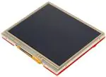
Figure 1. BOOSTXL-K350QVG-S1 BoosterPack
1
2
3
4
5
Contents
Getting Started ...............................................................................................................
1.1
Introduction ..........................................................................................................
1.2
Key Features ........................................................................................................
1.3
What's Included .....................................................................................................
1.4
Next Steps: Looking Into the Provided Code ...................................................................
Hardware......................................................................................................................
2.1
Hardware Features .................................................................................................
2.2
Design Files .........................................................................................................
2.3
Hardware Change log ..............................................................................................
Software Examples ..........................................................................................................
3.1
BOOSTXL-K350QVG-S1 + MSP-EXP432P401R Graphics Library Example ..............................
Additional Resources ........................................................................................................
4.1
TI LaunchPad Portal................................................................................................
4.2
Download CCS, IAR, Keil, or Energia ............................................................................
4.3
The Community .....................................................................................................
Schematics ...................................................................................................................
2
2
2
2
2
3
3
5
5
5
5
6
6
6
7
8
Trademarks
BoosterPack, LaunchPad, E2E, Code Composer Studio are trademarks of Texas Instruments.
All other trademarks are the property of their respective owners.
SLAU601B – March 2015 – Revised April 2020
Submit Documentation Feedback
BOOSTXL-K350QVG-S1 QVGA Display BoosterPack™ Plug-in Module
Copyright © 2015–2020, Texas Instruments Incorporated
1
�Getting Started
1
Getting Started
1.1
Introduction
www.ti.com
The BOOSTXL-K350QVG-S1 Kentec QVGA Display BoosterPack is an easy-to-use plug-in module for
adding a touch-screen color display to your LaunchPad kit design. MCU LaunchPad developers can use
this BoosterPack to start developing applications using the 320×240-pixel SPI-controlled TFT QVGA
display with resistive touch screen.
1.2
Key Features
•
•
•
Kentec TFT LCD (part number: K350QVG-V2-F)
– 3.5-inch QVGA (320×240 resolution)
– SPI communication
– 4-wire resistive touch screen
– White LED backlight
LED backlight driver circuit
Complies with the BoosterPack standard for use with 20- and 40-pin LaunchPads
1.3
What's Included
1.3.1
Kit Contents
• One BOOSTXL-K350QVG-S1 BoosterPack Plug-in module
1.3.2
Software Examples
• MSP-EXP432P401R LaunchPad + BOOSTXL-K350QVG-S1 demos (see Section 3)
– Graphics Library Example
1.4
Next Steps: Looking Into the Provided Code
After the EVM features have been explored, the fun can begin. It's time to open an integrated
development environment (IDE) and start looking at the code examples. Section 3 describes the example
projects available to make it easy to understand the provided software.
2
BOOSTXL-K350QVG-S1 QVGA Display BoosterPack™ Plug-in Module
Copyright © 2015–2020, Texas Instruments Incorporated
SLAU601B – March 2015 – Revised April 2020
Submit Documentation Feedback
�Hardware
www.ti.com
2
Hardware
Figure 2. BOOSTXL-K350QVG-S1 Overview
2.1
2.1.1
Hardware Features
BoosterPack Pinout
Figure 3. BoosterPack Pinout (View From Bottom of PCB)
SLAU601B – March 2015 – Revised April 2020
Submit Documentation Feedback
BOOSTXL-K350QVG-S1 QVGA Display BoosterPack™ Plug-in Module
Copyright © 2015–2020, Texas Instruments Incorporated
3
�Hardware
www.ti.com
The Kentec QVGA Display BoosterPack adheres to the 40-pin LaunchPad and BoosterPack pinout
standard. A standard was created to aid compatibility between LaunchPad and BoosterPack tools across
the TI ecosystem.
The 40-pin standard is compatible with the 20-pin standard that is used by other LaunchPad kits like the
MSP-EXP430FR4133. However, this BoosterPack is intended for use with 40-pin LaunchPad kits. If
compatibility is needed with a 20-pin LaunchPad, some modifications must be made for access to certain
pins and to provide 5 V for the LCD backlight circuitry.
More information about compatibility can also be found at http://www.ti.com/launchpad.
2.1.2
Kentec QVGA Display (K350QVG-V2-F)
The Kentec TFT display has the following features:
• 3.5-inch diagonal screen
• 320×240-pixel resolution
• Full color (262000 colors) RGB display
• 4-wire resistive touch screen
• Integrated SSD2119 LCD driver/controller
• SPI interface by default, but supports many interface types
Additional information about the K350QVG-V2-F display can be found on the Kentec website.
2.1.3
SSD2119 LCD Driver
The SSD2119 LCD driver is integrated into the display. In order to use the display effectively, a deep
understanding of this driver is required. The SSD2119 data sheet contains information about the
communication interface and the supported commands.
2.1.4
LCD Backlight Circuitry
Most of the circuitry seen on the BoosterPack is a boost converter to power the LCD backlight. The LCD
requires approximately 20 V to power the LCD backlight due to the serial voltage drops of the LEDs. This
power is derived from the 5-V (VUSB) power rail.
2.1.5
SPI Configuration
By default the BOOSTXL-K350QVG-S1 comes configured as a "4-wire" 8-bit SPI. This is the standard SPI
on most MCUs with a hardware SPI peripheral. The user can reconfigure R2/R3 and R8/R9 to instead use
"3-wire" 9-bit SPI. In this configuration, each SPI write is 9 bits instead of 8, allowing one fewer GPIO pin
to be used.
Table 1. SPI Resistor Configuration
LCD Interface
Resistor Configuration
R2
R8
R9
4-wire SPI, 8-bit (default)
DNP
0
DNP
0
3-wire SPI, 9-bit
0
DNP
0
DNP
Other (such as parallel)
4
R3
Pins PS0, PS1, PS2, PS3 as indicated in LCD data sheet.
This may require cutting and soldering these traces (not common)
BOOSTXL-K350QVG-S1 QVGA Display BoosterPack™ Plug-in Module
Copyright © 2015–2020, Texas Instruments Incorporated
SLAU601B – March 2015 – Revised April 2020
Submit Documentation Feedback
�Hardware
www.ti.com
Table 2 describes the SPI configuration pin functions.
Table 2. SPI Pin Definition
LCD Interface
Pin Name
LCD_SCS
2.2
2.2.1
LCD_SCL
LCD_SDI
LCD_SDC
4-wire SPI,
8-bit (default)
SPI Chip Select
SPI Clock
SPI Data In
(no support for data out)
GPIO to indicate data or command
Data = 1
Command = 0
3-wire SPI, 9-bit
SPI Chip Select
SPI Clock
SPI Data In
(no support for data out)
N/A – controlled by extra bit (first bit)
Design Files
Hardware
Schematics can be found in Section 5. All design files including schematics, layout, bill of materials
(BOM), Gerber files, and documentation are available in a zip folder (SLAR098). This hardware design
was done in Altium Designer, a free viewer is available from
http://techdocs.altium.com/display/ADOH/Altium+Designer+Viewer.
2.2.2
Software
All design files including TI-TXT object-code firmware images, software example projects, and
documentation are available in the LaunchPad specific software folders. To see which LaunchPad kits
feature BOOSTXL-K350QVG-S1 examples, refer to the "What's Included" section on the tool folder.
2.3
Hardware Change log
Table 3. Hardware Change Log
PCB Revision
Description
Rev 1.0
Initial Release
3
Software Examples
3.1
BOOSTXL-K350QVG-S1 + MSP-EXP432P401R Graphics Library Example
The demos are available in the MSP Graphics Library ("grlib") and show how to use the library in a project
with the Kentec display. This demo shows the user how to enable the touch screen, create buttons, and
use graphics primitives including colors and images.
While the code examples in the library are based on MSP430 and MSP432 devices, this BoosterPack
module can also be used with SimpleLink devices like the CC13xx and CC26xx. For more information,
post your question to the TI E2E™ community.
The program begins by calibrating the touch screen. There is a routine that detects the four corner
coordinates to determine if an eligible rectangle boundary is formed. If the calibration was incorrect, a
message displays on the screen indicating the calibration failed. When successful, the calibration provides
a reference for all button presses throughout the rest of the program.
The next step is to select the mode of the program: display primitives or images. Each mode simply cycles
through without user interaction to show features of the display. In the graphics primitives mode, the
following primitives are shown:
• Pixels
• Lines
• Circles
• Rectangles
SLAU601B – March 2015 – Revised April 2020
Submit Documentation Feedback
BOOSTXL-K350QVG-S1 QVGA Display BoosterPack™ Plug-in Module
Copyright © 2015–2020, Texas Instruments Incorporated
5
�Additional Resources
•
www.ti.com
Text
The application is heavily commented to ensure it is very clear how to use the grlib APIs. The above
primitives are shown as well as the underlying concepts of grlib including background and foreground
colors, context, fonts, opacity, and more.
The images mode shows the drawing of a few different images both compressed and uncompressed.
Image compression can have a big impact to drawing speeds for simple images. To draw images with the
MSP Graphics Library, they must first be converted into the right file format. These files can be generated
by the Image Reformer tool that comes packaged with grlib. Launch this tool (.exe) from the grlib folder or
directly from TI Resource Explorer.
File Path: \utils\image-reformer\imagereformer.exe
TI Resource Explorer > MSPWare > Libraries > Graphics Library > MSP430 Image Reformer
The Image Reformer tool allows you to import images and output into grlib specific files to add to your
grlib project. Image Reformer does not manipulate any images (including color modifications, rotation, and
cropping)—any image manipulation must be done before importing into the Image Reformer tool. More
information about MSP grlib and the Image Reformer tool can be found in the application report Design
Considerations When Using MSP430 Graphics Library (SLAA548).
Figure 4. MSP430 Image Reformer
4
Additional Resources
4.1
TI LaunchPad Portal
More information about LaunchPad kits, supported BoosterPack modules, and available resources can be
found at:
• TI's LaunchPad portal: information about all LaunchPad kits from TI for all MCUs
4.2
Download CCS, IAR, Keil, or Energia
Although the files can be viewed with any text editor, more can be done with the projects if they are
opened with a development environment like Code Composer Studio™ (CCS) IDE, IAR Embedded
Workbench, Keil, or Energia.
6
BOOSTXL-K350QVG-S1 QVGA Display BoosterPack™ Plug-in Module
Copyright © 2015–2020, Texas Instruments Incorporated
SLAU601B – March 2015 – Revised April 2020
Submit Documentation Feedback
�Additional Resources
www.ti.com
4.3
4.3.1
The Community
TI E2E™ Community
Search the forums at http://e2e.ti.com. If you cannot find your answer, post your question to the
community.
4.3.2
Community at Large
Many online communities focus on the LaunchPad and BoosterPack ecosystem – for example,
www.43oh.com. You can find additional tools, resources, and support from these communities.
SLAU601B – March 2015 – Revised April 2020
Submit Documentation Feedback
BOOSTXL-K350QVG-S1 QVGA Display BoosterPack™ Plug-in Module
Copyright © 2015–2020, Texas Instruments Incorporated
7
�TOUCH_XP
TOUCH_YN
TOUCH_XN
TOUCH_YP
3V3
LCD_SCL
LCD_SDC
1
CN1
LED-A
GND
C6
10nF
R16
R15
GND
5V0
GND
C5
10nF
GND
J3
C4
10nF
GND
J1
1
1
21
2
2
22
3
3
23
4
4
24
5
5
25
6
6
26
7
7
27
8
8
28
9
9
29
10 10
30
GND
K350QVG-V2-F
GND
2
GND
LED_PWM
J4
J2
20
40
1
1
19
39
2
2
18
38
3
3
17
37
4
4
16
36
5
5
15
35
6
6
14
34
7
7
13
33
8
8
12
32
9
9
11
31
10 10
3V3
C1
100pF
GND
GND
AGND
LCD_SDI
R18
LCD_SCS
0R
3V3
RST
CS
SCLK
SDA
0R
0R
0R
0R
R7
R6
R5
R4
TOUCH_YP
TOUCH_XP
C7
10nF
GND
0R
0R
LCD_RST
TOUCH_XN R17
0R
2
3V3
NC
0R
NC
R3
R2
GND
TOUCH_YN
LCD_SDC
A
B
C
D
1
3
PS3
PS2
GND
1
0
3V3
PS0
0R
PS1
NC
GND
Interface Mode
LX
1
2
3
D1
4
D2
68R
1K
ZMM24
R12
SW
R13
LED-K
2.2uF
LED-A
C2
Revision
03
LED-K
LED-A
4-wire, 8-bit SPI interface (SCS, SCL, SDI, SDC) Default
R9=>R8
R3=>R2
L1
10uH
IN
U1
GND
FB
SS
SHDN
AIC1896
MBR0520LT1G
3-wire, 9-bit SPI interface (SCS, SCL, SDI)
6
5
4
NC
R14
4
2014/12/12
Sheet of
D:\KentecDisplay\..\BOOSTXL-K350QVG-S1_03.SchDoc
Drawn By:
Number
BOOSTXL-K350QVG-S1 circuit diagram
C8
33nF
LED Backlight Driver Circuit
R10
NC
Date:
File:
A4
Size
Title
LED_PWM
R11
0R
C3
68uF
5V0
0R
R9
R1
PS0 R8
3
A
B
C
D
Copyright © 2015–2020, Texas Instruments Incorporated
LED_K
LED_K
LED_A
LED_A
GND
XR
YB
XL
YT
GND
NC
NC
NC
RESET
CS
SPCLK
SDA-SDI
NC
NC
B0(D0)
B1(D1)
B2(D2)
B3(D3)
B4(D4)
B5(D5)
NC
NC
G0(D6)
G1(D7)
G2(D8)
G3(D9)
G4(D10)
G5(D11)
NC
NC
R0(D12)
R1(D13)
R2(D14)
R3(D15)
R4(D16)
R5(D17)
HSYNC
VSYNC
DCLK
AVDD
AVDD
VDD
VDD
RS
RD
WR
PS0
PS1
PS2
PS3
WSYNC
NC
DE
GND
GND
LED-K
1
2
3
4
5
6
7
8
9
10
11
12
13
14
15
16
17
18
19
20
21
22
23
24
25
26
27
28
29
30
31
32
33
34
35
36
37
38
39
40
41
42
43
44
45
46
47
48
49
50
51
52
53
54
55
56
57
58
59
60
LCD_RST
LCD_SCS
LCD_SCL
LCD_SDI
SLAU601B – March 2015 – Revised April 2020
Submit Documentation Feedback
BOOSTXL-K350QVG-S1 QVGA Display BoosterPack™ Plug-in Module
8
Schematics
5
www.ti.com
Schematics
Hardware design files can be downloaded from www.ti.com/lit/zip/slar098.
Figure 5. Schematics
�Revision History
www.ti.com
Revision History
NOTE: Page numbers for previous revisions may differ from page numbers in the current version.
Changes from July 21, 2015 to April 1, 2020 ................................................................................................................... Page
•
•
•
Changed the location of the demo software to the MSP Graphics Library ........................................................ 5
Added the paragraph that begins "While the code examples in the library..." .................................................... 5
Deleted former section 4.3 MSPWare and TI Resource Explorer .................................................................. 6
SLAU601B – March 2015 – Revised April 2020
Submit Documentation Feedback
Revision History
Copyright © 2015–2020, Texas Instruments Incorporated
9
�IMPORTANT NOTICE AND DISCLAIMER
TI PROVIDES TECHNICAL AND RELIABILITY DATA (INCLUDING DATA SHEETS), DESIGN RESOURCES (INCLUDING REFERENCE
DESIGNS), APPLICATION OR OTHER DESIGN ADVICE, WEB TOOLS, SAFETY INFORMATION, AND OTHER RESOURCES “AS IS”
AND WITH ALL FAULTS, AND DISCLAIMS ALL WARRANTIES, EXPRESS AND IMPLIED, INCLUDING WITHOUT LIMITATION ANY
IMPLIED WARRANTIES OF MERCHANTABILITY, FITNESS FOR A PARTICULAR PURPOSE OR NON-INFRINGEMENT OF THIRD
PARTY INTELLECTUAL PROPERTY RIGHTS.
These resources are intended for skilled developers designing with TI products. You are solely responsible for (1) selecting the appropriate
TI products for your application, (2) designing, validating and testing your application, and (3) ensuring your application meets applicable
standards, and any other safety, security, regulatory or other requirements.
These resources are subject to change without notice. TI grants you permission to use these resources only for development of an
application that uses the TI products described in the resource. Other reproduction and display of these resources is prohibited. No license
is granted to any other TI intellectual property right or to any third party intellectual property right. TI disclaims responsibility for, and you
will fully indemnify TI and its representatives against, any claims, damages, costs, losses, and liabilities arising out of your use of these
resources.
TI’s products are provided subject to TI’s Terms of Sale or other applicable terms available either on ti.com or provided in conjunction with
such TI products. TI’s provision of these resources does not expand or otherwise alter TI’s applicable warranties or warranty disclaimers for
TI products.
TI objects to and rejects any additional or different terms you may have proposed. IMPORTANT NOTICE
Mailing Address: Texas Instruments, Post Office Box 655303, Dallas, Texas 75265
Copyright © 2022, Texas Instruments Incorporated
�