www.ti.com
Table of Contents
User’s Guide
BQ2022A Evaluation Software
ABSTRACT
The BQ2022A is a 1 K-bit serial EPROM containing a factory-programmed, unique 48-bit identification number,
8-bit CRC generation, and an 8-bit family code. A 64-bit status register controls write protection and page
redirection.
The purpose of the evaluation software is to demonstrate the functionality of the BQ2022A. The BQ2022A
evaluation board can be used for one or two ICs.
The BQ2022A is ideal for applications such as battery pack configuration parameters, record maintenance, asset
tracking, product revision status, and access-code security.
Table of Contents
1 Kit Contents.............................................................................................................................................................................2
2 BQ2022A-Based Circuit Module............................................................................................................................................2
2.1 Test Points..........................................................................................................................................................................2
3 BQ2022A Circuit Module Schematic.....................................................................................................................................3
4 Circuit Module Physical Layouts...........................................................................................................................................4
5 BQ2022A Circuit Module List of Materials............................................................................................................................8
6 BQ2022AEVM Circuit Module Performance Specification Summary................................................................................ 8
7 EVM Hardware and Software Setup...................................................................................................................................... 8
7.1 Drivers and Software Installation....................................................................................................................................... 8
7.2 Hardware Connection........................................................................................................................................................ 9
8 Software Operation...............................................................................................................................................................10
8.1 Evaluation Software Pages.............................................................................................................................................. 10
8.2 ROM CMD........................................................................................................................................................................10
8.3 DATA.................................................................................................................................................................................11
9 Revision History................................................................................................................................................................... 12
List of Figures
Figure 3-1. EVM Schematic.........................................................................................................................................................3
Figure 4-1. Silk Screen................................................................................................................................................................ 4
Figure 4-2. EVM Top Assembly................................................................................................................................................... 5
Figure 4-3. EVM Layer One.........................................................................................................................................................6
Figure 4-4. EVM Layer Two......................................................................................................................................................... 7
Figure 8-1. ROM CMD Page......................................................................................................................................................11
Figure 8-2. DATA Page.............................................................................................................................................................. 12
List of Tables
Table 2-1. Test Points.................................................................................................................................................................. 2
Table 5-1. List of Materials...........................................................................................................................................................8
Table 6-1. Performance Specification Summary..........................................................................................................................8
Table 7-1. Wire Connection......................................................................................................................................................... 9
Trademarks
Microsoft® and Windows® are registered trademarks of Microsoft Corporation.
All trademarks are the property of their respective owners.
SLUU258C – NOVEMBER 2007 – REVISED FEBRUARY 2021
Submit Document Feedback
Copyright © 2022 Texas Instruments Incorporated
BQ2022A Evaluation Software
1
�Kit Contents
www.ti.com
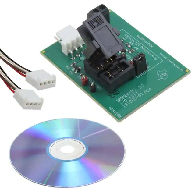
1 Kit Contents
1. BQ2022A, HPA125 revision-B board
2. CD-ROM including Microsoft® Windows® based PC software and support documentation
Note
An EV2400 board is required to interface this EVM with the PC and can be purchased separately.
The EV2400 up through at least version 0.18 does not support this EVM.
2 BQ2022A-Based Circuit Module
The BQ2022A-based circuit module is ideal for programming the 1 K-bit EPROM and the STATUS bytes of the
BQ2022A IC. The circuit module includes a 3-pin SOT23 dual socket, a BQ2022A IC, a Zener diode for host
protection during EPROM programming, and a programming circuit that generates a 12-V pulse when used
with a power supply and a control signal. In a typical application, only the BQ2022A IC and a pullup resistor is
required.
2.1 Test Points
Table 2-1 lists the EVM test points.
Table 2-1. Test Points
Test Point
DESCRIPTION
J1-1
VSS
Device ground
J1-2
PROG
Input for timing of EPROM programming pulse
J1-3
SDQ
SDQ single-wire communication bus
J2-1
12V
High voltage for EPROM programming
J2-2
VSS
J3
2
SIGNAL NAME
BQ2022A Evaluation Software
Programming ground
Connect for EPROM programming
SLUU258C – NOVEMBER 2007 – REVISED FEBRUARY 2021
Submit Document Feedback
Copyright © 2022 Texas Instruments Incorporated
�www.ti.com
BQ2022A Circuit Module Schematic
3 BQ2022A Circuit Module Schematic
The schematic shows the circuit for the BQ2022AEVM implementation.
Figure 3-1. EVM Schematic
SLUU258C – NOVEMBER 2007 – REVISED FEBRUARY 2021
Submit Document Feedback
Copyright © 2022 Texas Instruments Incorporated
BQ2022A Evaluation Software
3
�Circuit Module Physical Layouts
www.ti.com
4 Circuit Module Physical Layouts
This section contains the board layout and assembly drawings for the BQ2022AEVM circuit module.
Figure 4-1. Silk Screen
4
BQ2022A Evaluation Software
SLUU258C – NOVEMBER 2007 – REVISED FEBRUARY 2021
Submit Document Feedback
Copyright © 2022 Texas Instruments Incorporated
�www.ti.com
Circuit Module Physical Layouts
Figure 4-2. EVM Top Assembly
SLUU258C – NOVEMBER 2007 – REVISED FEBRUARY 2021
Submit Document Feedback
Copyright © 2022 Texas Instruments Incorporated
BQ2022A Evaluation Software
5
�Circuit Module Physical Layouts
www.ti.com
Figure 4-3. EVM Layer One
6
BQ2022A Evaluation Software
SLUU258C – NOVEMBER 2007 – REVISED FEBRUARY 2021
Submit Document Feedback
Copyright © 2022 Texas Instruments Incorporated
�www.ti.com
Circuit Module Physical Layouts
Figure 4-4. EVM Layer Two
SLUU258C – NOVEMBER 2007 – REVISED FEBRUARY 2021
Submit Document Feedback
Copyright © 2022 Texas Instruments Incorporated
BQ2022A Evaluation Software
7
�BQ2022A Circuit Module List of Materials
www.ti.com
5 BQ2022A Circuit Module List of Materials
Table 5-1 presents the list of materials required for the BQ2022AEVM circuit module.
Table 5-1. List of Materials
REF DES
QTY
DESCRIPTION
D1, D2
1
Diode, Zener, 5.6-V, 350-mW
MFR
Diodes, Inc.
PART NUMBER
BZX84C5V6
J3
1
Header, 2-pin, 100-mil spacing, (36-pin strip)
Sullins
PTC36SAAN
R1, R2, R6
3
Resistor, Chip, 100-Ω, 1/16-W
Std
Std
R3
1
Resistor, Chip, 100-kΩ, 1/16-W
Std
Std
R4
1
Resistor, Chip, 10-kΩ, 1/16-W
Std
Std
XU1
1
Socket, Double 3P SOT-23
Loranger
13293 121 X218A
J1
1
Header, Friction Lock Ass'y, 4-pin Right Angle
Molex
22-05-3041
J2
1
Terminal Block, 2-pin, 6-A, 3.5-mm
OST
ED1514
VSS1, VSS2
2
Test Point, Black, 1-mm
Keystone
5001
SDQ1, SDQ2
2
Test Point, Red, 1-mm
Keystone
5000
Q1
1
MOSFET, N-ch, 60-V, 115-mA, 1.2-Ω
Vishay-Liteon
2N7002DICT
Q2
1
MOSFET, Pch, -20V, 3.7A, 65 mΩ
IR
IRLML6402
U1
1
IC, 1 K Serial EPROM With SDQ Interface
TI
BQ2022ADBZR
–
1
PCB, 2 In x 1.25 In x .125 In
Any
HPA125 Rev. B Board
N/A
1
Shunt, 100-mil, Black
3M
929950-00
6 BQ2022AEVM Circuit Module Performance Specification Summary
Table 6-1 provides the performance specification summary.
Table 6-1. Performance Specification Summary
SPECIFICATION
MIN
TYP
MAX
UNITS
Voltage Pullup (VUP)
2.65
5.5
V
Programming Voltage(VPP)
11.5
12
V
7 EVM Hardware and Software Setup
7.1 Drivers and Software Installation
This section describes how to install the BQ2022AEVM PC software, and how to connect the different
components of the EVM.
Use the following steps to install the BQ2022A evaluation software:
1.
2.
3.
4.
5.
6.
7.
8.
9.
10.
11.
12.
13.
8
Insert the CD ROM into a CD ROM drive.
Select the CD ROM drive using My Computer or File Manager.
Select the ReadMeFirst.txt file.
Select the Software/EV2400 Drivers directory of CD and run SETUP.EXE.
Plug the EV2400 into a USB port.
Wait until system prompt new hardware found appears. Choose select location manually, and use the
browse button to point to subdirectory TIUSBWin2K-XP-1.
Answer continue to the warning that drivers are not certified with Microsoft.
After installation finishes, another system prompt new hardware found appears. Repeat procedure above,
but point to subdirectory TIUSBWin2K-XP-2.
Answer continue to the warning that drivers are not certified with Microsoft. Installation of drivers is now
finished.
For Microsoft® Windows® 98, point to directory TIUSBWin98.
After installing the USB drivers for EV2400, double-click on the Setup.exe icon that is under the Software/
bq2022A Evaluation Software folder.
Follow the instructions on screen during the installation of evaluation software.
The setup program installs a Windows application group.
BQ2022A Evaluation Software
SLUU258C – NOVEMBER 2007 – REVISED FEBRUARY 2021
Submit Document Feedback
Copyright © 2022 Texas Instruments Incorporated
�www.ti.com
EVM Hardware and Software Setup
7.2 Hardware Connection
The BQ2022AEVM has three hardware components. :
1. The BQ2022AEVM circuit module
2. The PC interface board, (EV2400 – purchased separately)
3. The PC
Use the following steps to configure the hardware for interface to the PC:
1. Connect the HPA125 board with the EV2400 PC interface board using Table 7-1 as a pin connection guide.
2. Connect the USB cable to the EV2400 and the PC USB port.
The BQ2022AEVM is now set up for normal operation.
Table 7-1. Wire Connection
BQ2022AEVM (HPA125 Rev. B)
EV2400
SDQ
HDQ
VSS
GND
PROG
VOUT
To program the EPROM of BQ2022AEVM, a 12-V pulse must be generated on the SDQ line. The HPA125 board
has an additional circuit included that permits generating this pulse when using a power supply set to 12 V and
the VOUT output of the EV2400. The evaluation software controls this pulse for EPROM programming.
When programming the EPROM, it is expected that a 12-V supply must be connected to the HPA125 board at
the 12-V input terminal of the HPA125 board. Ensure that the ground of the power supply is connected to VSS of
the board.
A jumper (J3) must be connected when using the EPROM programming circuit.
7.2.1 Normal Operation
Normal operation includes performing any of the ROM commands, reading the 1 K-bit EPROM and reading the
EPROM Status Memory.
7.2.2 EPROM Programming
To program EPROM registers, a 12-V pulse must be sent across the SDQ line after sending the code 0x5A
during a write command. See the BQ2022A data sheet (SLUS724) for a specific description of EPROM
programming requirements. When programming EPROM registers, the following must be ensured:
•
•
•
J3 jumper is connected.
VOUT output of EV2400 is connected to PROG input of HPA125 board.
Power supply set to 12 V is connected across the 12 V and VSS inputs of HPA125 board.
SLUU258C – NOVEMBER 2007 – REVISED FEBRUARY 2021
Submit Document Feedback
Copyright © 2022 Texas Instruments Incorporated
BQ2022A Evaluation Software
9
�Software Operation
www.ti.com
8 Software Operation
Run the program from the Start|Programs|Texas Instruments|bq2022A Evaluation Software menu sequence.
8.1 Evaluation Software Pages
This section describes the function of each page of the EVSW.
8.2 ROM CMD
This page provides all the ROM commands for BQ2022A (see Figure 8-1).
8.2.1 Sections Within the ROM CMD Page
Application This section determines the number of BQ2022A devices that are on the SDQ bus. If only one
device is used, then select Single Device. This option sends the SKIP ROM command before
any communication attempt is made with the device. If more than one device is used, then
select Multiple Devices. This option sends the MATCH ROM command before any communication
attempt is made with the desired device
Search ROM This section demonstrates the SEARCH ROM command. When multiple devices are on the SDQ
bus, the ROM ID of the devices that share the bus is listed.
Match
ROM
This section is only available when the Multiple Devices option is selected in the Application section.
To use the MATCH ROM, enter the ROM ID of the device of interest in the text box, and then click
on the Select Device button. This causes the MATCH ROM commands with the desired ROM ID to
be sent whenever communication is attempted with the desired device. If SEARCH ROM is used, the
desired ID can be copied from the SEARCH ROM list, and then pasted into the MATCH ROM text box.
Ensure that only the ID numbers are pasted into the text box and not the whole line referring to the
device.
Read ROM This section is only available when the Single Device option is selected in the Application section.
The ID ROM of the device on the SDQ communication line is displayed.
10
BQ2022A Evaluation Software
SLUU258C – NOVEMBER 2007 – REVISED FEBRUARY 2021
Submit Document Feedback
Copyright © 2022 Texas Instruments Incorporated
�www.ti.com
Software Operation
Figure 8-1. ROM CMD Page
8.3 DATA
This page (see Figure 8-2) allows the user to program the 1 K-bit EPROM with desired values and to program
the STATUS bytes. It requires that the hardware is set up as described in the EPROM programming of this
user’s guide.
8.3.1 1 K-Bit EPROM
The EPROM memory map is organized in four pages of 32 bytes each. All registers can be read by clicking on
the Read Memory button. As the registers of a specific page are being read, the page number is highlighted in
red.
The two methods of programming the EPROM using the EVSW follow.
1. Click on a specific grid that corresponds to the register that needs to be written. Write the hexadecimal value
of the data that needs to be written, and then press ENTER.
2. The other method of programming the EPROM is by importing a data file that contains all the values to be
programmed. The data file has the file extension .epr. An example of a data file is included with the EVSW.
To create additional data files, modify the example file so that the values on the right side of the file represent
the desired values. Save the file with a different name ensuring that the extension .epr is used. To import a
file into the grid, go to File|Open Data File, and select the appropriate file. Once the file is opened, the grid
is filled in with the values contained in the data file. Click on the Write Memory button so that the values are
programmed into the EPROM.
A data file can also be saved by going to File|Save Data File. The data that is saved in the file is the data
displayed on the grids representing the EPROM memory map.
SLUU258C – NOVEMBER 2007 – REVISED FEBRUARY 2021
Submit Document Feedback
Copyright © 2022 Texas Instruments Incorporated
BQ2022A Evaluation Software
11
�Software Operation
www.ti.com
8.3.2 Status Bytes
This section allows the user to read or write the EPROM Status bytes of the BQ2022A. The registers are
programmed by clicking on the appropriate grid, entering the desired value, and pressing ENTER.
Buttons are provided for the user to select specific pages for write protection. By selecting any of the Write
Protection Bits button, register 0x00 of status registers is written automatically so that the corresponding bit is
cleared.
Note that the status registers are EPROM. Once a bit has been cleared, it cannot be set.
Figure 8-2. DATA Page
9 Revision History
NOTE: Page numbers for previous revisions may differ from page numbers in the current version.
Changes from Revision B (July 2017) to Revision C (February 2021)
Page
• Updated the numbering format for tables, figures, and cross-references throughout the document..................2
• Updated user guide to use EV2400 instead of EV2300 (NRND)........................................................................2
Changes from Revision A (October 2013) to Revision B (July 2017)
Page
• Added note regarding EV2400 board versions...................................................................................................2
12
BQ2022A Evaluation Software
SLUU258C – NOVEMBER 2007 – REVISED FEBRUARY 2021
Submit Document Feedback
Copyright © 2022 Texas Instruments Incorporated
�IMPORTANT NOTICE AND DISCLAIMER
TI PROVIDES TECHNICAL AND RELIABILITY DATA (INCLUDING DATA SHEETS), DESIGN RESOURCES (INCLUDING REFERENCE
DESIGNS), APPLICATION OR OTHER DESIGN ADVICE, WEB TOOLS, SAFETY INFORMATION, AND OTHER RESOURCES “AS IS”
AND WITH ALL FAULTS, AND DISCLAIMS ALL WARRANTIES, EXPRESS AND IMPLIED, INCLUDING WITHOUT LIMITATION ANY
IMPLIED WARRANTIES OF MERCHANTABILITY, FITNESS FOR A PARTICULAR PURPOSE OR NON-INFRINGEMENT OF THIRD
PARTY INTELLECTUAL PROPERTY RIGHTS.
These resources are intended for skilled developers designing with TI products. You are solely responsible for (1) selecting the appropriate
TI products for your application, (2) designing, validating and testing your application, and (3) ensuring your application meets applicable
standards, and any other safety, security, regulatory or other requirements.
These resources are subject to change without notice. TI grants you permission to use these resources only for development of an
application that uses the TI products described in the resource. Other reproduction and display of these resources is prohibited. No license
is granted to any other TI intellectual property right or to any third party intellectual property right. TI disclaims responsibility for, and you
will fully indemnify TI and its representatives against, any claims, damages, costs, losses, and liabilities arising out of your use of these
resources.
TI’s products are provided subject to TI’s Terms of Sale or other applicable terms available either on ti.com or provided in conjunction with
such TI products. TI’s provision of these resources does not expand or otherwise alter TI’s applicable warranties or warranty disclaimers for
TI products.
TI objects to and rejects any additional or different terms you may have proposed. IMPORTANT NOTICE
Mailing Address: Texas Instruments, Post Office Box 655303, Dallas, Texas 75265
Copyright © 2022, Texas Instruments Incorporated
�