bq2040
Gas Gauge IC With SMBus Interface
Features
General Description
➤ Provides accurate measurement
of available charge in NiCd,
NiMH, and Li-Ion batteries
The bq2040 Gas Gauge IC With
SMBus Interface is intended for
battery-pack or in-system installation to maintain an accurate record
of available battery charge. The
bq2040 directly supports capacity
monitoring for NiCd, NiMH, and LiIon battery chemistries.
➤ Supports SBS v1.0 data set and
two-wire interface
➤ Monitors charge FET in Li-Ion
pack protection circuit
➤ Designed for battery pack integration
-
Low operating current
Complete circuit can fit on less
than ¾ square inch of PCB
space
➤ Supports SBS charge control
commands for NiCd, NiMH, and
Li-Ion
➤ Drives a four-segment LED display for remaining capacity
indication
The bq2040 uses the System Management Bus v1.0 (SMBus) protocol
and supports the Smart Battery
Data (SBData) commands. The
bq2040 also supports the SBData
charge control functions. Battery
state-of-charge, remaining capacity,
remaining time, and chemistry are
av ai l a b l e o v e r th e s e ri a l l i n k.
Battery-charge state can be directly
indicated using a four-segment LED
display to graphically depict battery
full-to-empty in 25% increments.
The bq2040 estimates battery selfdischarge based on an internal
timer and temperature sensor and
user-programmable rate information stored in external EEPROM.
The bq2040 also automatically recalibrates or “learns” battery capacity in the full course of a discharge
cycle from full to empty.
The bq2040 may operate directly
from three nickel chemistry cells.
With the REF output and an external transistor, a simple, inexpensive
regulator can be built to provide
VCC for other battery cell configurations.
An external EEPROM is used to
program initial values into the
bq2040 and is necessary for proper
operation.
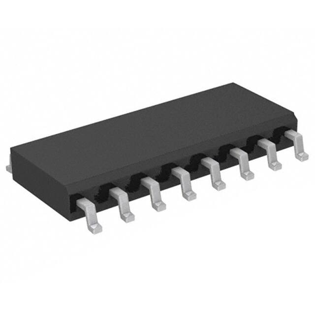
➤ 16-pin narrow SOIC
Pin Connections
Pin Names
VCC
3.0–6.5V
SB
Battery sense input
VCC
1
16
VOUT
ESCL
EEPROM clock
PSTAT Protector status input
ESCL
2
15
REF
ESDA
EEPROM data
SMBD
SMBus data input/output
ESDA
3
14
SMBC
LED1-4
LED segment 1-4
SMBC
SMBus clock
LED1
4
13
SMBD
VSS
System ground
REF
Voltage reference output
LED2
5
12
PSTAT
SR
Sense resistor input
VOUT
EEPROM supply output
LED3
6
11
SB
DISP
Display control input
LED4
7
10
DISP
VSS
8
9
SR
16-Pin Narrow SOIC
PN204001.eps
SLUS005–JUNE 1999 E
1
�bq2040
DISP
Pin Descriptions
VCC
Supply voltage input
ESCL
Serial memory clock
DISP high disables the LED display. DISP
floating allows the LED display to be active
during charge if the rate is greater than
100mA. DISP low activates the display for
4 seconds.
Output used to clock the data transfer between the bq2040 and the external nonvolatile configuration memory.
ESDA
SB
LED display segment outputs
PSTAT
Each output may drive an external LED.
VSS
Ground
SR
Sense resistor input
Secondary battery input
Monitors the pack voltage through a highimpedance resistor divider network. The
pack voltage is reported in the SBD register
function Voltage (0x09) and is monitored for
end-of-discharge voltage and charging voltage parameters.
Serial memory data and address
Bidirectional pin used to transfer address
and data to and from the bq2040 and the external nonvolitile configuration memory.
LED1–
LED4
Display control input
Protector status input
Provides overvoltage status from the Li-Ion
protector circuit and can initiate a charge suspend request.
SMBD
The voltage drop (VSR) across pins SR and
VSS is monitored and integrated over time
to interpret charge and discharge activity.
The SR input is connected to the sense resistor and the negative terminal of the
battery. VSR < VSS indicates discharge, and
VSR > VSS indicates charge. The effective
voltage drop, VSRO, as seen by the bq2040
is VSR + VOS. (See Table 3.)
SMBus data
Open-drain bidirectional pin used to transfer
address and data to and from the bq2040.
SMBC
SMBus clock
Open-drain bidirectional pin used to clock
the data transfer to and from the bq2040.
REF
Reference output for regulator
REF provides a reference output for an optional FET-based micro-regulator.
VOUT
Supply output
Supplies power to the external EEPROM configuration memory.
2
�bq2040
Figure 1 shows a typical battery pack application of the
bq2040 using the LED capacity display, the serial port,
and an external EEPROM for battery pack programming information. The bq2040 must be configured and
calibrated for the battery-specific information to ensure
proper operation. Table 1 outlines the configuration information that must be programmed in the EEPROM.
Functional Description
General Operation
The bq2040 determines battery capacity by monitoring
the amount of charge put into or removed from a rechargeable battery. The bq2040 measures discharge
and charge currents, estimates self-discharge, and
monitors the battery for low-battery voltage thresholds.
The charge is measured by monitoring the voltage
across a small-value series sense resistor between the
battery's negative terminal and ground. The available
battery charge is determined by monitoring this voltage
over time and correcting the measurement for the environmental and operating conditions.
An internal temperature sensor eliminates the need
for an external thermistor—reducing cost and components. An internal, temperature-compensated timebase eliminates the need for an external resonator,
further reducing cost and components. The entire circuit in Figure 1 can occupy less than 3 4 square inch of
board space.
(Optional)
VCC
VOUT
ESCL
ESDA
LED1
LED2
LED3
LED4
VSS
REF
SMBC
SMBD
PSTAT
SB
DISP
SR
bq2040
Chart 1
For bq2040 With No D8
NiMH
Li-Ion
No. of Cells
R5
R11
R4
Q1
2
301K
604K
100K
BSS138
3
4
499K
806K
100K
BSS138
698K
604K
100K
2N7002
6
499K
499K
100K
BSS138
8
698K
806K
100K
BSS138
9
806K
499K
100K
2N7002
10
909K
604K
100K
2N7002
12
909K
909K
86.5K
2N7002
(Optional)
2040LED.eps
Figure 1. Battery Pack Application Diagram—LED Display
3
�bq2040
Table 1. Configuration Memory Map
Parameter Name
Address
Description
EEPROM length
0x00
Number of EEPROM data locations
must = 0x64
EEPROM check1
0x01
EEPROM data integrity check byte, must = 0x5b
Length
Units
8 bits
NA
8 bits
NA
Remaining time alarm
0x02/0x03 Sets RemainingTimeAlarm (0x02)
16 bits
minutes
Remaining capacity alarm
0x04/0x05 Sets RemainingCapacityAlarm (0x01)
16 bits
mAh
Reserved
0x06/0x07 Reserved for future use
16 bits
NA
Initial charging current
0x08/0x09 Sets the initial charging current
16 bits
mA
Charging voltage
0x0a/0x0b Sets ChargingVoltage (0x15)
16 bits
mV
Battery status
0x0c/0x0d Initializes BatteryStatus (0x16)
16 bits
NA
Cycle count
0x0e/0x0f Initializes and stores CycleCount (0x17)
16 bits
cycles
Design capacity
0x10/0x11 Sets DesignCapacity (0x18)
16 bits
mAh
Design voltage
0x12/0x13 Sets DesignVoltage (0x19)
16 bits
mV
Specification information
0x14/0x15 Programs SpecificationInfo (0x1a)
16 bits
NA
Manufacture date
0x16/0x17 Programs ManufactureDate (0x1b)
16 bits
NA
Serial number
0x18/0x19 Programs SerialNumber (0x1c)
16 bits
NA
Fast-charging current
0x1a/0x1b Sets ChargingCurrent (0x14)
16 bits
mA
Maintenance-charge current
0x1c/0x1d Sets the trickle current request
16 bits
mA
Reserved
0x1e/0x1f Reserved must = 0x0000
16 bits
mAh
Manufacturer name
0x20-0x2b Programs ManufacturerName (0x20)
96 bits
NA
Current overload
0x2c/0x2d Sets the overload current threshold
16 bits
mA
Battery low %
0x2e
Sets the battery low amount
8 bits
%
Reserved
0x2f
Reserved for future use
8 bits
NA
Device name
0x30-0x37 Programs DeviceName (0x21)
64 bits
NA
Li-Ion taper current
Sets the upper limit of the taper current for charge
0x38/0x39
termination
16 bits
mA
Maximum overcharge limit
0x3a/0x3b Sets the maximum amount of overcharge
16 bits
NA
Reserved must = 0x00
8 bits
NA
0x3d
Locks commands outside of the SBS data set
8 bits
NA
0x3e
Initializes FLAGS1
8 bits
NA
0x3f
Initializes FLAGS2
8 bits
NA
Reserved
0x3c
Access protect
FLAGS1
FLAGS2
Device chemistry
0x40-0x45 Programs DeviceChemistry (0x22)
48 bits
NA
Current measurement gain
0x46/0x47 Sense resistor calibration value
16 bits
NA
Battery voltage offset
0x48
Voltage calibration value
8 bits
NA
Temperature offset
0x49
Temperature calibration value
8 bits
NA
Maximum temperature and
∆T step
0x4a
Sets the maximum charge temperature and the ∆T
step for ∆T/∆t termination
8 bits
NA
4
�bq2040
Table 1. Configuration Memory Map (Continued)
Length
Units
Charge efficiency
Parameter Name
Address
0x4b
Sets the high/low charge rate efficiencies
Description
8 bits
NA
Full charge percentage
0x4c
Sets the percent at which the battery is considered fully charged
8 bits
NA
Digitial filter
0x4d
Sets the minimum charge/discharge threshold
8 bits
NA
Current integration gain
0x4e
Programs the current integration gain to the
sense resistor value
8 bits
NA
Self-discharge rate
0x4f
Sets the battery’s self-discharge rate
8 bits
NA
Manufacturer data
0x50-0x55 Programs ManufacturerData (0x23)
48 bits
NA
Voltage gain1
0x56/0x57 Battery divider calibration value
16 bits
NA
Reserved
0x58-0x59 Reserved
16 bits
NA
EDVF charging current
Sets the charge current request when the battery
0x5a/0x5b
voltage is less than EDVF
16 bits
NA
End of discharge voltage1
0x5c/0x5d Sets EDV1
16 bits
NA
End of discharge voltage final
0x5e/0x5f Sets EDVF
16 bits
NA
Full-charge capacity
0x60/0x61 Initializes and stores FullChargeCapacity (0x10)
16 bits
mAh
Sets the ∆t step for ∆T/∆t termination
8 bits
NA
∆t step
0x62
Hold-off time
0x63
Sets ∆T/∆t hold-off timer
8 bits
NA
0x64
EEPROM data integrity check byte
must = 0xb5
8 bits
NA
EEPROM check 2
Reserved
0x65-0x7f Reserved for future use
5
NA
�bq2040
Voltage Thresholds
Layout Considerations
In conjunction with monitoring VSR for charge/discharge
currents, the bq2040 monitors the battery potential
through the SB pin. The voltage potential is determined through a resistor-divider network per the following equation:
The bq2040 measures the voltage differential between
the SR and VSS pins. VOS (the offset voltage at the SR
pin) is greatly affected by PC board layout. For optimal
results, the PC board layout should follow the strict rule
of a single-point ground return. Sharing high-current
ground with small signal ground causes undesirable
noise on the small signal nodes. Additionally, in reference to Figure 1:
R5
MBV
=
− 1
R4
2.25
where MBV is the maximum battery voltage, R5 is connected to the positive battery terminal, and R4 is connected to the negative battery terminal. R5/R4 should be
rounded to the next higher integer. The voltage at the
SB pin (VSB) should never exceed 2.4V.
n
n
The battery voltage is monitored for the end-ofdischarge voltages (EDV1 and EDVF) and for alarm
warning conditions. EDV threshold levels are used to determine when the battery has reached a programmable
“empty” state. The bq2040 generates an alarm warning
when the battery voltage exceeds the maximum charging voltage by 5% or if the voltage is below EDVF. The
battery voltage gain, the two EDV thresholds, and the
charging voltage are programmable in the EEPROM.
n
The capacitors (C1 and C2) should be placed as close as
possible to the SB and VCC pins, and their paths to VSS
should be as short as possible. A high-quality ceramic
capacitor of 0.1µf is recommended for VCC.
The sense resistor capacitor (C3) should be placed as
close as possible to the SR pin.
The bq2040 should be in thermal contact with the
cells for optimum temperature measurement.
Gas Gauge Operation
The operational overview diagram in Figure 2 illustrates the operation of the bq2040. The bq2040 accumulates a measure of charge and discharge currents, as
well as an estimation of self-discharge. Charge currents
are compensated for temperature and state-of-charge of
the battery. Self-discharge is temperature-compensated.
If VSB is below either of the two EDV thresholds, the associated flag is latched and remains latched, independent of
VSB, until the next valid charge.
EDV monitoring may be disabled under certain conditions. If the discharge current is greater than the value
stored in location 0x2c and 0x2d in the EEPROM (EE
0x2c/0x2d), EDV monitoring is disabled and resumes after the current falls below the programmed value.
The main counter, RemainingCapacity (RM), represents
the available battery capacity at any given time. Battery
charging increments the RM register, whereas battery discharging and self-discharge decrement the RM register
and increment the internal Discharge Count Register
(DCR).
Reset
The bq2040 is reset when first connected to the battery
pack. On power-up, the bq2040 initializes and reads the
EEPROM configuration memory. The bq2040 can also
be reset with a command over the SMBus. The software
reset sequence is the following: (1) write MaxError
(0x0c) to 0x0000; (2) write the reset register (0x64) to
0x8009. A software reset can only be performed if the
bq2040 is in an unlocked state as defined by the value in
location 0x3d of the EEPROM (EE 0x3d) on power-up.
The Discharge Count Register is used to update the
FullChargeCapacity (FCC) register only if a complete
battery discharge from full to empty occurs without any
partial battery charges. Therefore, the bq2040 adapts
its capacity determination based on the actual conditions of discharge.
The battery's initial full capacity is set to the value stored
in EE 0x60-0x61. Until FCC is updated, RM counts up to,
but not beyond, this threshold during subsequent charges.
Temperature
The battery’s empty state is also programmed in the
EEPROM. The battery low percentage (EE 0x2e) stores
the percentage of FCC that will be written to RM when
the battery voltage drops below the EDV1 threshold.
The bq2040 monitors temperature sensing using an internal sensor. The temperature is used to adapt charge
and self-discharge compensations as well as to monitor
for maximum temperature and ∆T/∆t during a bq2040
controlled charge. Temperature may also be accessed
over the SMBus with command 0x08.
1.
FullChargeCapacity or learned-battery
capacity:
FCC is the last measured discharge capacity of the
battery. On initialization (application of VCC or reset),
FCC is set to the value stored in the EEPROM. Dur-
6
�bq2040
Inputs
Charge
Current
Discharge
Current
Self-Discharge
Timer
State-of-charge
and
Temperature
Compensation
Temperature
Compensation
Main Counters
and Capacity
Reference (FCC)
+
-
+ Remaining
Capacity
(RM)
<
Full
Charge
Capacity
(FCC)
+
Discharge
Count
Qualified Register
Transfer (DCR)
Temperature, Other Data
Outputs
Chip-Controlled
Two-Wire
Available Charge Serial Interface
LED Display
FG294501.eps
Figure 2. Operational Overview
ing subsequent discharges, FCC is updated with the
latest measured capacity in the Discharge Count Register plus the battery low amount, representing a discharge from full to below EDV1. A qualified discharge is necessary for a capacity transfer from the
DCR to the FCC register. Once updated, the bq2040
writes the new FCC to the EEPROM. The FCC also
serves as the 100% reference threshold used by the
relative state-of-charge calculation and display.
2.
3.
4.
Discharge Count Register (DCR):
The DCR counts up during discharge independent
of RM and can continue increasing after RM has
decremented to 0. Prior to RM = 0, both discharge
and self-discharge increment the DCR. After RM
= 0, only discharge increments the DCR. The DCR
resets to 0 when RM = FCC and stops counting at
EDV1 on discharge. The DCR does not roll over but
stops counting when it reaches FFFFh.
DesignCapacity (DC):
The DC is the user-specified battery capacity and is
programmed from external EEPROM. The DC also
provides the 100% reference for the absolute display mode.
FCC is updated on the first charge after a qualified
discharge to EDV1. The updated FCC equals the
battery low percentage times the current FCC plus
the DCR value. A qualified discharge to EDV1 occurs if all of the following conditions exist:
RemainingCapacity (RM):
n
RM counts up during charge to a maximum value of
FCC and down during discharge and self-discharge to
0. RM is set to the battery low amount after the
EDV1 threshold has been reached. If RM is already
equal to or less than the battery low amount, RM is
not modified. If RM reaches the battery low amount
before the battery voltage falls below EDV1 on discharge, RM stops counting down until the EDV1
threshold is reached. RM is set to 0 when the battery
voltage reaches EDVF. To prevent overstatement of
charge during periods of overcharge, RM stops incrementing when RM = FCC. RM may optionally
be written to a user-defined value when fully
charged if the battery pack is under bq2040 charge
control. On initialization, RM is set to 0.
n
n
n
No valid charge initiations (charges greater than
10mAh, where VSRO > +VSRD occurred during
the period between RM = FCC and EDV1 detected.
The self-discharge count is not more than
256mAh.
The low temperature fault bit in FLAGS2 is not
set when the EDV1 level is reached during discharge.
Battery voltage is not more than 256mV below
the EDV1 threshold when EDV1 is set.
The valid discharge flag (VDQ) in FLAGS1 indicates whether the present discharge is valid for an
FCC update. FCC cannot be reduced by more than
256mAh during any single cycle.
7
�bq2040
Charge Counting
Current Taper
Charge activity is detected based on a positive voltage
on the SR input. If charge activity is detected, the
bq2040 increments RM at a rate proportional to VSRO
and, if enabled, activates an LED display. Charge actions increment the RM after compensation for charge
state and temperature.
For Li-Ion charge control, the ChargingVoltage must be
set to the desired pack voltage during the constant voltage charge phase. The bq2040 detects a current taper
termination when it measures the pack voltage to be
within 128mV of the requested charging voltage and
when the AverageCurrent is less than the programmed
threshold in EE 0x38—0x39 and non-zero for at least
100s.
The bq2040 determines charge activity sustained at a
continuous rate equivalent to VSRO > +VSRD. A valid
charge equates to sustained charge activity
greater than 10 mAh. Once a valid charge is detected,
charge threshold counting continues until VSRO falls below VSRD. VSRD is a programmable threshold as described in the Digital Magnitude Filter section.
∆T/∆t
The ∆T/∆t used by the bq2040 is programmable in both
the temperature step (1.6°C–4.6°C) and time step (20
seconds–320seconds). Typical settings for 1°C/min include 2°C over 120 seconds and 3°C over 180 seconds.
Longer times are required for increased slope resolution.
Discharge Counting
∆T
∆T
is set by the formula:
=
∆t
∆t
All discharge counts where VSRO < -VSRD cause the RM
register to decrement and the DCR to increment. VSRD
is a programmable threshold as described in the Digital
Magnitude Filter section.
[(lower nibble of EE 0x4a)∗ 2 + 16 ] / 10
[320 − (EE 0x62) ∗ 20)]
Self-Discharge Estimation
oC
s
In addition to the ∆T/∆t timer, there is a hold-off timer,
which starts when the battery is being charged at more
than 255mA and the temperature is above 25°C. Until
this timer expires, ∆T/∆t is suspended. If the temperature falls below 25°C, or if charging current falls below
255mA, the timer is reset and restarts only if these conditions are once again within range. The hold-off time is
programmed in EE 0x63.
The bq2040 continuously decrements RM and increments DCR for self-discharge based on time and temperature provided that the discharge flag in BatteryStatus
is set (charge not detected). The bq2040 self-discharge
estimation rate is programmed in EE 0x4f and can be
set from 0 to 25% per day for 20–30°C. This rate approximately doubles for every 10°C increase until the temperature is ≥ 70°C or halves every 10°C decrease until
the temperature is < 10°C.
Charge Termination
Charge Control
Once the bq2040 detects a valid charge termination, the
Fully_Charged, Terminate_Charge_Alarm, and the
Over_Charged_Alarm bits are set in BatteryStatus, and
the requested charge current is set to zero. Once the
te rmi n a ti n g co n d i ti o n s ce a s e, th e Te rm inate_Charge_Alarm and the Over_Charged_Alarm are
cleared, and the requested charging current is set to the
maintenance rate. The bq2040 requests the maintenance rate until RM falls below the amount determined
by the programmable full- charge percentage. Once this
occurs, the Fully_Charged bit is cleared, and the requested charge current and voltage are set to the
fast-charge rate.
The bq2040 supports SBS charge control by broadcasting the ChargingCurrent and the ChargingVoltage to
the Smart Charger address. The bq2040 broadcasts
charging commands every 10 seconds; the broadcasts
can be disabled by writing bit 14 of BatteryMode to 1.
On reset, the initial charging current broadcast to the
charger is set to the value programmed in EE 0x080x09. The bq2040 updates the value used in the charging current broadcasts based on the battery’s state of
charge, voltage, and temperature.
The bq2040 internal charge control is compatible with
nickel-based and Li-Ion chemistries. The bq2040 uses
current taper detection for Li-Ion primary charge termination and ∆T/∆t for nickel based primary charge termination. The bq2040 also provides a number of safety
terminations based on battery capacity, voltage, and
temperature.
Bit 4 (CC) in FLAGS2 determines whether RM is modified after a ∆T/∆t or current taper termination occurs. If
CC = 1, RM may be set from 0 to 100% of the FullChargeCapacity as defined in EE 0x4c. If RM is below the
full-charge percentage, RM is set to the full-charge percentage of FCC. If RM is above the full-charge percentage, RM is not modified.
8
�bq2040
Charge Suspension
Count Compensations
The bq2040 may temporarily suspend charge if it detects
a charging fault. The charging faults include the following conditions:
Charge activity is compensated for temperature and
state-of-charge before updating the RM and/or DCR.
Self-discharge estimation is compensated for temperature before updating RM or DCR.
n Maximum Overcharge: If charging continues for
more than the programmed maximum overcharge
limit as defined in EE 0x3a—0x3b beyond RM=FCC,
the Fully_Charged bit is set, and the requested
charging current is set to the maintenance rate.
Charge Compensation
Charge efficiency is compensated for state-of-charge,
temperature, and battery chemistry. The charge efficiency is adjusted using the following equations:
n Overvoltage: An over-voltage fault exists when the
bq2040 measures a voltage more than 5% above the
ChargingVoltage.
When the bq2040 detects an
overvoltage condition, the requested charge current is
set to 0 and the Terminate_Charge_Alarm bit is set
in BatteryStatus. The alarm bit is cleared when the
current drops below 256mA and the voltage is less
than 105% of ChargingVoltage.
1.) RM = RM * (Q EFC − Q ET )
where RelativeStateOfCharge < FullChargePercentage,
and Q EFC is the programmed fast-charge efficiency varying from 0.75 to 1.0.
2.) RM = RM * (Q ETC − Q ET )
where RelativeStateOfCharge ≥ FullChargePercentage
and Q ETC is the programmed maintenance (trickle)
charge efficiency varying from 0.75 to 1.0.
n Overcurrent: An overcurrent fault exists when the
bq2040 measures a charge current more than 25%
above the ChargingCurrent. If the ChargingCurrent
is less than 1024mA, an overcurrent fault exists if the
charge current is more than 1mA above the lowest
multiple of 256mA that exceeds the ChargingCurrent.
When the bq2040 detects an overcurrent condition, the
requested charge current is set to 0 and the
Terminate_Charge_Alarm bit is set in Battery Status.
The alarm bit is cleared when the current drops below
256mA.
Q ET is used to adjust the charge efficiency as the battery
temperature increases according to the following:
Q ET = 0 if T < 30°C
Q ET = 0.02 if 30 ° C ≤ T < 40 ° C
Q ET = 0.05 if T ≥ 40 ° C
QET is 0 over the entire temperature range for Li-Ion.
n Maximum Temperature: When the battery
temperature equals the programmed maximum
temperature, the requested charge current is set to
zero
and
the
Over_Temp_Alarm
and
the
Terminate_Charge_Alarm bits are set in Battery
Status. The Over_Temp_Alarm bit is cleared when
the temperature drops to 43°C below the maximum
temperature threshold minus 5°C.
Digital Magnitude Filter
The bq2040 has a programmable digital filter to eliminate charge and discharge counting below a set
threshold, VSRD. Table 2 shows typical digital filter
settings. The proper digital filter setting can be calculated using the following equation.
n PSTAT: When the PSTAT input is ≥1.5V, the
requested charge current is set to 0 and the
Terminate_Charge_Alarm bit is set in BatteryStatus
if the Discharging flag is not set. The alarm bit is
cleared when the PSTAT input is 15°C
1
Temperature < 12°C
Where IMIN is:
Bit 0, the Overcurrent flag (OC), is set when Current is
25% greater than the programmed charging current. If
the charging current is programmed less than 1024mA,
overcurrent is set if Current is 256mA greater than the
programmed charging current. This flag is cleared when
Current falls below 256mA.
0
A valid current taper termination condition
is not present.
1
Valid current taper termination condition
detected.
The Valid Charge flag (VQ), bit 5, is set when VSRO ≥
|VSRD| and 10mAh of charge has accumulated. This bit
is cleared during a discharge and when VSRO ≤ |VSRD|.
The OC value is:
7
-
6
-
FLAGS2 Bits
4
3
2
-
5
-
1
-
7
-
0
OC
1
Current is less than 1.25 ∗ ChargingCurrent or less than 256mA if charging current
is programmed less than 1024mA
Current exceeds 1.25 ∗ ChargingCurrent or
256mA if the charging current is programmed less than 1024mA. This bit is
cleared if Current < 256mA.
1
-
0
-
FLAGS1 Bits
5
4
3
-
2
-
1
-
0
V SRO ≤ |V SRD |
1
V SRO ≥ |V SRD | and 10mAh of charge has
accumulated
The Valid Discharge flag (VDQ), bit 3, is set when a
valid discharge is occurring (discharge cycle valid for
learning new full charge capacity) and cleared if a partial charge is detected, EDV1 is asserted when T < 0°C,
or self-discharge accounts for more than 256mAh of the
discharge.
The ∆T/∆t value is:
∆T/∆t
2
-
Bit 4 is reserved.
Bits 7 indicates that a ∆T/∆t termination condition
exists.
6
-
FLAGS1 Bits
4
3
-
Where VQ is:
FLAGS1
7
5
VQ
The VQ value is:
Where OC is:
0
6
-
7
-
0
-
6
-
5
-
FLAGS1 Bits
4
3
VDQ
2
-
1
-
0
-
The VDQ value is:
Where ∆T/∆t is:
Where VDQ is:
0
The ∆T/∆t rate drops below the programmed rate.
1
The ∆T/∆t rate exceeds the programmed
rate.
6
IMIN
5
-
FLAGS1 Bits
4
3
-
2
-
1
-
Self-discharge is greater than 256mAh,
EDV1 = 1 when T < 0°C or VQ = 1
1
On first discharge after RM=FCC
The Overload flag (OVLD), bit 2, is set when the discharge current is greater than the programmed rate and
cleared when the discharge current falls below the programmed rate.
Bit 6 indicates that a current taper termination condition exists.
7
-
0
0
-
7
-
19
6
-
5
-
FLAGS1 Bits
4
3
2
OVLD
1
-
0
-
�bq2040
The OVLD value is:
SBD Seal
Where OVLD is:
0
Current < programmed rate
1
Current > programmed rate
The bq2040 address space can be “locked” to enforce the
SBS specified access to each command code. To lock the
address space, the bq2040 must be initialized with EE
0x3d set to b0h. Once this is done, only commands
0x00-0x04 may be written. Attempting to write to any
other address will cause a “no acknowledge” of the data.
Reading will only be permitted from the command codes
listed in the SBD specification plus the five locations
designated as optional manufacturing functions 1–5
(0x2f, 0x3c–0x3f).
The First End-of-Discharge Voltage flag (EDV1), bit 1, is
set when Voltage < EDV1 and OVLD = 0 and cleared
when VQ = 1 and Voltage > EDV1.
7
-
6
-
5
-
FLAGS1 Bits
4
3
2
-
1
EDV1
0
-
Programming the bq2040
The EDV1 value is:
The bq2040 requires the proper programming of an external EEPROM for proper device operation. Each module can be calibrated for the greatest accuracy, or general “default” values can be used. An EV2200-40 programming kit (interface board, software, and cable) for
an IBM-compatible PC is available from Benchmarq.
Where EDV1 is:
0
VQ = 1 and Voltage > EDV1
1
Voltage < EDV1 and OVLD = 0
The Final End-of-Discharge Voltage flag (EDVF), bit 0, is
set when Voltage < EDVF and OVLD = 0 and cleared
when VQ = 1 and Voltage > EDVF.
7
-
6
-
5
-
FLAGS1 Bits
4
3
2
-
1
-
The bq2040 uses a 24LC01 or equivalent serial EEPROM (capable of read operation to 2.0V) for storing the
various initial values, calibration data, and string information. Table 1 outlines the parameters and addresses
for this information. Tables 10 and 11 detail the various
register contents and show an example program value
for an 2400mAh 4-series Li-Ion battery pack, using a
50mΩ sense resistor.
0
EDVF
The EDVF value is:
Where EDVF is:
0
VQ = 1 and Voltage > EDVF
1
Voltage < EDVF and OVLD = 0
Error Codes and Status Bits
Error codes and status bits are listed in Table 8 and Table 9, respectively.
20
�bq2040
Table 8. Error Codes (BatteryStatus() (0x16))
Error
Code
Access
Description
OK
0x0000
read/write bq2040 processed the function code without detecting any errors.
Busy
0x0001
read/write bq2040 is unable to process the function code at this time.
ReservedCommand
0x0002
read/write
UnsupportedCommand
0x0003
read/write bq2040 does not support the requested function code.
AccessDenied
0x0004
Overflow/Underflow
0x0005
BadSize
0x0006
UnknownError
0x0007
Note:
write
bq2040 cannot read or write the data at this time—try again
later.
bq2040 detected an attempt to write to a read-only function
code.
read/write bq2040 detected a data overflow or underflow.
write
bq2040 detected an attempt to write to a function code with an
incorrect size data block.
read/write bq2040 detected an unidentifiable error.
Reading the bq2040 after an error clears the error code.
21
�bq2040
Table 9. BatteryStatus Bits
Alarm Bits
Bit Name
Set When:
Reset When:
OVER_CHARGED_ALARM
The bq2040 detects a ∆T/∆t or current taper termination. (Note:
∆T/∆t and current taper are valid
charge terminations.)
A discharge occurs or when the
∆T/∆t or current taper termination
condition ceases during charge.
TERMINATE_CHARGE_ALARM
The bq2040 detects an over-current,
over-voltage, over-temperature,
∆T/∆t, or current taper condition
during charge.
A discharge occurs or when all conditions causing the event cease.
OVER_TEMP_ALARM
The bq2040 detects that its internal
temperature is greater than the programmed value.
Internal temperature falls to 43°C or
the maximum temperature threshold
minus 5°C.
TERMINATE_DISCHARGE_ALARM
The bq2040 determines that it has
supplied all the charge that it can
without being damaged (Voltage <
EDVF).
Voltage > EDVF signifies that the
battery has reached a state of charge
sufficient for it to once again safely
supply power.
REMAINING_CAPACITY_ALARM
Either the value set by the RemainThe bq2040 detects that the RemainingCapacityAlarm function is lower
ingCapacity is less than that set by
than the Remaining Capacity or the
the RemainingCapacityAlarm funcRemainingCapacity is increased by
tion.
charging.
REMAINING_TIME_ALARM
The bq2040 detects that the estimated remaining time at the present
discharge rate is less than that set
by the RemainingTimeAlarm function.
Either the value set by the RemainingTimeAlarm function is lower than
the AverageTimeToEmpty or a valid
charge is detected.
Status Bits
Bit Name
Set When:
Reset When:
INITIALIZED
The bq2040 loads from the EEPROM
A bad EEPROM load is detected.
(bit 7 set in EE0x0c).
DISCHARGING
The bq2040 determines that it is not Battery detects that it is being
being charged.
charged.
FULLY_CHARGED
The bq2040 determines a valid
charge termination or a maximum
overcharge state.
RM discharges below the full charge
percentage.
FULLY_DISCHARGED
bq2040 determines that it has
supplied all the charge that it can
without being damaged.
RelativeStateOfCharge is greater
than or equal to 20%
22
�bq2040
Table 10. Example Register Contents
EEPROM
Address
Description
Low
Byte
High
Byte
EEPROM
Hex Contents
Low
Byte
High
Byte
Example
Values
Notes
EEPROM
length
0x00
64
100
Must be equal to 0x64.
EEPROM check 1
0x01
5b
91
Must be equal to 0x5b.
Remaining time
alarm
0x02
0x03
0a
00
Remaining
capacity alarm
0x04
0x05
f0
00
240mAh
Sets the low capacity alarm level.
Reserved
0x06
0x07
00
00
0
Not currently used by the bq2040.
Initial charging
current
0x08
0x09
60
09
2400mA
Sets the initial charge request.
Charging voltage
0x0a
0x0b
d8
40
16600mV
Used to set the fast-charge voltage for the Smart
Charger.
Battery status
0x0c
0x0d
80
00
128
Cycle count
0x0e
0x0f
00
00
0
10 minutes Sets the low time alarm level.
Initializes BatteryStatus.
Contains the charge cycle count and can be set to zero
for a new battery.
Design capacity
0x10
0x11
60
09
2400mAh
Normal battery pack capacity.
Design voltage
0x12
0x13
40
38
14400mV
Nominal battery pack voltage.
Specification
information
0x14
0x15
10
00
1.0
Manufacture
date
0x16
0x17
a1
20
Serial number
0x18
0x19
12
27
Default value for this register in a 1.0 part.
May 1, 1996
Packed per the ManufactureDate description.
= 8353
10002
Fast-charging
current
0x1a
0x1b
60
09
2400mA
Maintenance
charge current
0x1c
0x1d
00
00
0mA
Reserved
0x1e
0x1f
00
00
0
Current
overload
0x2c
Battery low %
0x2e
0x2d
70
08
17
Contains the optional pack serial number.
Used to set the fast-charge current for the Smart
Charger.
Contains the desired maintenance current after fastcharge termination by the bq2040.
Must be programmed to 0x00.
6000mA
Sets the discharge current at which EDV threshold
monitoring is disabled.
Sets the battery capacity that RemainingCapacity is
reduced to at EDV1. The value equals 2.56 ∗ (%RM at
EDV1)
3%
23
�bq2040
Table 10. Example Register Contents (Continued)
EEPROM
Address
Description
Low
Byte
High
Byte
EEPROM
Hex
Contents
Low High
Byte Byte
00
Example
Values
Reserved
0x2f
Li-Ion taper
current
0x38
0x39
10
ff
240mA
Sets the upper taper limit for Li-Ion charge termination. Stored in 2’s complement.
Maxi m um
overcha r g e
lim it
0x3a
0x3b
9c
ff
100mAh
Sets the maximum amount of overcharge before a
maximum overcharge charge suspend occurs.
Stored in 2’s complement.
Reserved
0x3c
00
Access protect
0x3d
b0
FLAGS1
0x3e
00
FLAGS2
0x3f
Current
measurement
gain1
0x46
Battery voltage
0x48
offset1
0
Notes
0
00
fe
Must be programmed to 0.
If the bq2040 is reset and bit 3 of this location is 0, the
bq2040 locks access to any command outside of the SBS
SBD access only
data set. Program to 0xb8 for full R/W access, 0xb0 for
SBD access only.
0
Initializes FLAGS1
Relative display
Li-Ion chemistry
Initializes FLAGS2.
bq2040 charge
control
b0
0x47
Not currently used by the bq2040.
0f
3840
The current gain measurement and current integration gain are related and defined for the bq2040 current measurement. This word equals 192/sense resistor value in ohms.
-2mV
Used to adjust the battery voltage offset according to
the following:
Voltage = (VSB(mV) + VOFF) ∗ Voltage gain
13.8°C
The default value (zero adjustment) for the offset is
12.8°C or 0x80.
TOFFNEW = TOFFCURRENT +
(TEMPACTUAL - TEMPREPORTED)∗ 10
Temperature
offset1
0x49
8a
Maximum
temperature
and ∆T step
0x4a
5f
Maximum
Maximum charge temperature is 69- (mt ∗ 1.6)°C (mt
temperature =
= upper nibble). The ∆T step is (dT ∗ 2 + 16)/10°C
61.0°C
(dT = lower nibble).
∆T step = 4.6°C
ff
Maintenance
compensation =
100%
Fast compensation = 100%
Charge
efficiency
0x4b
Full-charge
percentage
Note:
0x4c
9c
Sets the fast-charge (high) and maintenance charge
(low) efficiencies. The upper nibbles sets the low efficiency and the lower nibble adjusts the high efficiency according to the equation:
Nibble = (efficiency% ∗ 256 - 196)/4
This packed field is the two’s complement of the desired value in RM when the bq2040 determines a
full-charge termination. If RM is below this value,
RM is set to this value. If RM is above this value,
then RM is not adjusted.
100%
1. Can be adjusted to calibrate the battery pack.
24
�bq2040
Table 10. Example Register Contents (Continued)
EEPROM
Address
Description
Digital filter
EEPROM
Hex
Contents
Low High Low High
Byte Byte Byte Byte
0x4d
96
Example
Values
Notes
0.30mV
Used to set the digital magnitude filter as described in
Table 2.
3.2/0.05
Represents the following: 3.2/sense resistor in ohms.
It is used by the bq2040 to scale the measured voltage
values on the SR pin in mA and mAh. This register
also compensates for variations in the reported sense
resistor value.
0.25%
This packed field is the two’s complement of (52.73/x)
where x is the desired self-discharge rate per day (%)
at room temperature.
Voltage gain is packed as two units. For example, (R4
+ R5)/R4 = 7.09 would be stored as: whole number
stored in 0x57 as 7 and the decimal component stored
in 0x56 as 256 x 0.09 = 23(= 17h).
Current integration gain1
0x4e
40
Self-discharge rate
0x4f
2d
Voltage gain1
0x56 0x57
17
07
7.09
Reserved
0x58 0x59
00
00
0
EDVF charging
current
0x5a 0x5b
64
00
100mA
End of discharge
voltage 1
0x5c 0x5d
20
d1
12000mV
The value programmed is the two’s complement of the
threshold voltage in mV.
End-of-discharge
voltage final
0x5e
0x5f
40
d4
11200mV
The value programmed is the two’s complement of the
threshold voltage in mV.
Full charge
capacity
0x60 0x61
d0
07
2000mA
This value sets the initial estimated pack capacity.
∆t step
0x62
0f
Hold-off time
0x63
00
EEPROM check 2 0x64
b5
Reserved
Note:
0x65
0x7f
0
Should be programmed to 0.
Contains the desired charge current below EDVF.
The ∆t step for ∆T/∆t termination equals
320 - (byte value ∗ 20).
20s
320s hold-off The hold-off time is 320 - (byte value ∗ 20).
181
Must be equal to 0xb5.
NA
Not currently used by the bq2040.
1. Can be adjusted to calibrate the battery pack.
25
�bq2040
Table 11. Example Register Contents (String Data)
String Description
Address
0x
X0
0x
X1
0x
X2
0x
X3
0x
X4
0x
X5
0x
X6
0x
X7
0x
X8
0x
X9
0x
Xa
0x
Xb
52
R
51
Q
-
-
Manufacturer name
0x200x2b
09
42
B
45
E
4e
N
43
C
48
H
4d
M
41
A
Device name
0x300x37
06
42
B
51
Q
32
2
30
0
34
4
30
0
-
Device chemistry
0x400x45
04
6c
L
69
I
4f
O
4e
N
-
Manufacturer data
0x500x55
05
42
B
51
Q
32
2
30
0
32
2
26
�bq2040
Absolute Maximum Ratings
Minimum
Maximum
Unit
VCC
Symbol
Relative to VSS
-0.3
+7.0
V
All other pins
Relative to VSS
-0.3
+7.0
V
REF
Relative to VSS
-0.3
+8.5
V
Current limited by R11 (see Figure 1)
VSR
Relative to VSS
-0.3
+7.0
V
Minimum 100Ω series resistor should
be used to protect SR in case of a
shorted battery.
TOPR
Operating temperature
0
+70
°C
Commercial
Note:
Parameter
Notes
Permanent device damage may occur if Absolute Maximum Ratings are exceeded. Functional operation should be limited to the Recommended DC Operating Conditions detailed in this data sheet. Exposure to conditions beyond the operational limits for extended periods of time may affect device reliability.
DC Voltage Thresholds (TA = TOPR; V = 3.0 to 5.5V)
Symbol
Parameter
Minimum
Typical
Maximum
Unit
-50mV
-
50mV
V
Notes
EVSB
Battery voltage error relative to SB
Note:
The accuracy of the voltage measurement may be improved by adjusting the battery voltage offset and
gain, stored in external EEPROM. For best operation, VCC should be 1.5V greater than VSB.
27
See note
�bq2040
Recommended DC Operating Conditions (TA = TOPR)
Symbol
VCC
VREF
RREF
ICC
Parameter
Minimum
Typical
Maximum
Unit
Notes
Supply voltage
3.0
4.25
6.5
V
VCC excursion from < 2.0V to ≥
3.0V initializes the unit.
Reference at 25°C
5.7
6.0
6.3
V
IREF = 5µA
Reference at -40°C to +85°C
4.5
-
7.5
V
IREF = 5µA
Reference input impedance
2.0
5.0
-
MΩ
VREF = 3V
-
90
135
µA
VCC = 3.0V
-
120
180
µA
VCC = 4.25V
-
170
250
µA
VCC = 5.5V
Normal operation
VSB
Battery input
0
-
VCC
V
RSBmax
SB input impedance
10
-
-
MΩ
IDISP
DISP input leakage
-
-
5
µA
VDISP = VSS
ILVOUT
VOUT output leakage
-0.2
-
0.2
µA
EEPROM off
VSR
Sense resistor input
-0.3
-
2.0
V
VSR < VSS = discharge;
VSR > VSS = charge
RSR
SR input impedance
10
-
-
MΩ
-200mV < VSR < VCC
VIH
0.5 ∗ VCC
-
VCC
V
ESCL, ESDA
Logic input high
1.4
-
5.5
V
SMBC, SMBD
0
-
0.3 ∗ VCC
V
ESCL, ESDA
0.6
V
SMBC, SMBD
IOL=350µA, SMBC, SMBD
VIL
Logic input low
-0.5
VOL
Data, clock output low
IOL
Sink current
VOLSL
0 < VSB < VCC
-
-
0.4
V
100
-
350
µA
VOL≤0.4V, SMBC, SMBD
LEDX output low, low VCC
-
0.1
-
V
VCC = 3V, IOLS ≤ 1.75mA
LED1–LED4
VOLSH
LEDX output low, high VCC
-
0.4
-
V
VCC = 6.5V, IOLS ≤ 11.0mA
LED1–LED4
VOHVL
VOUT output, low VCC
VCC - 0.3
-
-
V
VCC = 3V, IVOUT = -5.25mA
VOHVH
VOUT output, high VCC
VCC - 0.6
-
-
V
IVOUT
VOUT source current
-33
-
-
mA
At VOHVH = VCC - 0.6V
IOLS
LEDX sink current
11.0
-
mA
At VOLSH = 0.4V
Note:
All voltages relative to VSS.
28
VCC = 6.5V, IVOUT = -33.0mA
�bq2040
AC Specifications
Min
Max
Units
FSMB
Symbol
SMBus operating frequency
Parameter
10
100
KHz
TBUF
Bus free time between stop and
start condition
4.7
µs
THD:STA
Hold time after (repeated) start
condition
4.0
µs
TSU:STA
Repeated start condition setup time
4.7
µs
TSU:STO
Stop condition setup time
4.0
µs
THD:DAT
Data hold time
300
ns
TSU:DAT
Data setup time
250
ns
TLOW
Clock low period
4.7
µs
THIGH
Clock high period
4.0
µs
TF
Clock/data fall time
300
ns
TR
Clock/data rise time
1000
ns
TLOW:SEXT
Cumulative clock low extend time
(slave)
25
ms
35
ms
25
TTIMEOUT
Notes
Bus Timing Data
tR
SMBC
tHIGH
tSU:STA
tHD:STA
tLOW
tHD:DAT
tSU:DAT
tSU:STO
SMBD
tF
tBUF
TD294501.eps
29
�bq2040
16-Pin SOIC Narrow (SN)
16-Pin SN (SOIC Narrow)
D
e
Dimension
Minimum
A
0.060
A1
0.004
B
0.013
C
0.007
D
0.385
E
0.150
e
0.045
H
0.225
L
0.015
All dimensions are in inches.
B
E
H
A
C
A1
.004
L
30
Maximum
0.070
0.010
0.020
0.010
0.400
0.160
0.055
0.245
0.035
�bq2040
Data Sheet Revision History
ChangeNo.
Page No.
3
3
Updated recommended application schematic.
3
9
Changed overcurrent fault conditon for ChargingCurrent < 1024mA.
3
10
4Hz operation of LED clarification.
3
11
Added descriptions for bits 7 and 13 of BatteryMode.
3
14
AtRateTimeToEmpty and AtRateTimeToFull invalid data indication correction.
3
15, 16
RunTimeToEmpty, AverageTimeToEmpty and AverageTimeToFull invalid data
indication corrections.
3
23
Notes:
Description of Change
Changed typical Battery low % value for Li-Ion with EDV1 = 3.0V/cell.
3
24
Li-Ion taper current is stored in 2’s complement.
3
24
Changed typical ∆T step and Full-charge percentage for Li-Ion.
3
25
Voltage gain is (R4 + R5)/R4.
3
25
Changed typical EDV1 and EDVF values for Li-Ion.
4
6
Added VSB should not exceed 2.4V
4
8
The self discharge rate approx imately doubles or halves
4
11
Changed cycle count increase from 30 to 32 for condition request.
4
14
Changed AtRateOK() indication from EDV1 to EDVF
4
25
Changed self-discharge programming from 52.75/x to 52.73/x.
4
25
Changed recommended EDVF charging current from 0mA to 100mA
Changes 1 and 2 refer to the 1998 Data Book
Change 3 = June1998 D changes from Jan. 1998 C.
Change 4 = June 1999 E changes from June 1998 D.
Ordering Information
bq2040
Temperature Range:
blank = Commercial (0 to 70°C)
Package Option:
SN = 16-pin narrow SOIC
Device:
bq2040 Gas Gauge IC With SMBus Interface
31
�PACKAGE OPTION ADDENDUM
www.ti.com
10-Dec-2020
PACKAGING INFORMATION
Orderable Device
Status
(1)
Package Type Package Pins Package
Drawing
Qty
Eco Plan
(2)
Lead finish/
Ball material
MSL Peak Temp
Op Temp (°C)
Device Marking
(3)
(4/5)
(6)
BQ2040SN-C408
ACTIVE
SOIC
D
16
40
RoHS & Green
NIPDAU
Level-2-260C-1 YEAR
0 to 70
2040
C408
BQ2040SN-D111
ACTIVE
SOIC
D
16
40
RoHS & Green
NIPDAU
Level-2-260C-1 YEAR
0 to 70
2040
D111
BQ2040SN-D111TR
ACTIVE
SOIC
D
16
2500
RoHS & Green
NIPDAU
Level-2-260C-1 YEAR
0 to 70
2040
D111
BQ2040SN-D111TRG4
ACTIVE
SOIC
D
16
2500
RoHS & Green
NIPDAU
Level-2-260C-1 YEAR
0 to 70
2040
D111
(1)
The marketing status values are defined as follows:
ACTIVE: Product device recommended for new designs.
LIFEBUY: TI has announced that the device will be discontinued, and a lifetime-buy period is in effect.
NRND: Not recommended for new designs. Device is in production to support existing customers, but TI does not recommend using this part in a new design.
PREVIEW: Device has been announced but is not in production. Samples may or may not be available.
OBSOLETE: TI has discontinued the production of the device.
(2)
RoHS: TI defines "RoHS" to mean semiconductor products that are compliant with the current EU RoHS requirements for all 10 RoHS substances, including the requirement that RoHS substance
do not exceed 0.1% by weight in homogeneous materials. Where designed to be soldered at high temperatures, "RoHS" products are suitable for use in specified lead-free processes. TI may
reference these types of products as "Pb-Free".
RoHS Exempt: TI defines "RoHS Exempt" to mean products that contain lead but are compliant with EU RoHS pursuant to a specific EU RoHS exemption.
Green: TI defines "Green" to mean the content of Chlorine (Cl) and Bromine (Br) based flame retardants meet JS709B low halogen requirements of