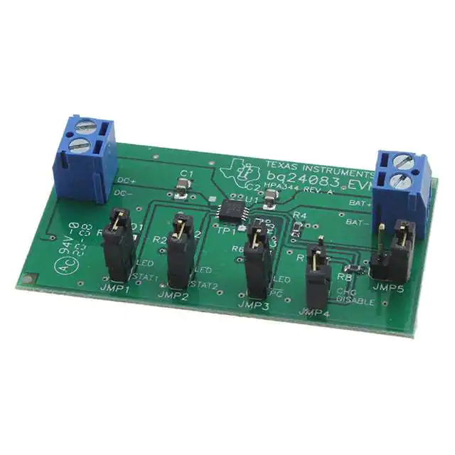
User's Guide
SLUU315 – June 2008
bq24083 1-A, Single-Cell Li-Ion and Li-Polymer Charge
Management IC EVM
1
Introduction
This user's guide describes the bq24083 evaluation module (EVM). The EVM provides a convenient
method for evaluating the performance of a charge management solution for portable applications. A
complete designed and tested charger is presented. The charger is designed to deliver up to 1 A of
continuous charge current for single-cell Li-ion or Li-polymer applications using a dc power supply. The
charger is programmed from the factory to deliver 0.7 A of charging current.
1.1
Background
The bq24083 is a highly integrated and flexible Li-ion linear charge and system power management
device targeted at space-limited charger applications. The bq24083 integrated circuit (IC) offers an
integrated power FET and current sensor, high-accuracy current and voltage regulation, charge status,
and charge termination in a single monolithic device. An external resistor sets the magnitude of the charge
current. The bq24083 charges the battery in three phases: conditioning, constant current, and constant
voltage. The constant voltage can be programmed to 4.2 V without pullup on VBSEL and 4.1 V with a
pullup (JMP5). Charge is terminated based on minimum current. An internal charge timer provides a
backup safety for charge termination. The bq24083 automatically restarts the charge if the battery voltage
falls below an internal threshold. The bq24083 automatically enters sleep mode when the input is
removed.
1.2
Performance Specification Summary
Table 1. Performance Specification Summary
SPECIFICATION
Input dc voltage, VI(DC)
Battery charge current, IO(CHG)
Power dissipation
2
TEST CONDITIONS
MIN
V(REG) + 0.5
TYP
MAX
UNIT
5
6.5
0.7
1
A
1.5
W
V
Test Summary
This section shows the test setups used and the tests performed in evaluating the EVM. See the bq24083
data sheet (SLUS848) for complete details regarding the operation and specifications.
2.1
Test Setup
The bq24083EVM board requires a regulated 5-Vdc, 1-A power source to provide input power and a
single-cell Li-ion or Li-polymer battery pack.
The test setup connections and jumper setting selections are configured for a stand-alone evaluation but
can be changed to interface with external hardware such as a microcontroller.
SLUU315 – June 2008
Submit Documentation Feedback
bq24083 1-A, Single-Cell Li-Ion and Li-Polymer Charge Management IC EVM
1
�Test Summary
www.ti.com
Table 2. I/O and Jumper Connections
JACK
2.2
CONNECTION
J1-DC+
Power supply positive connection, preset to 5 Vdc, 1-A current limit.
J1-DC-
Power supply return connection, ground
J2-BAT+
Positive battery pack terminal
J2-BAT–
Negative battery pack terminal, BAT- is common with DC-
JMP1-STAT1
JMP1-2 STAT1 signal. Place shunt on JMP1 for LED, indication.
JMP2-STAT2
JMP2-2 STAT2 signal. Place shunt on JMP2 for LED indication.
JMP3-PG
JMP3-2 PG signal. Place shunt on JMP3 for LED indiction.
JMP4-CE
Charge Enable-active low. Place shunt on JMP4 to pull CE Hi. Remove shunt for CE = Low
JMP5-VBSEL
JMP5-2 VBSEL signal. Place shunt on JMP5 to change output regulation from 4.2 V to 4.1 V.
Test Procedures
Set up the evaluation board as previously described by making the necessary I/O connections and jumper
selections. Prior to test and evaluation, it is important to verify that the maximum power dissipation on the
device is not exceeded: PMAX = 1.5 W.
(
)
PMAX = V(DC+) - V(BAT+)
x I(CHG)
(1)
1. Turn on the power supply, which is preset to 5 Vdc, and 1 A for the current limit setting.
2. The bq24083 enters preconditioning mode if the battery is below the V(LOWV) threshold. In this mode,
the bq24083 precharges the battery with a low current, typically
IO(CHG)
10
3.
4.
5.
6.
7.
2.3
=
0.7 A
10
= 70 mA
(2)
until the battery voltage reaches the V(LOWV) threshold or until the precharge timer expires. If the
timer expires, then the charge current is terminated and the bq24083 enters fault mode. Both LEDs
turn off when in fault mode. Toggling input power or battery replacement resets fault mode. Note that
the several fault conditions that can occur are described in the data sheet (SLUS848).
Once the battery voltage is above the V(LOWV) threshold, the battery enters fast-charge mode. This
EVM is programmed for 0.7 A of fast-charging current.
Once the battery reaches voltage regulation (4.2 V or 4.1 V with JMP5 shunt applied), the current
tapers down as the battery reaches its full capacity.
When the current reaches the taper termination threshold, the charge current terminates.
After termination, if the battery discharges down to the recharge threshold, the charger starts fast
charging.
The procedure can be repeated with the JMP5 shunt applied for a regulation of 4.1 V.
Alternative Test Procedure
The alternative methods of testing the EVM without a battery include:
• Four Quadrant Power Supply (Sinks or Source Current)
• Large Capacitor
• Dynamic Load Board
The output of the battery charger delivers varying amounts of power depending on the output voltage and
load impedance. For this reason, it is difficult to test the different charge phases without a battery (using
just resistors). A load resistor is required to keep the output in precharge after power up. If increased in
resistance to allow the output to enter constant current fast-charge, the output voltage would quickly
transition through the constant current phase into voltage regulation and then terminate. Applying a load to
pull the output into fast charge would discharge the output to precharge before the refresh deglitch allows
a recharge, Therefore, it is necessary to use an active load or a small battery as a load (i.e., large
capacitor) that can be charged and discharged fairly quickly for timely evaluations.
2
bq24083 1-A, Single-Cell Li-Ion and Li-Polymer Charge Management IC EVM
SLUU315 – June 2008
Submit Documentation Feedback
�Test Summary
www.ti.com
2.3.1
Four Quadrant Power Supply
A source meter that can sink or source current can easily be adjusted to test each mode.
2.3.2
Large Capacitor
To briefly see each mode on an oscilloscope, connect a 1-mF capacitor in parallel with a 20-kΩ resistor,
from the output to ground, to observe the power up, termination, and then cycling between voltage
regulation and fast charge.
2.3.3
Dynamic Load Board
The loads are dynamic and automatically adjusted as a function of the output (battery) voltage. The
sequence of the test procedure is important to remain in the desired mode. If altered, no damage occurs,
but one might get different results than anticipated. The following test procedure applies more to verifying
that the EVM was built correctly and does not test every feature. See the data sheet for an explanation of
all the features.
2.3.3.1
1.
2.
3.
4.
Equipment
Power source: current-limited 5-V laboratory supply with its current limit set to 1 A ±0.1 A
Two Fluke 75 Multimeters, equivalent or better.
Oscilloscope – TDS220 or better
Load Test Board: PR694
+
2.3.3.2
1.
2.
3.
4.
Equipment Setup
Connect the load board to the BAT+ and BAT–. Set SW1 through SW4 in the ON (closed) position.
Connect a voltage meter to the BAT+/BAT– output to monitor the output voltage (range is 0-to-5 V).
Connect CH1 of scope to BAT+ and ground lead to BAT– (1 V/div and 200 ms/div).
Set the laboratory power supply for 5.1 V ±0.1 Vdc, 1-A ±0.1-A current limit and then turn off supply.
Connect the source supply to a current meter and to J1, noting polarity (may use an internal source
current meter if it has 5% or better accuracy).
5. Install shunt jumpers on the LED pins 1 and 2 of headers JMP1, JMP2, and JMP3.
2.3.3.3
Procedure
1. Ensure that the EQUIPMENT SETUP steps are followed {switches must be in the ON (closed)
position, shunts installed, and power source set to 5.1 V ±0.1 Vdc}. Turn on the power source.
2. Verify output voltage, BAT+, charges up to between 2 V to 2.9 V and the red LED (D1), green LED
(D2), and green LED (D3) are illuminated.
3. Open switch SW2 and then close switch SW2.
SLUU315 – June 2008
Submit Documentation Feedback
bq24083 1-A, Single-Cell Li-Ion and Li-Polymer Charge Management IC EVM
3
�Test Summary
www.ti.com
4. Verify that output voltage BAT+ settles between 3.2 V to 4 V.
5. Verify that the LED (D2) turns off.
6. Verify that the input current is between 0.65 A to 0.75 A.
7. Open switch SW3.
8. Verify that the input current is between 70 mA and 160 mA.
9. Verify the output voltage BAT+ is between 4.15 V dc and 4.25 Vdc.
10. Place shunt on JMP5 (4.1 V) and verify output voltage BAT+ is between 4 Vdc and 4.1 Vdc.
11. Place shunt on JMP4 (CHG DISABLE), and verify input current is less than 10 mA.
12. Remove JMP4 shunt (place on only one pin of JMP4 to keep from losing the shunt).
13. Open switch SW2.
14. Verify with a scope (250 ms/div, 1 V/div) that output BAT+ charges and discharges between the
maximum limits of 3.3 V and 4.25 V with a period of between 600 ms to 1500 ms.
15. Verify that the LEDs flash between RED (D1) and GREEN (D2).
16. Close switches SW2 and SW3 (all switches should be closed now), and power down supply.
17. EVM is good if all tests have passed. Remove I/O connections.
18. If more EVMs are to be tested, loop back to 7.1 and continue until all units have been tested.
2.4
Ordering Information
Table 3. Ordering Information
4
EVM Part Number
Additional Devices
Chemistry
Pack Voltage
Capacity
bq24083EVM
None
Li-Ion / Li-Poly
2.5 V to 4.2 V
Any
bq24083 1-A, Single-Cell Li-Ion and Li-Polymer Charge Management IC EVM
SLUU315 – June 2008
Submit Documentation Feedback
�Schematic
www.ti.com
3
Schematic
Figure 1 shows the schematic diagram for the bq24083EVM.
Figure 1. Schematic Diagram
SLUU315 – June 2008
Submit Documentation Feedback
bq24083 1-A, Single-Cell Li-Ion and Li-Polymer Charge Management IC EVM
5
�Physical Layouts
4
www.ti.com
Physical Layouts
Figure 2 and Figure 3 show the top layer and bottom layer of the EVM, respectively. Figure 3 shows the
top assembly view.
Figure 2. bq24083EVM Top Assembly Layer
Figure 3. bq24083EVM Top Copper Layer
Figure 4. bq24083EVM Bottom Copper Layer
6
bq24083 1-A, Single-Cell Li-Ion and Li-Polymer Charge Management IC EVM
SLUU315 – June 2008
Submit Documentation Feedback
�Bill of Materials
www.ti.com
5
Bill of Materials
Table 4 lists the materials required for the bq24083EVM.
Table 4. bq24083EVM BOM
COUNT
REF DES
VALUE
2
C1, C2
1 µF
SIZE
PART NUMBER
Capacitor, Ceramic, 16V, X5R, 10%
1
D1
2
D2, D3
DESCRIPTION
0805
Std
LTSTC190CKT
Diode, LED, Red, 2.1-V, 20-mA, 20-mcd
0603
LTST-C190CKT
Lite On
LTSTC190CKT
Diode, LED, Green, 2.1-V, 20-mA, 6-mcd
0603
LTST-C190CKT
Lite On
2
J1, J2**
ED555/2DS
Terminal Block, 2-pin, 6-A, 3,5 mm
5
JMP1–JMP5
PTC36SAAN
Header, 2-pin, 100-mil spacing, (36-pin strip)
3
R1, R2, R6
1.5 k
1
R3
3
MFR
Std
0.27 x 0.25 INCH
ED555/2DS
OST
0.100 x 2
PTC36SAAN
Sullins
Resistor, Chip, 1/16-W, 1%
0603
Std
Std
1.13 k
Resistor, Chip, 1/16-W, 1%
0603
Std
Std
R4, R7, R8
20 k
Resistor, Chip, 1/16-W, 1%
0603
Std
Std
1
U1
bq24083DRC
DRC10
bq24083DRC
1
—
5
Shunt
(5) (6)
IC, Stand-alone linear charger
PCB, 2 In x 1 In x 0.31 In
Shunt, 100-mil, black
0.1
TI
HPA344
Any
929950-00
3M
Notes: 1. Shunts are placed on pins 1 and 2 for jumpers JMP1, JMP2, and JMP3.
2. For JMP4 and JMP5 place shunt on just one pin (do no short pins 1 and 2 with shunt)
6
References
bq24083, 1-A Single-Chip, Li-Ion and Li-Pol Charger IC data sheet (SLUS848).
SLUU315 – June 2008
Submit Documentation Feedback
bq24083 1-A, Single-Cell Li-Ion and Li-Polymer Charge Management IC EVM
7
�EVALUATION BOARD/KIT IMPORTANT NOTICE
Texas Instruments (TI) provides the enclosed product(s) under the following conditions:
This evaluation board/kit is intended for use for ENGINEERING DEVELOPMENT, DEMONSTRATION, OR EVALUATION PURPOSES
ONLY and is not considered by TI to be a finished end-product fit for general consumer use. Persons handling the product(s) must have
electronics training and observe good engineering practice standards. As such, the goods being provided are not intended to be complete
in terms of required design-, marketing-, and/or manufacturing-related protective considerations, including product safety and environmental
measures typically found in end products that incorporate such semiconductor components or circuit boards. This evaluation board/kit does
not fall within the scope of the European Union directives regarding electromagnetic compatibility, restricted substances (RoHS), recycling
(WEEE), FCC, CE or UL, and therefore may not meet the technical requirements of these directives or other related directives.
Should this evaluation board/kit not meet the specifications indicated in the User’s Guide, the board/kit may be returned within 30 days from
the date of delivery for a full refund. THE FOREGOING WARRANTY IS THE EXCLUSIVE WARRANTY MADE BY SELLER TO BUYER
AND IS IN LIEU OF ALL OTHER WARRANTIES, EXPRESSED, IMPLIED, OR STATUTORY, INCLUDING ANY WARRANTY OF
MERCHANTABILITY OR FITNESS FOR ANY PARTICULAR PURPOSE.
The user assumes all responsibility and liability for proper and safe handling of the goods. Further, the user indemnifies TI from all claims
arising from the handling or use of the goods. Due to the open construction of the product, it is the user’s responsibility to take any and all
appropriate precautions with regard to electrostatic discharge.
EXCEPT TO THE EXTENT OF THE INDEMNITY SET FORTH ABOVE, NEITHER PARTY SHALL BE LIABLE TO THE OTHER FOR ANY
INDIRECT, SPECIAL, INCIDENTAL, OR CONSEQUENTIAL DAMAGES.
TI currently deals with a variety of customers for products, and therefore our arrangement with the user is not exclusive.
TI assumes no liability for applications assistance, customer product design, software performance, or infringement of patents or
services described herein.
Please read the User’s Guide and, specifically, the Warnings and Restrictions notice in the User’s Guide prior to handling the product. This
notice contains important safety information about temperatures and voltages. For additional information on TI’s environmental and/or
safety programs, please contact the TI application engineer or visit www.ti.com/esh.
No license is granted under any patent right or other intellectual property right of TI covering or relating to any machine, process, or
combination in which such TI products or services might be or are used.
FCC Warning
This evaluation board/kit is intended for use for ENGINEERING DEVELOPMENT, DEMONSTRATION, OR EVALUATION PURPOSES
ONLY and is not considered by TI to be a finished end-product fit for general consumer use. It generates, uses, and can radiate radio
frequency energy and has not been tested for compliance with the limits of computing devices pursuant to part 15 of FCC rules, which are
designed to provide reasonable protection against radio frequency interference. Operation of this equipment in other environments may
cause interference with radio communications, in which case the user at his own expense will be required to take whatever measures may
be required to correct this interference.
EVM WARNINGS AND RESTRICTIONS
It is important to operate this EVM within the input voltage range of VREG + 0.5 V to 5.2 V and the output voltage range of 0 V to 4.2 V.
Exceeding the specified input range may cause unexpected operation and/or irreversible damage to the EVM. If there are questions
concerning the input range, please contact a TI field representative prior to connecting the input power.
Applying loads outside of the specified output range may result in unintended operation and/or possible permanent damage to the EVM.
Please consult the EVM User's Guide prior to connecting any load to the EVM output. If there is uncertainty as to the load specification,
please contact a TI field representative.
During normal operation, some circuit components may have case temperatures greater than 70C. The EVM is designed to operate
properly with certain components above 70C as long as the input and output ranges are maintained. These components include but are not
limited to linear regulators, switching transistors, pass transistors, and current sense resistors. These types of devices can be identified
using the EVM schematic located in the EVM User's Guide. When placing measurement probes near these devices during operation,
please be aware that these devices may be very warm to the touch.
Mailing Address: Texas Instruments, Post Office Box 655303, Dallas, Texas 75265
Copyright 2008, Texas Instruments Incorporated
�IMPORTANT NOTICE
Texas Instruments Incorporated and its subsidiaries (TI) reserve the right to make corrections, modifications, enhancements, improvements,
and other changes to its products and services at any time and to discontinue any product or service without notice. Customers should
obtain the latest relevant information before placing orders and should verify that such information is current and complete. All products are
sold subject to TI’s terms and conditions of sale supplied at the time of order acknowledgment.
TI warrants performance of its hardware products to the specifications applicable at the time of sale in accordance with TI’s standard
warranty. Testing and other quality control techniques are used to the extent TI deems necessary to support this warranty. Except where
mandated by government requirements, testing of all parameters of each product is not necessarily performed.
TI assumes no liability for applications assistance or customer product design. Customers are responsible for their products and
applications using TI components. To minimize the risks associated with customer products and applications, customers should provide
adequate design and operating safeguards.
TI does not warrant or represent that any license, either express or implied, is granted under any TI patent right, copyright, mask work right,
or other TI intellectual property right relating to any combination, machine, or process in which TI products or services are used. Information
published by TI regarding third-party products or services does not constitute a license from TI to use such products or services or a
warranty or endorsement thereof. Use of such information may require a license from a third party under the patents or other intellectual
property of the third party, or a license from TI under the patents or other intellectual property of TI.
Reproduction of TI information in TI data books or data sheets is permissible only if reproduction is without alteration and is accompanied
by all associated warranties, conditions, limitations, and notices. Reproduction of this information with alteration is an unfair and deceptive
business practice. TI is not responsible or liable for such altered documentation. Information of third parties may be subject to additional
restrictions.
Resale of TI products or services with statements different from or beyond the parameters stated by TI for that product or service voids all
express and any implied warranties for the associated TI product or service and is an unfair and deceptive business practice. TI is not
responsible or liable for any such statements.
TI products are not authorized for use in safety-critical applications (such as life support) where a failure of the TI product would reasonably
be expected to cause severe personal injury or death, unless officers of the parties have executed an agreement specifically governing
such use. Buyers represent that they have all necessary expertise in the safety and regulatory ramifications of their applications, and
acknowledge and agree that they are solely responsible for all legal, regulatory and safety-related requirements concerning their products
and any use of TI products in such safety-critical applications, notwithstanding any applications-related information or support that may be
provided by TI. Further, Buyers must fully indemnify TI and its representatives against any damages arising out of the use of TI products in
such safety-critical applications.
TI products are neither designed nor intended for use in military/aerospace applications or environments unless the TI products are
specifically designated by TI as military-grade or "enhanced plastic." Only products designated by TI as military-grade meet military
specifications. Buyers acknowledge and agree that any such use of TI products which TI has not designated as military-grade is solely at
the Buyer's risk, and that they are solely responsible for compliance with all legal and regulatory requirements in connection with such use.
TI products are neither designed nor intended for use in automotive applications or environments unless the specific TI products are
designated by TI as compliant with ISO/TS 16949 requirements. Buyers acknowledge and agree that, if they use any non-designated
products in automotive applications, TI will not be responsible for any failure to meet such requirements.
Following are URLs where you can obtain information on other Texas Instruments products and application solutions:
Products
Amplifiers
Data Converters
DSP
Clocks and Timers
Interface
Logic
Power Mgmt
Microcontrollers
RFID
RF/IF and ZigBee® Solutions
amplifier.ti.com
dataconverter.ti.com
dsp.ti.com
www.ti.com/clocks
interface.ti.com
logic.ti.com
power.ti.com
microcontroller.ti.com
www.ti-rfid.com
www.ti.com/lprf
Applications
Audio
Automotive
Broadband
Digital Control
Medical
Military
Optical Networking
Security
Telephony
Video & Imaging
Wireless
www.ti.com/audio
www.ti.com/automotive
www.ti.com/broadband
www.ti.com/digitalcontrol
www.ti.com/medical
www.ti.com/military
www.ti.com/opticalnetwork
www.ti.com/security
www.ti.com/telephony
www.ti.com/video
www.ti.com/wireless
Mailing Address: Texas Instruments, Post Office Box 655303, Dallas, Texas 75265
Copyright © 2008, Texas Instruments Incorporated
�