bq29440, bq2944L0
bq29441, bq29442, bq29443, bq29449, bq2944L9
www.ti.com
SLUSA15C – JUNE 2010 – REVISED NOVEMBER 2010
Voltage Protection for 2-Series, 3-Series, or 4-Series Cell Li-Ion Batteries
(Second-Level Protection)
Check for Samples: bq29440, bq2944L0, bq29441, bq29442, bq29443, bq29449, bq2944L9
FEATURES
APPLICATIONS
•
•
1
•
•
•
•
•
2-Series, 3-Series, or 4-Series Cell Secondary
Protection
External Capacitor-Controlled Delay Timer
Low Power Consumption ICC < 2 µA Typical
[VCELL(ALL) < VPROTECT]
High-Accuracy Overvoltage Protection: ±25
mV with TA = 0°C to 60°C
Fixed Overvoltage Protection Thresholds:
4.30 V, 4.35 V, 4.40 V, 4.45 V, 4.50 V
Small 8L QFN Package
Second-Level Protection in Li-Ion Battery
Packs
– Notebook Computers
– Power Tools
– Portable Equipment and Instrumentation
DESCRIPTION
The bq2944x is a secondary overvoltage protection IC for 2-series, 3-series, or 4-series cell Li-Ion battery packs
that incorporates a high-accuracy precision overvoltage detection circuit.
FUNCTION
The voltage of each cell in a battery pack is compared to an internal reference voltage. If any cells reach an
overvoltage condition, the bq2944x device starts a timer that provides a delay proportional to the capacitance on
the CD pin. Upon expiration of the internal timer, the OUT pin changes from a low state to a high state. An
optional latch configuration is available that holds the OUT pin in a high state indefinitely after an overvoltage
condition has satisfied the specified delay timer period. The latch is released when the CD pin is shorted to GND.
T
T
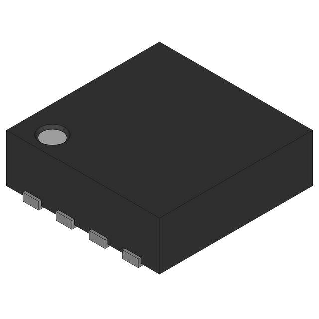
DRB Package
(Top View)
VC1
1
8
OUT
VC2
2
7
VDD
VC3
3
6
CD
GND
4
5
VC4
P0012-02
1
Please be aware that an important notice concerning availability, standard warranty, and use in critical applications of
Texas Instruments semiconductor products and disclaimers thereto appears at the end of this data sheet.
PRODUCTION DATA information is current as of publication date.
Products conform to specifications per the terms of the Texas
Instruments standard warranty. Production processing does not
necessarily include testing of all parameters.
Copyright © 2010, Texas Instruments Incorporated
�bq29440, bq2944L0
bq29441, bq29442, bq29443, bq29449, bq2944L9
SLUSA15C – JUNE 2010 – REVISED NOVEMBER 2010
www.ti.com
These devices have limited built-in ESD protection. The leads should be shorted together or the device placed in conductive foam
during storage or handling to prevent electrostatic damage to the MOS gates.
Table 1. ORDERING INFORMATION (1)
PART
NUMBER
TA
–40°C
to
+110°C
(1)
(2)
(3)
(4)
OUT PIN
LATCH
OPTION
PACKAGE
PACKAGE
DESIGNATOR
PACKAGE
MARKING
ORDERING INFORMATION (2)
OVP
TAPE AND REEL
(LARGE) (3)
TAPE AND REEL
(SMALL) (4)
BQ29440
No
440
4.35 V
BQ29440DRBR
BQ29440DRBT
BQ2944L0
Yes
44L0
4.35 V
BQ2944L0DRBR
BQ2944L0DRBT
BQ29441
No
BQ29442
No
BQ29443
No
QFN-8
DRB
441
4.40 V
BQ29441DRBR
BQ29441DRBT
442
4.45 V
BQ29442DRBR
BQ29442DRBT
443
4.50 V
BQ29443DRBR
BQ29443DRBT
BQ29449
No
449
4.30 V
BQ29449DRBR
BQ29449DRBT
BQ2944L9
Yes
44L9
4.30 V
BQ2944L9DRBR
BQ2944L9DRBT
Example: bq2944L0DRBR is a device with the OUT latch option with a VOV threshold of 4.35 V.
Contact Texas Instruments for other VOV threshold options.
For the most current package and ordering information, see the Package Addendum at the end of this document, or the TI website at
www.ti.com.
Large tape and reel quantity is 3,000 units.
Small tape and reel quantity is 250 units.
THERMAL INFORMATION
bq2944x
THERMAL METRIC (1)
DRB
UNITS
8 PINS
Junction-to-ambient thermal resistance (2)
qJA
50.5
(3)
qJC(top)
Junction-to-case(top) thermal resistance
qJB
Junction-to-board thermal resistance (4)
19.3
yJT
Junction-to-top characterization parameter (5)
0.7
yJB
Junction-to-board characterization parameter (6)
18.9
qJC(bottom)
Junction-to-case(bottom) thermal resistance (7)
5.2
(1)
(2)
(3)
(4)
(5)
(6)
(7)
25.1
°C/W
For more information about traditional and new thermal metrics, see the IC Package Thermal Metrics application report, SPRA953.
The junction-to-ambient thermal resistance under natural convection is obtained in a simulation on a JEDEC-standard, high-K board, as
specified in JESD51-7, in an environment described in JESD51-2a.
The junction-to-case (top) thermal resistance is obtained by simulating a cold plate test on the package top. No specific JEDECstandard test exists, but a close description can be found in the ANSI SEMI standard G30-88.
The junction-to-board thermal resistance is obtained by simulating in an environment with a ring cold plate fixture to control the PCB
temperature, as described in JESD51-8.
The junction-to-top characterization parameter, yJT, estimates the junction temperature of a device in a real system and is extracted
from the simulation data for obtaining qJA, using a procedure described in JESD51-2a (sections 6 and 7).
The junction-to-board characterization parameter, yJB, estimates the junction temperature of a device in a real system and is extracted
from the simulation data for obtaining qJA , using a procedure described in JESD51-2a (sections 6 and 7).
The junction-to-case (bottom) thermal resistance is obtained by simulating a cold plate test on the exposed (power) pad. No specific
JEDEC standard test exists, but a close description can be found in the ANSI SEMI standard G30-88.
PIN FUNCTIONS
2
PIN NAME
PIN NO.
CD
6
Connection to external capacitor for programmable delay time
DESCRIPTION
GND
4
Ground pin
OUT
8
Output
VC1
1
Sense voltage input for top cell
VC2
2
Sense voltage input for second-to-top cell
VC3
3
Sense voltage input for third-to-top cell
VC4
5
Sense voltage input for fourth-to-top cell (bottom cell)
VDD
7
Power supply
Submit Documentation Feedback
Copyright © 2010, Texas Instruments Incorporated
Product Folder Link(s): bq29440 bq2944L0 bq29441 bq29442 bq29443 bq29449 bq2944L9
�Not Recommended for New Designs
bq29440, bq2944L0
bq29441, bq29442, bq29443, bq29449, bq2944L9
www.ti.com
SLUSA15C – JUNE 2010 – REVISED NOVEMBER 2010
FUNCTIONAL BLOCK DIAGRAM
RVD
CVD
VDD
RIN
VC1
ICD
CIN
RIN
VC2
CIN
RIN
VC3
OUT
CIN
RIN
VC4
VCD
CIN
GND
CD
CCD
B0394-01
ABSOLUTE MAXIMUM RATINGS (1)
over operating free-air temperature range (unless otherwise noted)
VALUE/UNIT
Supply voltage range, VMAX
Input voltage range, VIN
Output voltage range, VOUT
VDD–GND
–0.3 to 28 V
VC1–GND, VC2–GND, VC3–GND
–0.3 to 28 V
VC1–VC2, VC2–VC3, VC3–VC4, VC4–GND
–0.3 to 8 V
CD–GND
–0.3 to 8 V
OUT–GND
–0.3 to 28 V
Storage temperature range, Tstg
(1)
–65°C to 150°C
Stresses beyond those listed under Absolute Maximum Ratings may cause permanent damage to the device. These are stress ratings
only and functional operation of the device at these or any other conditions beyond those indicated under Recommended Operating
Conditions is not implied. Exposure to absolute-maximum-rated conditions for extended periods may affect device reliability.
RECOMMENDED OPERATING CONDITIONS
MIN
Supply voltage, VDD
Input voltage range
VC1–VC2, VC2–VC3, VC3–VC4, VC4–GND
td(CD) delay-time capacitance
CCD (See Figure 7.)
Voltage monitor filter resistance
RIN (See Figure 7.)
Copyright © 2010, Texas Instruments Incorporated
MAX
UNIT
4
25
V
0
5
V
0.1
NOM
0.1
µF
1
kΩ
Submit Documentation Feedback
Product Folder Link(s): bq29440 bq2944L0 bq29441 bq29442 bq29443 bq29449 bq2944L9
3
�bq29440, bq2944L0
bq29441, bq29442, bq29443, bq29449, bq2944L9
SLUSA15C – JUNE 2010 – REVISED NOVEMBER 2010
www.ti.com
RECOMMENDED OPERATING CONDITIONS (continued)
MIN
NOM
Voltage monitor filter capacitance
CIN (See Figure 7.)
0.01
0.1
Supply voltage filter resistance
RVD (See Figure 7.)
0.1
Supply voltage filter capacitance
CVD (See Figure 7.)
Operating ambient temperature range, TA
MAX
UNIT
1
kΩ
µF
0.1
–40
µF
110
°C
ELECTRICAL CHARACTERISTICS
Typical values stated where TA = 25°C and VDD = 17 V, MIN/MAX values stated where TA = –40°C to 110°C and VDD = 4 V
to 25 V (unless otherwise noted).
PARAMETER
VPROTECT
TEST CONDITION
MIN
NOM
bq29440
4.35
bq29441
Overvoltage
detection
bq29442
voltage
bq29443
4.40
bq29449
4.30
MAX
4.45
UNIT
V
4.50
VHYS
Overvoltage detection
hysteresis
For non-latch devices only
200
VOA
Overvoltage detection
accuracy
TA = 25°C
VOA_DRIFT
Overvoltage threshold
temperature drift
XDELAY
TA = 0°C to 60°C
Overvoltage delay time Note: Does not include external capacitor variation
scale factor
TA = –40°C to 110°C
Note: Does not include external capacitor variation
300
400
mV
–10
10
mV
TA = 0°C to 60°C
–0.4
0.4
TA = –40°C to 110°C
–0.6
0.6
6.0
9.0
12
5.5
9.0
13.5
mV/°C
s/µF
XDELAY_CTM
Overvoltage delay time
scale factor in
See CUSTOMER TEST MODE.
Customer Test Mode
0.08
s/µF
ICD(CHG)
Overvoltage detection
charging current
See Figure 1.
140
nA
ICD(DSG)
Overvoltage detection
discharging current
See Figure 2.
60
µA
VCD
Overvoltage detection
external capacitor
comparator threshold
1.2
V
ICC
Supply current
VOUT
OUT pin drive voltage
(VC1–VC2), (VC2–VC3), (VC3–VC4) and (VC4–GND) =
3.5 V
See Figure 3.
2
3.5
µA
9.5
V
(VC1–VC2), (VC2–VC3), (VC3–VC4) or
(VC4–GND) = VPROTECT, VDD = 20 V,
IOH = 0 to –10 µA
6.5
8.0
(VC1–VC2), (VC2–VC3), (VC3–VC4) or
(VC4–GND) = VPROTECT, VDD = 4.35 V,
IOL = –10 µA, TA = 0°C to 60°C
1.50
3.0
V
(VC1–VC2), (VC2–VC3), (VC3–VC4) or
(VC4–GND) = VPROTECT, VDD > 6 V,
IOH = –10 µA, TA = 0°C to 60°C
2.0
3.0
V
(VC1–VC2), (VC2–VC3), (VC3–VC4) or
(VC4–GND) = 4 V, IOL = 0 µA
OUT short circuit
current
OUT = 0 V, (VC1–VC2), (VC2–VC3), (VC3–VC4) or
(VC4–GND) > VPROTECT, VDD = 18 V
tr(OUT) (1)
OUT output rise time
CL = 1 nF, VDD = 4 V to 25 V, VOH(OUT) = 0 V to 5 V
ZO(OUT) (1)
OUT output impedance
IOUT(SHORT)
(1)
4
0.1
V
4
mA
5
µs
2
kΩ
Specified by design. Not 100% tested in production.
Submit Documentation Feedback
Copyright © 2010, Texas Instruments Incorporated
Product Folder Link(s): bq29440 bq2944L0 bq29441 bq29442 bq29443 bq29449 bq2944L9
�bq29440, bq2944L0
bq29441, bq29442, bq29443, bq29449, bq2944L9
www.ti.com
SLUSA15C – JUNE 2010 – REVISED NOVEMBER 2010
ELECTRICAL CHARACTERISTICS (continued)
Typical values stated where TA = 25°C and VDD = 17 V, MIN/MAX values stated where TA = –40°C to 110°C and VDD = 4 V
to 25 V (unless otherwise noted).
PARAMETER
Input current at VCx
pins
IIN
TEST CONDITION
MIN
Measured at VC1, (VC1–VC2), (VC2–VC3), (VC3–VC4) and
(VC4–GND) = 3.5 V, TA = 0°C to 60°C
See Figure 3.
Measured at VC2, VC3 OR VC4, (VC1–VC2), (VC2–VC3),
(VC3–VC4) and (VC4–GND) = 3.5 V, TA = 0°C to 60°C
See Figure 3.
NOM
MAX
UNIT
–0.3
1.5
µA
–0.3
0.3
µA
TYPICAL CHARACTERISTICS
ICD CHARGE CURRENT
vs
TEMPERATURE
ICD DISCHARGE CURRENT
vs
TEMPERATURE
-80
80
-90
75
-100
ICD Discharge Current (µA)
ICD Charge Current (nA)
70
-110
-120
-130
-140
-150
65
60
55
50
-160
45
-170
-180
-40
-20
0
20
40
60
Temperature (°C)
80
40
-40
100
-20
0
20
40
60
Temperature (°C)
80
100
G001
G002
Figure 1. ICD Charge Current
Figure 2. ICD Discharge Current
ICC
IIN
1
VC1
OUT
8
IIN
2
VC2
VDD
7
IIN
3
VC3
CD
6
4
GND
VC4
5
IIN
Figure 3. ICC, IIN Measurement
Copyright © 2010, Texas Instruments Incorporated
Submit Documentation Feedback
Product Folder Link(s): bq29440 bq2944L0 bq29441 bq29442 bq29443 bq29449 bq2944L9
5
�bq29440, bq2944L0
bq29441, bq29442, bq29443, bq29449, bq2944L9
SLUSA15C – JUNE 2010 – REVISED NOVEMBER 2010
www.ti.com
APPLICATIONS INFORMATION
PROTECTION (OUT) TIMING AND DELAY TIME CAPACITOR SIZING
The bq2944x uses an external capacitor to set delay timing during an overvoltage condition. When any of the
cells exceed the overvoltage threshold, the bq2944x activates an internal current source of nominally 140 nA,
which charges the external capacitor. When the external capacitor charges up to a voltage of nominally 1.2 V,
the OUT pin transitions from a low state to a high state, by means of an internal pull-up network, to a regulated
voltage of no more than 9.5 V when IOH = 0 mA.
Cell Voltage
VC1–VC2
VC2–VC3
VC3–VC4
VC4–GND
VPROTECT
VPROTECT – VHYS
td
L
OUT
H
T0461-01
Figure 4. Timing for Overvoltage Sensing
Sizing the external capacitor is based on the desired delay time as follows:
CCD =
td
XDELAY
Where td is the desired delay time and xDELAY is the overvoltage delay time scale factor, expressed in seconds
per microFarad. xDELAY is nominally 9.0 s/µF. For example, if a nominal delay of 3 seconds is desired, the
customer should use a CCD capacitor that is 3 s/9.0 s/µF = 0.33 µF.
The delay time is calculated as follows:
t d = CCD ´ XDELAY
If the cell overvoltage condition is removed before the external capacitor reaches the reference voltage, the
internal current source is disabled and an internal discharge block is employed to discharge the external
capacitor down to 0 V. In this instance, the OUT pin remains in a low state.
For latched versions of the bq2944x, if an overvoltage condition has caused the OUT pin to transition to a high
state, the external capacitor remains charged even after the overvoltage condition has been removed. In this
instance, the OUT pin remains in a high state.
For non-latched versions, the OUT pin is allowed to transition back from a high to low state when the overvoltage
condition is no longer present, and the external capacitor is discharged down to 0 V.
6
Submit Documentation Feedback
Copyright © 2010, Texas Instruments Incorporated
Product Folder Link(s): bq29440 bq2944L0 bq29441 bq29442 bq29443 bq29449 bq2944L9
�bq29440, bq2944L0
bq29441, bq29442, bq29443, bq29449, bq2944L9
www.ti.com
SLUSA15C – JUNE 2010 – REVISED NOVEMBER 2010
BATTERY CONNECTION FOR 2-SERIES, 3-SERIES, AND 4-SERIES CELL CONFIGURATIONS
Figure 5, Figure 6, and Figure 7 show the 2-series, 3-series, and 4-series cell configurations.
RVD
1
VC1
OUT
8
2
VC2
VDD
7
3
VC3
CD
6
4
GND
VC4
5
CVD
RIN
CIN
RIN
CIN
CCD
Figure 5. 2-Series Cell Configuration
RVD
RIN
1
VC1
OUT
8
2
VC2
VDD
7
3
VC3
CD
6
4
GND
VC4
5
CIN
RIN
CIN
RIN
CIN
CVD
CCD
Figure 6. 3-Series Cell Configuration
RVD
RIN
CIN
RIN
CIN
RIN
CIN
RIN
CIN
1
VC1
OUT
8
2
VC2
VDD
7
3
VC3
CD
6
4
GND
VC4
5
CVD
CCD
Figure 7. 4-Series Cell Configuration
Copyright © 2010, Texas Instruments Incorporated
Submit Documentation Feedback
Product Folder Link(s): bq29440 bq2944L0 bq29441 bq29442 bq29443 bq29449 bq2944L9
7
�bq29440, bq2944L0
bq29441, bq29442, bq29443, bq29449, bq2944L9
SLUSA15C – JUNE 2010 – REVISED NOVEMBER 2010
www.ti.com
CELL CONNECTION SEQUENCE
NOTE
Before connecting the cells, propagate the overvoltage delay timing capacitor, CCD.
The recommended cell connection sequence begins from the bottom of the stack, as follows:
1. GND
2. VC4
3. VC3
4. VC2
5. VC1
While not advised, connecting the cells in a sequence other than that described above does not result in errant
activity on the OUT pin. For example:
1. GND
2. VC4, VC3, VC2, or VC1
3. Remaining VCx pin
4. Remaining VCx pin
5. Remaining VCx pin
CUSTOMER TEST MODE
Customer Test Mode (CTM) helps to greatly reduce the overvoltage detection delay time and enable quicker
customer production testing. This mode is intended for quick-pass board-level verification tests, and, as such,
individual cell overvoltage levels may deviate slightly from the specifications (VPROTECT, VOA). If accurate
overvoltage thresholds are to be tested, use the standard delay settings that are intended for normal use.
To enter CTM, VDD should be set to approximately 9.5 V higher than VC1. When CTM is entered, the device
switches from the normal overvoltage delay time scale factor, xDELAY, to a significantly reduced factor, xDELAY_CTM,
thereby reducing the delay time during an overvoltage condition. The CTM overvoltage delay time is similar to
the equation presented in PROTECTION (OUT) TIMING AND DELAY TIME CAPACITOR SIZING with the
substitution of xDELAY_CTM in place of xDELAY:
t d _ CTM = CCD ´ XDELAY_CTM
CAUTION
Avoid exceeding any Absolute Maximum Voltages on any pins when placing the part
into Customer Test Mode. Also, avoid exceeding Absolute Maximum Voltages for the
individual cell voltages (VC1–VC2), (VC2–VC3), (VC3–VC4), and (VC4–GND).
Stressing the pins beyond the rated limits may cause permanent damage to the
device.
To exit CTM, power off the device and then power it back on.
For latched versions of the bq2944x, the external CCD capacitor must be externally discharged if any overvoltage
functionality is exercised during protection testing. This can be accomplished by shorting the CD pin to GND. If
the CCD capacitor is not explicitly discharged, a residual charge may cause the overvoltage delay time to be
inaccurate.
8
Submit Documentation Feedback
Copyright © 2010, Texas Instruments Incorporated
Product Folder Link(s): bq29440 bq2944L0 bq29441 bq29442 bq29443 bq29449 bq2944L9
�bq29440, bq2944L0
bq29441, bq29442, bq29443, bq29449, bq2944L9
www.ti.com
SLUSA15C – JUNE 2010 – REVISED NOVEMBER 2010
REVISION HISTORY
Changes from Revision B (June 2010) to Revision C
Page
•
Added new protection thresholds ......................................................................................................................................... 1
•
Changed occurrences of VDD to VDD throughout document ................................................................................................ 1
•
Added part numbers ............................................................................................................................................................. 2
•
Changed the Functional Block Diagram ............................................................................................................................... 3
•
Changed the Electrical Characteristics ................................................................................................................................. 4
•
Deleted 3.5 from one of the maximum values from the VOUT specification .......................................................................... 4
•
Changed nominal delay time ................................................................................................................................................ 6
Copyright © 2010, Texas Instruments Incorporated
Submit Documentation Feedback
Product Folder Link(s): bq29440 bq2944L0 bq29441 bq29442 bq29443 bq29449 bq2944L9
9
�PACKAGE OPTION ADDENDUM
www.ti.com
10-Dec-2020
PACKAGING INFORMATION
Orderable Device
Status
(1)
Package Type Package Pins Package
Drawing
Qty
Eco Plan
(2)
Lead finish/
Ball material
MSL Peak Temp
Op Temp (°C)
Device Marking
(3)
(4/5)
(6)
BQ29440DRBR
ACTIVE
SON
DRB
8
3000
RoHS & Green
NIPDAU
Level-2-260C-1 YEAR
-40 to 85
440
BQ29440DRBT
ACTIVE
SON
DRB
8
250
RoHS & Green
NIPDAU
Level-2-260C-1 YEAR
-40 to 85
440
BQ29441DRBR
ACTIVE
SON
DRB
8
3000
RoHS & Green
NIPDAU
Level-2-260C-1 YEAR
-40 to 85
441
BQ29441DRBT
ACTIVE
SON
DRB
8
250
RoHS & Green
NIPDAU
Level-2-260C-1 YEAR
-40 to 85
441
BQ29442DRBR
ACTIVE
SON
DRB
8
3000
RoHS & Green
NIPDAU
Level-2-260C-1 YEAR
-40 to 85
442
BQ29442DRBT
ACTIVE
SON
DRB
8
250
RoHS & Green
NIPDAU
Level-2-260C-1 YEAR
-40 to 85
442
BQ29443DRBR
ACTIVE
SON
DRB
8
3000
RoHS & Green
NIPDAU
Level-2-260C-1 YEAR
-40 to 85
443
BQ29443DRBT
ACTIVE
SON
DRB
8
250
RoHS & Green
NIPDAU
Level-2-260C-1 YEAR
-40 to 85
443
BQ29449DRBR
ACTIVE
SON
DRB
8
3000
RoHS & Green
NIPDAU
Level-2-260C-1 YEAR
-40 to 85
449
BQ29449DRBT
ACTIVE
SON
DRB
8
250
RoHS & Green
NIPDAU
Level-2-260C-1 YEAR
-40 to 85
449
(1)
The marketing status values are defined as follows:
ACTIVE: Product device recommended for new designs.
LIFEBUY: TI has announced that the device will be discontinued, and a lifetime-buy period is in effect.
NRND: Not recommended for new designs. Device is in production to support existing customers, but TI does not recommend using this part in a new design.
PREVIEW: Device has been announced but is not in production. Samples may or may not be available.
OBSOLETE: TI has discontinued the production of the device.
(2)
RoHS: TI defines "RoHS" to mean semiconductor products that are compliant with the current EU RoHS requirements for all 10 RoHS substances, including the requirement that RoHS substance
do not exceed 0.1% by weight in homogeneous materials. Where designed to be soldered at high temperatures, "RoHS" products are suitable for use in specified lead-free processes. TI may
reference these types of products as "Pb-Free".
RoHS Exempt: TI defines "RoHS Exempt" to mean products that contain lead but are compliant with EU RoHS pursuant to a specific EU RoHS exemption.
Green: TI defines "Green" to mean the content of Chlorine (Cl) and Bromine (Br) based flame retardants meet JS709B low halogen requirements of