SWRU284A
October 2015
CC1101-CC1190EMK Quick Start Guide
Opening the box and using the modules with SmartRF04EB
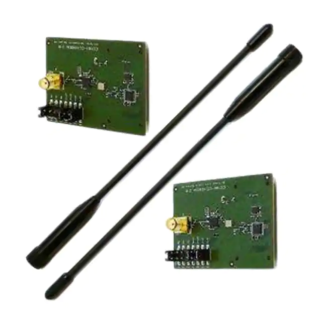
1. Kit Contents
2 x CC1101-CC1190EM (869 or 915 MHz)
2 x Pulse W5017 Antennas (2 dBi)
The 869 MHz RF boards are designed to comply with
relevant ETSI regulatory requirements over temperatures
from 0 to +35°C. The 915 MHz RF boards are designed
to comply with relevant FCC and IC regulatory
requirements over temperatures from 0 to +35°C.
The boards should not be modified to operate in other
frequency bands than what they have been designed for.
4a. Apply Power
2. How to Use the Modules
3. Plug EM into SmartRF04EB
The CC1101-CC1190 Evaluation Module
(EM) boards can be plugged into the
SmartRF04EB (EB), which is included in
the CC1101DK. This board lets you control
the devices from SmartRF™ Studio and it
can also be used as a development
platform.
The evaluation module is also supported
by the SmartRF TrxEB, included in the
CC11xL,
CC1120
and
CC1200
development kits.
This Quick Start Guide describes how to
properly power the SmartRF04EB with a
CC1101-CC1190EM and how to control
the combo from SmartRF Studio.
4b. Power the EB
Insert the EM into the EB. Attach the antenna
firmly.
Caution! Due to potential high output power from
the device, please keep a distance of at least 20
cm between the user and the antenna.
Caution! The kit contains ESD sensitive
components. Handle with care to prevent
permanent damage.
4c. Power the EM
The EB can be powered from different
sources: USB, Battery or an External
Power Supply
The voltage regulator on the EB supplies
3.3 V to the assembly, but it can only
source up to 150 mA. It cannot supply the Connect the EB to a USB port on a PC.
CC1101-CC1190EM since it can consume
more than 300 mA. An external power
supply is therefore required for powering
the EM.1
It is possible to have separate power
sources for the EB and for the EM. This is
controlled with the strap between I_OUT
and I_IN on P5 (the screw terminal).
Remove it to allow separate power
supplies.
4d. Optional: Same Power
Supply for both EB and EM
As noted in 4a, remove the strap on P5
and connect the external power supply as
shown in the picture above. The red wire is
the positive supply and the black wire is
GND.
Alternatively, connect a 9 Volt, nonrechargeable, alkaline battery to the This will power the EM directly from the
battery connector on the bottom side of the external power supply, whereas the rest of
board.
the EB will be powered from USB or the
battery.
Note that if multiple power sources are
connected, the source with the highest The power supply range should be within
voltage will power the EB. This means that 3.0 to 3.6 V.
you should disconnect any attached
battery when using USB power; otherwise
the battery will be drained.
5. Set Power Switch
6. External Power Supply Range
With the test setup in 4a-4c, the EB is
connected to a 3.3 V supply through the
on-board voltage regulator and the EM is
powered by the external supply. Since the
EB is powered through a regulated 3.3 V
supply the signals going from CC1101If EB and EM are powered from different CC1190 to the EB (and vice versa) need to
sources as described in 4a-4c, the switch be within 3.0 V to 3.6 V. The external
supply connected to the EM when using
should be set to the rightmost position.
the setup in 4a-4c is therefore limited to 3.0
GND
VDD
If EB and EM are powered from the same V to 3.6 V.
Connect a 3.3 V voltage source between external supply as described in 4d, the With the setup in 4d the supply range is
the 3.3 V and 0 V terminals. 3.3 V is the switch should be set to the leftmost limited 2.7 V to 3.6 V.
position.
middle terminal.
In this case, the on-board voltage regulator This switch can be used to turn off the EB
will be bypassed. Note that the strap on P5 by switching it to the opposite position of
that used to turn it on.
should not be removed.
1
External Power Supply2 Requirements:
Nom Voltage: 3.3VDC
Max Current: 800 mA
Efficiency Level V
Note that this is not the case for the SmartRFTrxEB.
When using an external power supply, make sure it meets the listed requirements in addition to complying with applicable regional product regulatory and safety certification
requirements such as UL, CSA, VDE, CCC, and PSE
2
�SWRU284A
October 2015
SmartRF™ Studio
1. Download and Install SmartRF Studio
2. Launch SmartRF Studio
Before connecting the EB to your PC, download SmartRF™
Studio from www.ti.com/smartrfstudio.
Install the program and follow the instructions in the wizard.
Connect the EB with a CC1101-CC1190EM to the PC using
the USB cable and install the USB driver as described in the
manual.
Launch SmartRF Studio and double click on the highlighted
CC1101 device icon to get complete control of the device from
the PC.
You can now configure the radio, run tests, export register
settings and run link tests with another CC1101-CC1190EM on
a SmartRF04EB (or SmartRF TrxEB) connected to the PC.
3. Configure the Radio
In order to control the CC1190 select CC1190 as “Range Extender” and select the appropriate “EM Revisions” as shown (either
869 or 915 MHz). You can now use all the features in Studio as for a standalone EM. Test the performance of the radio using
some of these features:
Continuous TX: Output power, spectrum
Continuous RX: Received signal strength, synchronous/asynchronous serial RX mode
Packet TX/RX: Link and sensitivity testing
References
Please visit
http://www.ti.com/product/cc1190
http://www.ti.com/tool/cc1101cc1190emk868
http://www.ti.com/tool/cc1101cc1190emk915
http://www.ti.com/lit/swra356 (Using the CC1190 Front End with CC1101 under EN 300 220)
http://www.ti.com/lit/swra361 (Using the CC1190 Front End with CC1101 under FCC 15.247)
Download the SmartRF™ Studio software, as well as datasheets, reference designs and application notes.
You will also find a lot of information on the TI E2E forum at http://e2e.ti.com
We hope you will enjoy working with the CC1101 and CC1190 devices.
�IMPORTANT NOTICE
Texas Instruments Incorporated and its subsidiaries (TI) reserve the right to make corrections, enhancements, improvements and other
changes to its semiconductor products and services per JESD46, latest issue, and to discontinue any product or service per JESD48, latest
issue. Buyers should obtain the latest relevant information before placing orders and should verify that such information is current and
complete. All semiconductor products (also referred to herein as “components”) are sold subject to TI’s terms and conditions of sale
supplied at the time of order acknowledgment.
TI warrants performance of its components to the specifications applicable at the time of sale, in accordance with the warranty in TI’s terms
and conditions of sale of semiconductor products. Testing and other quality control techniques are used to the extent TI deems necessary
to support this warranty. Except where mandated by applicable law, testing of all parameters of each component is not necessarily
performed.
TI assumes no liability for applications assistance or the design of Buyers’ products. Buyers are responsible for their products and
applications using TI components. To minimize the risks associated with Buyers’ products and applications, Buyers should provide
adequate design and operating safeguards.
TI does not warrant or represent that any license, either express or implied, is granted under any patent right, copyright, mask work right, or
other intellectual property right relating to any combination, machine, or process in which TI components or services are used. Information
published by TI regarding third-party products or services does not constitute a license to use such products or services or a warranty or
endorsement thereof. Use of such information may require a license from a third party under the patents or other intellectual property of the
third party, or a license from TI under the patents or other intellectual property of TI.
Reproduction of significant portions of TI information in TI data books or data sheets is permissible only if reproduction is without alteration
and is accompanied by all associated warranties, conditions, limitations, and notices. TI is not responsible or liable for such altered
documentation. Information of third parties may be subject to additional restrictions.
Resale of TI components or services with statements different from or beyond the parameters stated by TI for that component or service
voids all express and any implied warranties for the associated TI component or service and is an unfair and deceptive business practice.
TI is not responsible or liable for any such statements.
Buyer acknowledges and agrees that it is solely responsible for compliance with all legal, regulatory and safety-related requirements
concerning its products, and any use of TI components in its applications, notwithstanding any applications-related information or support
that may be provided by TI. Buyer represents and agrees that it has all the necessary expertise to create and implement safeguards which
anticipate dangerous consequences of failures, monitor failures and their consequences, lessen the likelihood of failures that might cause
harm and take appropriate remedial actions. Buyer will fully indemnify TI and its representatives against any damages arising out of the use
of any TI components in safety-critical applications.
In some cases, TI components may be promoted specifically to facilitate safety-related applications. With such components, TI’s goal is to
help enable customers to design and create their own end-product solutions that meet applicable functional safety standards and
requirements. Nonetheless, such components are subject to these terms.
No TI components are authorized for use in FDA Class III (or similar life-critical medical equipment) unless authorized officers of the parties
have executed a special agreement specifically governing such use.
Only those TI components which TI has specifically designated as military grade or “enhanced plastic” are designed and intended for use in
military/aerospace applications or environments. Buyer acknowledges and agrees that any military or aerospace use of TI components
which have not been so designated is solely at the Buyer's risk, and that Buyer is solely responsible for compliance with all legal and
regulatory requirements in connection with such use.
TI has specifically designated certain components as meeting ISO/TS16949 requirements, mainly for automotive use. In any case of use of
non-designated products, TI will not be responsible for any failure to meet ISO/TS16949.
Products
Applications
Audio
www.ti.com/audio
Automotive and Transportation
www.ti.com/automotive
Amplifiers
amplifier.ti.com
Communications and Telecom
www.ti.com/communications
Data Converters
dataconverter.ti.com
Computers and Peripherals
www.ti.com/computers
DLP® Products
www.dlp.com
Consumer Electronics
www.ti.com/consumer-apps
DSP
dsp.ti.com
Energy and Lighting
www.ti.com/energy
Clocks and Timers
www.ti.com/clocks
Industrial
www.ti.com/industrial
Interface
interface.ti.com
Medical
www.ti.com/medical
Logic
logic.ti.com
Security
www.ti.com/security
Power Mgmt
power.ti.com
Space, Avionics and Defense
www.ti.com/space-avionics-defense
Microcontrollers
microcontroller.ti.com
Video and Imaging
www.ti.com/video
RFID
www.ti-rfid.com
OMAP Applications Processors
www.ti.com/omap
TI E2E Community
e2e.ti.com
Wireless Connectivity
www.ti.com/wirelessconnectivity
Mailing Address: Texas Instruments, Post Office Box 655303, Dallas, Texas 75265
Copyright © 2015, Texas Instruments Incorporated
�


 工商网监
湘ICP备2023018690号
工商网监
湘ICP备2023018690号