SWRU292A
January 2012
CC11xL 868/915 MHz Development Kit Quick Start Guide
Opening the Box and Running the Packet Error Rate Test
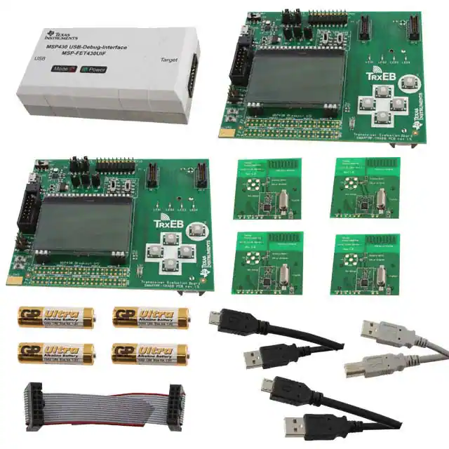
1. Kit Contents
2. TrxEB Overview
Power
Selection
EM
Breakout
3. Plug the EM into the TrxEB
Board Mode
Switches
EM
Connectors
Main
Power
Switch
USB
2 x SmartRF™ Transciever EB (TrxEB)
2 x CC110LEM 868/915 MHz
1 x CC113LEM 868/915 MHz
1 x CC115LEM 868/915 MHz
1 x MSP430 Debug Probe (FET)
2 x Micro USB Cables
1 x Standard USB Cable
1 x 14-pin Flat Cable
4 x 1.5 Volt AA Batteries
Documentation
Insert a CC110LEM into the TrxEB. The
connectors will only fit in one position so that the
EM cannot be inserted the wrong way. Do not
use excessive force on the EM.
MSP430
Debug
Interface
MSP430
Breakout
LCD
Buttons
LEDs
The EM has a PCB antenna, so there is no need
for an external antenna.
Caution! The kit contains ESD sensitive
components. Handle with care to
prevent
permanent
damage.
To
minimize risk of injury, avoid touching
components
during
operation
if
symbolized as hot.
4. Select Board Mode
5. Power Options
Use the switches S1 and S2 to select the
operating mode of the board. For the sake of this
quick start guide, please select “Enable” and
“UART”. This configuration will make it possible
to communicate directly with the MSP430 over a
virtual COM port on the PC.
There are several ways of applying power to the
TrxEB.
You can also use CC113L and CC115L for the
Per test, but note that CC113L is a receiver only
and CC115L is a transmitter only.
6. Select Power Source
2 x 1.5 V AA batteries
USB
External Power Supply
MSP430 Debugger
For the batteries and USB, there are voltage
regulators on the TrxEB that will set the on-board
voltage to 3.3 V. The external power supply
should set a voltage that does not exceed 3.3 V.
By default, the MSP430 debugger supplies 3.0 V.
Note that there should only be one active
power source at any one time.
Warning! To minimize risk of personal injury or
property damage, never use rechargeable
batteries to power the board. Do not leave the
EVM powered when unattended.
Depending on the power source, make sure
you connect jumpers to the appropriate pins
on the “Power Source” header. For instance,
if you use batteries, use a jumper to shortcircuit pin 1 and 2 on the header. The last
jumper in the row (pin 9-10) should always
be mounted, unless the MSP430 FET is
used as the power source.
7. Welcome Screen
8. Packet Error Rate Test
9. Select Test Mode
Turn on power with the Main Power switch. You
should now see the Texas Instruments logo and
a short description of the buttons on the LCD.
Pushing any of the five buttons on the board will
take you to the main menu.
Select the PER (Packet Error Rate) test by
highlighting the selection using the up/down
buttons. Confirm your selection by pressing
Enter (right button).
The PER test can be run is several modes. Easy
Mode sets up a one-way test and uses default
settings. This test is convenient for practical
range testing.
The other test modes are described in the
“Software Examples for CC112x, CC11xL and
CC1101 User’s Guide”.
NB! If you don’t see anything on the screen –
don’t panic. First, make sure the mode switches
are in the correct positions (see step 4 above).
Secondly, the first build of TrxEB unfortunately
uses a connector that doesn’t fit exactly to the
pins of the LCD. It should be sufficient to tilt the
LCD slightly to get a snug fit with the connector.
To proceed, highlight “Easy Mode” and press
Enter (right button).
Web sites:
E2E Forum:
www.ti.com/lprf
www.ti.com/lprf-forum
Make sure to subscribe to the Low-Power RF
Newsletter to receive information about updates to
documentation, new product releases, and more.
Sign up on the TI web pages.
�10. Select Frequency
11. Select Mode
12. Establish Link
One of the boards must operate as the slave
(transmitter) and the other as master (receiver).
Select Slave on one board…
The slave node will now wait for a configuration
package from the Master. The configuration
contains the parameters used for the PER test.
…and Master on the other board.
The configuration package will be sent when you
select “link devices” on the master node.
13. Link Established
14. Start the Receiver (master)
15. PER Test Results
When the initial linking has completed, the slave
node will start the test by continuously
transmitting packets to the master.
On the master node, you can select the number
of packets you want to receive in order to
calculate the packet error.
The master will display a window that plots the
received signal strength (RSSI) for each packet.
When selecting “Start PER Test”, the master
(receiver) will begin to count the number of
received packets and provide some statistics.
Press the “Up” button to go to the detailed
statistical window.
17. Troubleshooting
18. References
It you are experiencing problems with this test,
please check the following:
Please visit www.ti.com and
http://www.ti.com/tool/cc11xldk-868-915
Select which frequency to use for the test. Make
sure that the evaluation modules you have
match the selected frequency.
16. PER Test Results
The statistics window will show the error rate
based on the number of lost or erroneous
packets divided by the total number of packets
that should have been received.
Nothing is shown in the display!
Unfortunately, the first series of TrxEB uses
a connector that doesn’t fit exactly to the pins
of the LCD. It should be sufficient to tilt the
LCD slightly to get a snug fit with the
connector.
Please visit the kit web page and check for
updated SW and documentation. Updated
SW can be downloaded to the device using
IAR EW430 or SmartRF Flash Programmer.
If you get poor PER results at short
distances, try to move the transmitter and
receiver further apart. The CC11xL receiver
may experience saturation if it is too close to
the other CC11xL transmitting at full output
power.
On the kit product page, you will find additional
documentation, links to updated software
examples and software tools like SmartRF
Studio.
You will also find a lot of information on the TI
E2E forum at http://e2e.ti.com
We hope that you will enjoy working with the
CC110L, CC113L and CC115L devices.
SmartRF™ Studio
1. Download and Install
2. Launch SmartRF Studio
3. Test the Radio
Before connecting SmartRF TrxEB to your PC,
download and install SmartRF Studio from
www.ti.com/smartrfstudio.
After installing the tool, connect the EB to the PC
using the USB cable and start SmartRF Studio.
Select the “Sub 1 GHz” tab and double click the
highlighted device icon (CC110L, CC113L or
CC115L).
You can now configure the radio, export
register settings and run performance tests of
the radio.
�IMPORTANT NOTICE
Texas Instruments Incorporated and its subsidiaries (TI) reserve the right to make corrections, modifications, enhancements, improvements,
and other changes to its products and services at any time and to discontinue any product or service without notice. Customers should
obtain the latest relevant information before placing orders and should verify that such information is current and complete. All products are
sold subject to TI’s terms and conditions of sale supplied at the time of order acknowledgment.
TI warrants performance of its hardware products to the specifications applicable at the time of sale in accordance with TI’s standard
warranty. Testing and other quality control techniques are used to the extent TI deems necessary to support this warranty. Except where
mandated by government requirements, testing of all parameters of each product is not necessarily performed.
TI assumes no liability for applications assistance or customer product design. Customers are responsible for their products and
applications using TI components. To minimize the risks associated with customer products and applications, customers should provide
adequate design and operating safeguards.
TI does not warrant or represent that any license, either express or implied, is granted under any TI patent right, copyright, mask work right,
or other TI intellectual property right relating to any combination, machine, or process in which TI products or services are used. Information
published by TI regarding third-party products or services does not constitute a license from TI to use such products or services or a
warranty or endorsement thereof. Use of such information may require a license from a third party under the patents or other intellectual
property of the third party, or a license from TI under the patents or other intellectual property of TI.
Reproduction of TI information in TI data books or data sheets is permissible only if reproduction is without alteration and is accompanied
by all associated warranties, conditions, limitations, and notices. Reproduction of this information with alteration is an unfair and deceptive
business practice. TI is not responsible or liable for such altered documentation. Information of third parties may be subject to additional
restrictions.
Resale of TI products or services with statements different from or beyond the parameters stated by TI for that product or service voids all
express and any implied warranties for the associated TI product or service and is an unfair and deceptive business practice. TI is not
responsible or liable for any such statements.
TI products are not authorized for use in safety-critical applications (such as life support) where a failure of the TI product would reasonably
be expected to cause severe personal injury or death, unless officers of the parties have executed an agreement specifically governing
such use. Buyers represent that they have all necessary expertise in the safety and regulatory ramifications of their applications, and
acknowledge and agree that they are solely responsible for all legal, regulatory and safety-related requirements concerning their products
and any use of TI products in such safety-critical applications, notwithstanding any applications-related information or support that may be
provided by TI. Further, Buyers must fully indemnify TI and its representatives against any damages arising out of the use of TI products in
such safety-critical applications.
TI products are neither designed nor intended for use in military/aerospace applications or environments unless the TI products are
specifically designated by TI as military-grade or "enhanced plastic." Only products designated by TI as military-grade meet military
specifications. Buyers acknowledge and agree that any such use of TI products which TI has not designated as military-grade is solely at
the Buyer's risk, and that they are solely responsible for compliance with all legal and regulatory requirements in connection with such use.
TI products are neither designed nor intended for use in automotive applications or environments unless the specific TI products are
designated by TI as compliant with ISO/TS 16949 requirements. Buyers acknowledge and agree that, if they use any non-designated
products in automotive applications, TI will not be responsible for any failure to meet such requirements.
Following are URLs where you can obtain information on other Texas Instruments products and application solutions:
Products
Applications
Audio
www.ti.com/audio
Automotive and Transportation www.ti.com/automotive
Amplifiers
amplifier.ti.com
Communications and Telecom www.ti.com/communications
Data Converters
dataconverter.ti.com
Computers and Peripherals
www.ti.com/computers
DLP® Products
www.dlp.com
Consumer Electronics
www.ti.com/consumer-apps
DSP
dsp.ti.com
Energy and Lighting
www.ti.com/energy
Clocks and Timers
www.ti.com/clocks
Industrial
www.ti.com/industrial
Interface
interface.ti.com
Medical
www.ti.com/medical
Logic
logic.ti.com
Security
www.ti.com/security
Power Mgmt
power.ti.com
Space, Avionics and Defense
www.ti.com/space-avionics-defense
Microcontrollers
microcontroller.ti.com
Video and Imaging
www.ti.com/video
RFID
www.ti-rfid.com
OMAP Mobile Processors
www.ti.com/omap
Wireless Connectivity
www.ti.com/wirelessconnectivity
TI E2E Community Home Page
e2e.ti.com
Mailing Address: Texas Instruments, Post Office Box 655303, Dallas, Texas 75265
Copyright © 2012, Texas Instruments Incorporated
�


 工商网监
湘ICP备2023018690号
工商网监
湘ICP备2023018690号