CC3100MOD SimpleLink™ Wi-Fi® Network
Processor Module - BoosterPack Hardware
User's Guide
Literature Number: SWRU396B
December 2014 – Revised May 2018
�Contents
1
2
Introduction ......................................................................................................................... 4
1.1
CC3100 Module BoosterPack (CC3100MODBOOST) .............................................................. 4
1.2
What is Included .......................................................................................................... 4
1.3
FCC/IC Regulatory Compliance ........................................................................................ 4
Hardware Description ........................................................................................................... 5
2.1
Block Diagram ............................................................................................................ 6
2.2
Hardware Features....................................................................................................... 6
2.3
Connector and Jumper Descriptions
2.4
Power ...................................................................................................................... 8
2.5
Measure the CC3100 Current Drawn ................................................................................ 10
..................................................................................
.......................................................................................
3
Connecting to the PC Using EMUBOOST ..............................................................................
3.1
CC31XXEMUBOOST ..................................................................................................
3.2
Connecting the Boards .................................................................................................
3.3
Jumper Settings on the CC3100MODBOOST ......................................................................
3.4
Jumper Settings on the EMUBOOST ................................................................................
4
Connecting to a LaunchPad.................................................................................................
4.1
LaunchPad Current Limitation ........................................................................................
5
Additional Information ........................................................................................................
5.1
Design Files .............................................................................................................
5.2
Software..................................................................................................................
5.3
Hardware Change Log .................................................................................................
5.4
Known Limitations ......................................................................................................
Revision History ..........................................................................................................................
2.6
2
Performing Conducted Testing
Table of Contents
6
11
13
13
14
15
15
16
16
17
17
17
17
17
18
SWRU396B – December 2014 – Revised May 2018
Submit Documentation Feedback
Copyright © 2014–2018, Texas Instruments Incorporated
�www.ti.com
List of Figures
1
CC3100MOD BoosterPack Board With the CC3100MOD ............................................................. 4
2
CC3100MODBOOST Front Side
3
4
5
6
7
8
9
10
11
12
13
14
15
16
17
.......................................................................................... 5
CC3100MODBOOST Block Diagram ..................................................................................... 6
Signal Assignments.......................................................................................................... 7
3.3-V Power From MCU ................................................................................................... 9
Feed USB on the BoosterPack (if the LaunchPad Cannot Source 5 V on 20-Pin Connector) .................... 9
3.3-V Power From LDO ................................................................................................... 10
Feed USB on the BoosterPack (Always While Using the Onboard LDO) .......................................... 10
Low Current Measurement ................................................................................................ 11
Active Current Measurement ............................................................................................. 11
Connectors on the Board ................................................................................................. 12
Resistor Switch for Radiated versus Conducted Tests................................................................ 12
CC31XXEMUBOOST Board .............................................................................................. 13
Portable Devices ........................................................................................................... 14
The CC3100BOOST Connected to the EMUBOOST ................................................................ 15
CC3100MODBOOST Connected to MSP430F5529 LaunchPad .................................................... 16
Jumper Settings When Used With LaunchPad ........................................................................ 16
List of Tables
1
Push Buttons ................................................................................................................. 6
2
LEDs ........................................................................................................................... 7
3
Jumper Settings .............................................................................................................. 7
4
Outer Row Connectors ...................................................................................................... 8
5
Inner Row Connectors ...................................................................................................... 8
6
Ports Available on J6 ...................................................................................................... 14
7
Ports Available on J5 ...................................................................................................... 14
8
CC3100MODBOOST Jumper Settings .................................................................................. 15
9
EMUBOOST Jumper Settings
10
...........................................................................................
Hardware Change Log.....................................................................................................
SWRU396B – December 2014 – Revised May 2018
Submit Documentation Feedback
Copyright © 2014–2018, Texas Instruments Incorporated
List of Figures
15
17
3
�User's Guide
SWRU396B – December 2014 – Revised May 2018
CC3100MOD SimpleLink™ Wi-Fi® Network Processor
Module BoosterPack Hardware
1
Introduction
1.1
CC3100 Module BoosterPack (CC3100MODBOOST)
Add Wi-Fi to any low-cost, low-power microcontroller (MCU) for Internet of Things (IoT) applications using
the CC3100 Module BoosterPack (CC3100MODBOOST), which hosts the CC3100 module
(CC3100MOD). The CC3100MOD is FCC, IC, CE, and Wi-Fi certified. It integrates all protocols for Wi-Fi
and Internet, greatly minimizing host MCU software requirements. With built-in security protocols, the
CC3100MOD solution provides a robust and simple security experience. The CC3100MOD integrates the
serial flash, RF filter, crystal, and all required passive components.
This document explains the various configurations, usage, and versatility of the CC3100MODBOOST.
First, it can be connected to a TI MCU LaunchPad (provided examples for MSPEXP430F5529LP).
Second, it can be plugged into a CC31XXEMUBOOST board and connected to a PC for MCU emulation.
The CC3100MODBOOST firmware updates requires either the CC31XXEMUBOOST board, or the microcontroller over-the-air(OTA) software and access to a server. Finally, the exposed signals on the 20 pin
connector provide an interface to an additional microcontroller or platforms beyond TI's LaunchPads. The
CC3100MODBOOST is a complete platform solution, including various tools and software, sample
applications, user and programming guides, reference designs, and the TI E2E™ support community. Visit
the CC3100 Wiki page for design resources and example projects
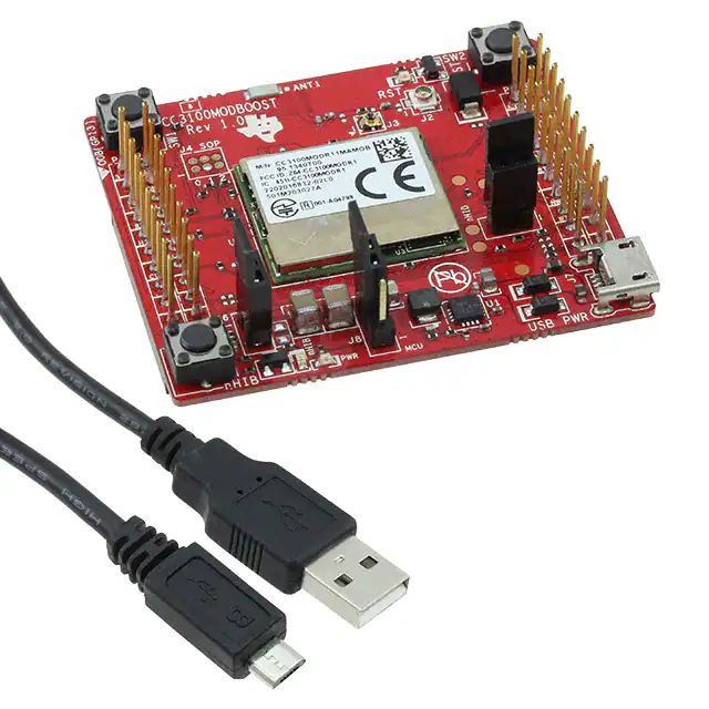
Figure 1. CC3100MOD BoosterPack Board With the CC3100MOD
1.2
What is Included
•
•
•
1.3
The CC3100MODBOOST board
One Micro USB cable
Quick Start guide
FCC/IC Regulatory Compliance
The CC3100MOD SimpleLink Wi-Fi and IoT Solution module is FCC Part 15 and IC ICES-003 Class A
Certified.
4
CC3100MOD SimpleLink™ Wi-Fi® Network Processor Module BoosterPack
Hardware
SWRU396B – December 2014 – Revised May 2018
Submit Documentation Feedback
Copyright © 2014–2018, Texas Instruments Incorporated
�Hardware Description
www.ti.com
2
Hardware Description
Figure 2. CC3100MODBOOST Front Side
SWRU396B – December 2014 – Revised May 2018
Submit Documentation Feedback
CC3100MOD SimpleLink™ Wi-Fi® Network Processor Module BoosterPack
Hardware
Copyright © 2014–2018, Texas Instruments Incorporated
5
�Hardware Description
2.1
www.ti.com
Block Diagram
Figure 3. CC3100MODBOOST Block Diagram
2.2
Hardware Features
•
•
•
•
•
•
•
•
2.3
2.3.1
CC3100MOD module with fully integrated solution
2×20 pin stackable connectors
Power from on-board LDO, using USB or 3.3 V from MCU LaunchPad
Three (3) push buttons
Jumper for current measurement with provision to mount 0.1R resistor for measurement with voltmeter
8 Mbit serial flash (M25PX80 from Micron)
40-MHz crystal, 32-KHz crystal, and optional 32-KHz oscillator
2-layer PCB with 6-mil spacing and track width
Connector and Jumper Descriptions
Push Buttons and LEDs
Table 1. Push Buttons
6
Reference
Usage
Comments
SW1
OOB Demo
Used as an input for the OOB demo.
SW2
RESET
Resets the device to a known state. The use of this pin is optional.
SW3
nHIB
Boots the device to the bootloader mode for flashing the firmware over a universal
asynchronous receiver/transmitter (UART).
CC3100MOD SimpleLink™ Wi-Fi® Network Processor Module BoosterPack
Hardware
SWRU396B – December 2014 – Revised May 2018
Submit Documentation Feedback
Copyright © 2014–2018, Texas Instruments Incorporated
�Hardware Description
www.ti.com
Table 2. LEDs
2.3.2
Reference
Color
Usage
Comments
D5
Red
PWR Indication
ON, when the 3.3-V power is provided to the board.
D1
Yellow
nRESET
This LED indicates the state of the nRESET pin. If this LED is glowing, the device
is functional.
D6
Green
nHIB
This LED indicates the state of the nHIB pin. When the LED is OFF, the device is
in hibernate state.
Jumper Settings
Table 3. Jumper Settings
2.3.3
Reference
Usage
Comments
J7
USB connector
For powering the booster pack when mated with a Launchpad. This is mandatory when using
“Z” devices. For example, CC3100HZ.
J8
Power selection
Choose the power supply from the Launchpad or the on-board USB.
J8 (1-2) power from MCU Launchpad
J8 (2-3) power from on-board USB using 3.3-V LDO
J6
Current
measurement
J5
OOB Demo
J10, J9
Booster pack
header
J3
RF Test
Murata connector (MM8030-2610) for production line tests.
J2
RF Test
U.FL connector for conducted testing in the lab.
For Hibernate and LPDS currents, connect an ammeter across J26 : Range (
很抱歉,暂时无法提供与“CC3100MODBOOST”相匹配的价格&库存,您可以联系我们找货
免费人工找货- 国内价格 香港价格
- 1+296.202221+38.30700
- 国内价格
- 1+662.28840
- 200+264.26520