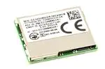
CC3100MOD
CC3100MOD
SWRS161B – NOVEMBER 2014 – REVISED SEPTEMBER
2020
SWRS161B – NOVEMBER 2014 – REVISED SEPTEMBER 2020
www.ti.com
CC3100MOD SimpleLink™ Wi-Fi CERTIFIED™ Network Processor Internet-of-Things
Module Solution for MCU Applications
1 Features
•
•
•
•
The CC3100MOD is a Wi-Fi® module consisting of
the CC3100R11MRGC Wi-Fi network processor
and power management subsystems. This fully
integrated module includes all required clocks,
serial peripheral interface (SPI) flash, and
passives.
Modular FCC, IC, TELEC, and CE certifications
save customer effort, time, and money
Wi-Fi CERTIFIED™ modules, with ability to request
certificate transfer for Wi-Fi Alliance members
Wi-Fi network processor subsystem
– Featuring Wi-Fi Internet-on-a chip™ circuits
– Dedicated Arm® microcontroller (MCU)
–
–
–
–
–
–
–
–
–
Completely offloads Wi-Fi and Internet
protocols from the external MCU
Wi-Fi driver and multiple Internet protocols in
ROM
802.11 b/g/n radio, baseband, and medium
access control (MAC), Wi-Fi driver, and
supplicant
TCP/IP stack
• Industry-standard BSD socket application
programming interfaces (APIs)
• 8 simultaneous TCP or UDP sockets
• 2 of the 8 sockets can be TLS and SSL
sockets
Powerful crypto engine for fast, secure Wi-Fi
and Internet connections with 256-bit AES
encryption for TLS and SSL connections
Station, AP, and Wi-Fi Direct® modes
WPA2 Personal and Enterprise Security
SimpleLink™ connection manager for
autonomous and fast Wi-Fi connections
SmartConfig™ technology, AP mode, and
WPS2 for easy and flexible Wi-Fi provisioning
TX power
• 17 dBm at 1 DSSS
• 17.25 dBm at 11 CCK
• 13.5 dBm at 54 OFDM
•
•
•
•
•
•
– RX sensitivity
• –94.7 dBm at 1 DSSS
• –87 dBm at 11 CCK
• –73 dBm at 54 OFDM
– Application throughput
• UDP: 16 Mbps
• TCP: 13 Mbps
Host interface
– Wide range of power supply (2.3 to 3.6 V)
– Interfaces with 8-, 16-, and 32-bit MCU or
ASICs over a SPI or UART interface
– Low footprint host driver: less than 6KB
– Supports RTOS and no-OS applications
Power-management subsystem
– Integrated DC-DC converter suports a wide
range of supply voltage:
• Direct battery mode: 2.3 V to 3.6 V
– Low power consumption at 3.6 V
• Hibernate with real-time clock (RTC): 7 μA
• Standby: 140 μA
• RX traffic: 54 mA at 54 OFDM
• TX traffic: 223 mA at 54 OFDM
Integrated components on module
– 40.0-MHz crystal with internal oscillator
– 32.768-kHz crystal (RTC)
– 8-Mbit SPI serial flash
– RF filter and passive components
1.27-mm pitch, 63-pin, 20.5-mm × 17.5-mm LGA
package for easy assembly and low-cost PCB
design
Operating temperature range: –20°C to +70°C
Module supports SimpleLink Developers
Ecosystem
An IMPORTANT NOTICE at the end of this data sheet addresses availability, warranty, changes, use in safety-critical applications,
Submit Document Feedback
Copyright
© 2020 Texas
Instruments
Incorporated
intellectual
property
matters
and other important disclaimers. PRODUCTION DATA.
Product Folder Links: CC3100MOD
1
�CC3100MOD
www.ti.com
SWRS161B – NOVEMBER 2014 – REVISED SEPTEMBER 2020
2 Applications
For Internet-of-Things (IoT) applications, such as:
• Cloud connectivity
• Internet gateway
• Home automation
• Home appliances
• Access control
•
•
•
•
•
•
•
Security systems
Smart energy
Industrial control
Smart plug and metering
Wireless audio
IP network sensor nodes
Wearables
3 Description
Add Wi-Fi® to low-cost, low-power MCU for IoT applications. The CC3100MOD is an FCC, IC, CE, and Wi-Fi
CERTIFIED™ module that is part of the SimpleLink™ Wi-Fi family, which dramatically simplifies the
implementation of Internet connectivity. The CC3100MOD integrates all protocols for Wi-Fi and Internet, which
greatly minimize host MCU software requirements. With built-in security protocols, the CC3100MOD solution
provides a robust and simple security experience. Additionally, the CC3100MOD is a complete platform solution
including various tools and software, sample applications, user and programming guides, reference designs, and
the TI E2E™ support community. The CC3100MOD is available in an LGA package that is easy to lay out with all
required components including serial Flash, RF filter, crystal, and passive components that are fully integrated.
The Wi-Fi network processor subsystem features Wi-Fi Internet-on-a chip™ circuitry and contains an additional
dedicated Arm® MCU that off-loads the host MCU. This subsystem includes an 802.11b/g/n radio, baseband,
and MAC with a powerful crypto engine for fast, secure Internet connections with 256-bit encryption. The
CC3100MOD module supports station, access point, and Wi-Fi direct modes. The module supports WPA2
personal and enterprise security and also WPS 2.0. This subsystem includes embedded TCP/IP, TLS/SSL
stacks, an HTTP server, and multiple Internet protocols.
The power-management subsystem includes an integrated DC-DC converter with support for a wide range of
supply voltages. This subsystem enables low-power consumption modes such as hibernate with RTC , which
requires approximately 7 µA. The CC3100MOD module can connect to any 8-, 16-, or 32-bit MCU over the SPI
or UART Interface. The device driver minimizes the host memory footprint requirements of less than 7KB of code
memory and 700B of RAM for a TCP client application.
Table 3-1. Module Information
PART NUMBER(1)
CC3100MODR11MAMOB
(1)
2
PACKAGE
BODY SIZE
MOB (63)
20.5 mm × 17.5 mm
For more information, see Section 13.
Submit Document Feedback
Copyright © 2020 Texas Instruments Incorporated
Product Folder Links: CC3100MOD
�CC3100MOD
www.ti.com
SWRS161B – NOVEMBER 2014 – REVISED SEPTEMBER 2020
4 Functional Block Diagrams
Figure 4-1 shows the functional block diagram of the CC3100MOD module.
32-KHz
Crystal
40-MHz
Crystal
Serial
Flash
8Mbit
VCC
CC3100R11MRGC
HOST I/F
RF Filter
Power
Inductors
Caps
Pull-up
resistors
CC3100MOD
Figure 4-1. CC3100MOD Functional Block Diagram
Submit Document Feedback
Copyright © 2020 Texas Instruments Incorporated
Product Folder Links: CC3100MOD
3
�CC3100MOD
www.ti.com
SWRS161B – NOVEMBER 2014 – REVISED SEPTEMBER 2020
RAM
Wi-Fi Driver
TCP/IP & TLS/SSL
Stacks
ROM
Crypto Engine
ARM Processor
MAC Processor
UART
DC-DC
BAT Monitor
Oscillators
LNA
SYSTEM
Synthesizer
PA
HOST I/F
SPI
Baseband
Radio
SWAS031-A
Figure 4-2. CC3100 Hardware Overview
User Application
SimpleLink Driver
SPI or UART Driver
External Microcontroller
Internet Protocols
TLS/SSL
Embedded Internet
TCP/IP
Supplicant
Wi-Fi Driver
Wi-Fi MAC
Embedded Wi-Fi
Wi-Fi Baseband
Wi-Fi Radio
ARM Processor (Wi-Fi Network Processor)
SWAS031-B
Figure 4-3. CC3100 Software Overview
4
Submit Document Feedback
Copyright © 2020 Texas Instruments Incorporated
Product Folder Links: CC3100MOD
�CC3100MOD
www.ti.com
SWRS161B – NOVEMBER 2014 – REVISED SEPTEMBER 2020
5 Functional Block Diagrams
Figure 5-1 shows the functional block diagram of the CC3100MOD module.
32-KHz
Crystal
40-MHz
Crystal
Serial
Flash
8Mbit
VCC
CC3100R11MRGC
HOST I/F
RF Filter
Power
Inductors
Caps
Pull-up
resistors
CC3100MOD
Figure 5-1. CC3100MOD Functional Block Diagram
Submit Document Feedback
Copyright © 2020 Texas Instruments Incorporated
Product Folder Links: CC3100MOD
5
�CC3100MOD
www.ti.com
SWRS161B – NOVEMBER 2014 – REVISED SEPTEMBER 2020
RAM
Wi-Fi Driver
TCP/IP & TLS/SSL
Stacks
ROM
Crypto Engine
ARM Processor
MAC Processor
UART
DC-DC
BAT Monitor
Oscillators
LNA
SYSTEM
Synthesizer
PA
HOST I/F
SPI
Baseband
Radio
SWAS031-A
Figure 5-2. CC3100 Hardware Overview
User Application
SimpleLink Driver
SPI or UART Driver
External Microcontroller
Internet Protocols
TLS/SSL
Embedded Internet
TCP/IP
Supplicant
Wi-Fi Driver
Wi-Fi MAC
Embedded Wi-Fi
Wi-Fi Baseband
Wi-Fi Radio
ARM Processor (Wi-Fi Network Processor)
SWAS031-B
Figure 5-3. CC3100 Software Overview
6
Submit Document Feedback
Copyright © 2020 Texas Instruments Incorporated
Product Folder Links: CC3100MOD
�CC3100MOD
www.ti.com
SWRS161B – NOVEMBER 2014 – REVISED SEPTEMBER 2020
Table of Contents
1 Features............................................................................1
2 Applications..................................................................... 2
3 Description.......................................................................2
4 Functional Block Diagrams............................................ 3
5 Functional Block Diagrams............................................ 5
6 Revision History.............................................................. 7
7 Terminal Configuration and Functions..........................9
7.1 CC3100MOD Pin Diagram..........................................9
7.2 Pin Attributes.............................................................10
8 Specifications................................................................ 12
8.1 Absolute Maximum Ratings...................................... 12
8.2 ESD Ratings............................................................. 12
8.3 Power-On Hours (POH)............................................ 12
8.4 Recommended Operating Conditions.......................12
8.5 Power Consumption Summary................................. 13
8.6 TX Power and IBAT versus TX Power Level
Settings....................................................................... 13
8.7 Brownout and Blackout Conditions........................... 15
8.8 Electrical Characteristics (3.3 V, 25°C)..................... 16
8.9 WLAN RF Characteristics......................................... 16
8.10 Reset Requirement................................................. 17
8.11 Thermal Resistance Characteristics for MOB
Package...................................................................... 17
8.12 Timing and Switching Characteristics..................... 18
8.13 Host UART..............................................................21
9 Detailed Description......................................................23
9.1 Overview................................................................... 23
9.2 Module Features....................................................... 23
9.3 Functional Block Diagram......................................... 23
9.4 Wi-Fi Network Processor Subsystem....................... 24
9.5 Power-Management Subsystem...............................25
9.6 Low-Power Operating Modes................................... 25
10 Applications, Implementation, and Layout............... 27
10.1 Reference Schematics............................................28
10.2 Design Requirements............................................. 29
10.3 Layout Recommendations...................................... 30
11 Environmental Requirements and Specifications.... 34
11.1 Temperature............................................................ 34
11.2 Handling Environment.............................................34
11.3 Storage Condition................................................... 34
11.4 Baking Conditions................................................... 34
11.5 Soldering and Reflow Condition..............................35
12 Device and Documentation Support..........................36
12.1 Device Support ...................................................... 36
12.2 Documentation Support.......................................... 36
12.3 Trademarks............................................................. 37
12.4 Electrostatic Discharge Caution..............................37
12.5 Glossary..................................................................37
13 Mechanical, Packaging, and Orderable
Information.................................................................... 38
13.1 Mechanical Drawing ...............................................38
13.2 Package Option...................................................... 40
6 Revision History
NOTE: Page numbers for previous revisions may differ from page numbers in the current version.
Changes from December 6, 2014 to September 22, 2020 (from Revision A () to Revision B ())
Page
• Updated the numbering format for tables, figures, and cross-references throughout the document..................1
• Updated and changed VBAT or Wide Voltage Mode to Direct Battery............................................................... 1
• Updated and changed featured VBAT range from "2.3 to 3.63 V" to "2.3 to 3.6 V"............................................1
• Changed TX current from 150 mA at 54OFDM to 223 mA at 54 OFDM ........................................................... 1
• Changed MODULE PIN DESCRIPTION for PIN NO. 47..................................................................................10
• Changed from Handling Ratings table to ESD Ratings table........................................................................... 12
• Deleted Reset Requirements table ..................................................................................................................13
• Added graphs representing TX Power and IBAT vs TX Power Level Settings (1 DSSS, 6 OFDM, and 54
OFDM).............................................................................................................................................................. 13
• Changed Brownout and Blackout Conditions section.......................................................................................15
• Added Electrical Characteristics ...................................................................................................................... 16
• Changed VOH in Electrical Characteristics (3.3 V, 25°C) ................................................................................. 16
• Changed VOL in Electrical Characteristics (3.3 V, 25°C) ................................................................................. 16
• Changed the Low-level sink current VOH value from: 0.4 to: 0.6 in Section 8.8 .............................................. 16
• Deleted VOH and VOL from the pullup and pulldown current entries in Section 8.8 ......................................... 16
• Changed Figure 8-8 .........................................................................................................................................19
• Changed minimum clock period to 50 ns, maximum clock low period to 25 ns, and maximum clock high
period to 25 ns in Host SPI Interface Timing Parameters ................................................................................19
• Changed minimum clock period to 50 ns, maximum clock low period to 25 ns, and maximum clock high
period to 25 ns in Host SPI Interface Timing Parameters ................................................................................19
Submit Document Feedback
Copyright © 2020 Texas Instruments Incorporated
Product Folder Links: CC3100MOD
7
�CC3100MOD
SWRS161B – NOVEMBER 2014 – REVISED SEPTEMBER 2020
•
•
•
•
•
•
•
•
•
•
•
•
•
•
•
•
•
•
8
www.ti.com
Added clock frequency at VBAT = 3.3 V and VBAT ≤ 2.1 V in Host SPI Interface Timing Parameters ........... 19
Added description for nHIB pin in Table 8-3 .................................................................................................... 20
Changed HOST_SPI_CLK from 24 MHz to 20 MHz in Table 8-3 ....................................................................20
Added Section 8.13, Host UART ..................................................................................................................... 21
Added Section 9.1, Overview .......................................................................................................................... 23
Changed Figure 9-1 .........................................................................................................................................23
Added Section 9.4, Wi-Fi Network Processor Subsystem ...............................................................................24
Added Table 9-1 ...............................................................................................................................................24
Changed in Section 9.5, Power Management Architecture ............................................................................. 25
Added Section 9.6, Low-Power Operating Modes ...........................................................................................25
Changed LPDS wakeup time from 10 ms to < 3 ms in Section 9.6.1, Low-Power Deep Sleep ...................... 25
Added Note 1 for Figure 10-1 .......................................................................................................................... 28
Changed the new Device and Documentation Support section....................................................................... 36
Added NOTE to Mechanical Drawing .............................................................................................................. 38
Updated reel quantities in Section 13.2 ........................................................................................................... 40
Changed Package Qty value for CC3100MODR11MAMOBR in Section 13.2.1 ............................................. 41
Changed SPQ value for CC3100MODR11MAMOBR throughout Section 13.2.2 ........................................... 42
Changed Pin1 Quadrant values in Section 13.2.2 ...........................................................................................42
Submit Document Feedback
Copyright © 2020 Texas Instruments Incorporated
Product Folder Links: CC3100MOD
�CC3100MOD
www.ti.com
SWRS161B – NOVEMBER 2014 – REVISED SEPTEMBER 2020
7 Terminal Configuration and Functions
7.1 CC3100MOD Pin Diagram
GND
27
NC
GND
NC
GND
RF_BG
GND
NC
SOP0
nRESET
VBAT_DCDC_ANA
VBAT_DCDC_PA
GND
NC
VBAT_DCDC_DIG_IO
NC
NC
GND
Figure 7-1 shows the pin diagram for the CC3100MOD device.
28
29
30
31
32
33
34
35
36
37
38
39
40
41
42
43
CC3100MOD
44
UART1_nRTS
26
45
NC
NC
25
46
UART1_TX
SOP1
24
47
UART1_RX
SOP2
23
48
TEST_58
NC
22
49
TEST_59
50
TEST_60
51
UART1_nCTS
52
TEST_62
53
NC
54
NC
RESERVED
21
NC
20
RESERVED
19
NC
18
GND
GND
63
62
61
GND
GND
60
59
58
GND
GND
56
17
GND
55
14
13
12
11
10
9
8
7
6
5
4
3
2
1
NC
NC
HOST_INTR
FORCE_AP
NC
HOST_SPI_nCS
HOST_SPI_DOUT
HOST_SPI_DIN
HOST_SPI_CLK
nHIB
NC
GND
GND
15
NC
16
NC
GND
GND
NC
57
Figure 7-1 shows the approximate location of pins on the module. For the actual mechanical diagram, refer to Section 13.
Figure 7-1. CC3100MOD Pin Diagram Bottom View
Submit Document Feedback
Copyright © 2020 Texas Instruments Incorporated
Product Folder Links: CC3100MOD
9
�CC3100MOD
www.ti.com
SWRS161B – NOVEMBER 2014 – REVISED SEPTEMBER 2020
7.2 Pin Attributes
Table 7-1 lists the pin descriptions of the CC3100MOD module.
Note
If an external device drives a positive voltage to signal pads when the CC3100MOD is not powered,
DC current is drawn from the other device. If the drive strength of the external device is adequate, an
unintentional wakeup and boot of the CC3100MOD can occur. To prevent current draw, TI
recommends one of the following:
• All devices interfaced to the CC3100MOD must be powered from the same power rail as the
CC3100MOD.
• Use level-shifters between the CC3100MOD and any external devices fed from other independent
rails.
• The nRESET pin of the CC3100MOD must be held low until the VBAT supply to the device is driven
and stable. Leaving the nRESET pin unconnected ensures this (_____) automatically due to the
internal RC circuit.
Table 7-1. Module Pin Attributes
PIN(1)
DEFAULT FUNCTION
TYPE
DESCRIPTION
1
GND
–
Ground
2
GND
–
Ground
3
NC
–
Reserved. Do not connect.
4
nHIB
I
Hibernate signal, active low. Refer to Figure 8-7.
5
HOST_SPI_CLK
I
Host interface SPI clock
6
HOST_SPI_DIN
I
Host interface SPI data input
7
HOST_SPI_DOUT
O
Host interface SPI data output
8
HOST_SPI_nCS
I
Host interface SPI chip select (active low)
9
NC
–
Reserved. Do not connect.
10
NC
–
Reserved. Do not connect.
11
HOST_INTR
O
Interrupt output
12
NC
–
Reserved. Do not connect.
13
FLASH_SPI_MISO
I
Serial flash interface: SPI data in (active high)
14
FLASH_SPI_nCS_IN
O
Serial flash interface: SPI chip select (active low)
15
FLASH_SPI_CLK
O
Serial flash interface: SPI clock
16
GND
–
Ground
17
FLASH_SPI_MOSI
O
Serial flash interface: SPI data out
18
NC
–
Reserved. Do not connect.
19
RESERVED
–
Reserved. Do not connect.
20
NC
–
Unused. Do not connect.
21
RESERVED
–
Add 100-kΩ external pulldown resistor. Not adding this resistor can lead to
higher current in LPDS mode.
SOP2/TCXO_EN
–
Add 10-kΩ pulldown to ground.
22
23
24
SOP1
–
Add 100k pulldown to ground.
25
NC
–
Reserved. Do not connect.
26
NC
–
Reserved. Do not connect.
GND
–
Ground
29
NC
–
Do not connect.
30
GND
–
Ground. Reference for RF signal.
27, 28
10
Submit Document Feedback
Copyright © 2020 Texas Instruments Incorporated
Product Folder Links: CC3100MOD
�CC3100MOD
www.ti.com
SWRS161B – NOVEMBER 2014 – REVISED SEPTEMBER 2020
Table 7-1. Module Pin Attributes (continued)
PIN(1)
31
DEFAULT FUNCTION
RF_BG
I/O
DESCRIPTION
2.4-GHz RF input/output
32
GND
–
Ground. Reference for RF signal.
33
NC
–
Reserved. Do not connect.
34
SOP0
–
Add 100k pulldown to ground.
35
nRESET
I
Power on reset. Does not require external RC circuit.
36
VBAT_RESET
–
Power supply to internal pull-up resistor on nRESET pin (2.3 V to 3.6 V)
37
VBAT1
–
Power supply for the module, can be connected to battery (2.3 V to 3.6 V).
38
GND
–
Ground
39
NC
–
To be left unconnected. Used for prototype samples only.
40
VBAT2
–
Power supply for the module, can be connected to battery (2.3 V to 3.6 V).
41, 42
NC
–
Reserved. Do not connect.
43
GND
–
Ground
44
UART1_nRTS
O
UART request to send, connect to external test point. Used for on-module flash
reprogramming. Add 100-kΩ pulldown to ground when using UART for host
interface.
45
NC
–
Reserved. Do not connect.
46
UART1_TX
O
UART transmit, connect to external test point. Used for on-module flash
reprogramming.
47
UART1_RX
I
UART receive, connect to external test point. Used for on-module flash
reprogramming. TI recommends using a 100-kΩ pullup resistor to save a few
tens of µA in hibernate state.
48
TEST_58
O
Connect to external test point.
49
TEST_59
I
Connect to external test point.
50
TEST_60
O
Connect to external test point.
51
UART1_nCTS
I
UART clear to send, connect to external test point. Used for on-module flash
reprogramming.
52
TEST_62
O
Connect to external test point.
NC
–
Reserved. Do not connect.
–
Thermal Ground
53, 54
55, 56, 57, 58,
59, 60, 61, 62, GND
63
(1)
TYPE
Using a configuration file stored on flash, the vendor can optionally block any possibility of bringing up AP using the FORCE_AP pin.
Submit Document Feedback
Copyright © 2020 Texas Instruments Incorporated
Product Folder Links: CC3100MOD
11
�CC3100MOD
www.ti.com
SWRS161B – NOVEMBER 2014 – REVISED SEPTEMBER 2020
8 Specifications
8.1 Absolute Maximum Ratings
These specifications indicate levels where permanent damage to the module can occur. Functional operation is
not ensured under these conditions. Operation at absolute maximum conditions for extended periods can
adversely affect long-term reliability of the module (1) (2).
VBAT and VIO
Respect to GND
MIN
TYP
MAX
–0.5
3.3
3.8
UNIT
V
Digital I/O
–0.5
VBAT + 0.5
V
RF pin (Pin 31)
–0.5
2.1
V
Analog pins
–0.5
2.1
V
Operating temperature, TA
–40
85
°C
Storage temperature, Tstg
–55
125
°C
104
°C
Junction temperature, Tj
(1)
(2)
Stresses beyond those listed under Absolute Maximum Ratings may cause permanent damage to the device. These are stress ratings
only, and functional operation of the device at these or any other conditions beyond those indicated under Recommended Operating
Conditions is not implied. Exposure to absolute-maximum-rated conditions for extended periods may affect device reliability.
All voltage values are with respect to VSS, unless otherwise noted.
8.2 ESD Ratings
VALUE
Electrostatic discharge (ESD)
performance
VESD
(1)
(2)
Human body model (HBM), per ANSI/ESDA/JEDEC
Charged device model (CDM),
per JESD22-C101(2)
JS001(1)
UNIT
±1000
All pins
V
±250
JEDEC document JEP155 states that 500-V HBM allows safe manufacturing with a standard ESD control process.
JEDEC document JEP157 states that 250-V CDM allows safe manufacturing with a standard ESD control process.
8.3 Power-On Hours (POH)
This information is provided solely for your convenience and does not extend or modify the warranty provided
under TI's standard terms and conditions for TI semiconductor products.
(1)
(2)
OPERATING CONDITION
JUNCTION TEMPERATURE (Tj)
POH
20% active mode
80% sleep mode
TAmbient up to 85°C(2)
17500(1)
The CC3100MOD device can be operated reliably for 10 years.
The TX duty cycle (power amplifier ON time) is assumed to be 10% of the device POH. Of the remaining 90% of the time, the device
can be in any other state.
8.4 Recommended Operating Conditions
Function operation is not ensured outside this limit, and operation outside this limit for extended periods can
adversely affect long-term reliability of the module(1) (2).
MIN
TYP
MAX
VBAT and VIO
2.3
3.3
3.6
V
Operating temperature
–20
25
70
°C
Ambient thermal slew
–20
20
°C/minute
(1)
(2)
12
UNIT
Operating temperature is limited by crystal frequency variation.
To ensure WLAN performance, the ripple on the power supply must be less than ±300 mV. The ripple should not cause the supply to
fall below the brown-out voltage.
Submit Document Feedback
Copyright © 2020 Texas Instruments Incorporated
Product Folder Links: CC3100MOD
�CC3100MOD
www.ti.com
SWRS161B – NOVEMBER 2014 – REVISED SEPTEMBER 2020
8.5 Power Consumption Summary
TA = 25°C, VBAT = 3.6 V
TEST CONDITIONS(1) (2)
PARAMETER
1 DSSS
TX
6 OFDM
54 OFDM
RX(3)
MIN
TYP
TX power level = 0
272
TX power level = 4
188
TX power level = 0
248
TX power level = 4
179
TX power level = 0
223
TX power level = 4
160
1 DSSS
53
54 OFDM
53
MAX
UNIT
mA
mA
Idle connected(4)
0.715
mA
LPDS
0.140
mA
7
µA
Hibernate
Peak calibration current(3) (5)
(1)
(2)
(3)
(4)
(5)
VBAT = 3.3 V
450
VBAT = 2.3 V
620
mA
TX power level = 0 implies maximum power (see Figure 8-1, Figure 8-2, and Figure 8-3). TX power level = 4 implies output power
backed off approximately 4 dB.
The CC3100 system is a constant power-source system. The active current numbers scale inversely on the VBAT voltage supplied.
The RX current is measured with a 1-Mbps throughput rate.
DTIM = 1
The complete calibration can take up to 17 mJ of energy from the battery over a time of 24 ms. In default mode, calibration is
performed sparingly, typically when coming out of Hibernate and only if the temperature has changed by more than 20°C, or the time
elapsed from prior calibration is greater than 24 hours.
8.6 TX Power and IBAT versus TX Power Level Settings
Note: The area enclosed in the circle represents a significant reduction in current during transition from TX power level 3 to 4. In the case
of lower range requirements (13-dBm output power), TI recommends using TX power level 4 to reduce the current.
Figure 8-1. TX Power and IBAT vs TX Power Level Settings (1 DSSS)
Submit Document Feedback
Copyright © 2020 Texas Instruments Incorporated
Product Folder Links: CC3100MOD
13
�CC3100MOD
www.ti.com
SWRS161B – NOVEMBER 2014 – REVISED SEPTEMBER 2020
Figure 8-2. TX Power and IBAT vs TX Power Level Settings (6 OFDM)
Figure 8-3. TX Power and IBAT vs TX Power Level Settings (54 OFDM)
14
Submit Document Feedback
Copyright © 2020 Texas Instruments Incorporated
Product Folder Links: CC3100MOD
�CC3100MOD
www.ti.com
SWRS161B – NOVEMBER 2014 – REVISED SEPTEMBER 2020
8.7 Brownout and Blackout Conditions
The module enters a brownout condition when the input voltage dips below VBROWNOUT (see Figure 8-4 and
Figure 8-5). This condition must be considered during design of the power supply routing, especially if operating
from a battery. High-current operations, such as a TX packet or any external activity (not necessarily related
directly to networking) can cause a drop in the supply voltage, potentially triggering a brownout condition. The
resistance includes the internal resistance of the battery, contact resistance of the battery holder (four contacts
for a 2× AA battery), and the wiring and PCB routing resistance.
Note
When the device is in the Hibernate state, brownout is not detected; only blackout is in effect during
the Hibernate state.
Figure 8-4. Brownout and Blackout Levels (1 of 2)
Figure 8-5. Brownout and Blackout Levels (2 of 2)
In the brownout condition, all sections of the CC3100MOD (including the 32-kHz RTC) shut down except for the
Hibernate module, which remains on. The current in this state can reach approximately 400 µA. The blackout
condition is equivalent to a hardware reset event in which all states within the module are lost. Vbrownout = 2.1 V
and Vblackout = 1.67 V
Submit Document Feedback
Copyright © 2020 Texas Instruments Incorporated
Product Folder Links: CC3100MOD
15
�CC3100MOD
www.ti.com
SWRS161B – NOVEMBER 2014 – REVISED SEPTEMBER 2020
8.8 Electrical Characteristics (3.3 V, 25°C)
over operating free-air temperature range (unless otherwise noted)
PARAMETER
CIN
TEST CONDITIONS
DRIVE
SETTING
STRENGTH
MIN
TYP
Pin capacitance
MAX
4
UNIT
pF
VIH
High-level input voltage
0.65 × VDD
VDD + 0.5 V
V
VIL
Low-level input voltage
–0.5
0.35 × VDD
V
IIH
High-level input current
5
nA
IIL
Low-level input current
5
nA
VOH
High-level output voltage
(VDD = 3.0 V)
VCC = 3 V, IOL = 2 mA
2 mA
VOL
Low-level output voltage
(VDD = 3.0 V)
VCC = 3 V, IOL = 2 mA
2 mA
IOH
High-level source current,
VOH = 2.4
6
mA
IOL
Low-level sink current,
VOH = 0.6
6
mA
2.4
V
0.4
V
PIN INTERNAL PULLUP and PULLDOWN (25°C)
IOH
Pullup current,
(VDD = 3.0 V)
5
IOL
Pulldown current,
(VDD = 3.0 V)
5
VIL
nRESET(1)
(1)
10
µA
µA
0.6
V
The nRESET pin must be held below 0.6 V for the module to register a reset.
8.9 WLAN RF Characteristics
8.9.1 WLAN Receiver Characteristics
TA = 25°C, VBAT = 2.3 to 3.6 V. Parameters measured at module pin on channel 7 (2442 MHz).
PARAMETER
RATE
Sensitivity
(8% PER for 11b rates, 10% PER for 11g or 11n rates)
(10% PER)(1)
Maximum input level
(10% PER)
(1)
MIN
TYP
1 DSSS
–94.7
2 DSSS
–92.6
11 CCK
–87.0
6 OFDM
–89.0
9 OFDM
–88.0
18 OFDM
–85.0
36 OFDM
–79.5
54 OFDM
–73.0
MCS7 (Mixed Mode)
–69.0
802.11b
–3.0
802.11g
–9.0
MAX
UNIT
dBm
dBm
Sensitivity is 1-dB worse on channel 13 (2472 MHz).
8.9.2 WLAN Transmitter Characteristics
TA = 25°C, VBAT = 2.3 to 3.6 V. Parameters measured at module pin on channel 7 (2442 MHz)(1).
PARAMETER
Max RMS Output Power measured at 1 dB
from IEEE spectral mask or EVM
16
RATE
MIN
TYP
1 DSSS
17
2 DSSS
17
11 CCK
17.25
Submit Document Feedback
MAX
UNIT
dBm
Copyright © 2020 Texas Instruments Incorporated
Product Folder Links: CC3100MOD
�CC3100MOD
www.ti.com
SWRS161B – NOVEMBER 2014 – REVISED SEPTEMBER 2020
TA = 25°C, VBAT = 2.3 to 3.6 V. Parameters measured at module pin on channel 7 (2442 MHz)(1).
PARAMETER
RATE
MIN
TYP
6 OFDM
16.25
9 OFDM
16.25
18 OFDM
UNIT
20
ppm
16
36 OFDM
15
54 OFDM
13.5
MCS7 (Mixed Mode)
12
Transmit center frequency accuracy
(1)
MAX
–20
Channel-to-channel variation is up to 2 dB. The edge channels (2412 MHz and 2462 MHz) have reduced TX power to meet FCC
emission limits.
8.10 Reset Requirement
PARAMETER
VIH
MIN
Operation mode level
VIL
Shutdown mode
level(1)
0
Minimum time for nReset low for resetting the module
Tr and Tf
(1)
TYP
MAX
UNIT
0.65 × VBAT
V
0.6
V
5
ms
Rise and fall times
20
µs
The nRESET pin must be held below 0.6 V for the module to register a reset.
8.11 Thermal Resistance Characteristics for MOB Package
NAME
DESCRIPTION
RΘJC
RΘJB
°C/W
AIR FLOW (m/s)
Junction-to-case
9.08
0.00
Junction-to-board
10.34
0.00
RΘJA
Junction-to-free air
11.60
0.00
RΘJMA
Junction-to-moving air
5.05