CDCE706
www.ti.com ........................................................................................................................................... SCAS815I – OCTOBER 2005 – REVISED NOVEMBER 2008
PROGRAMMABLE 3-PLL CLOCK SYNTHESIZER/MULTIPLIER/DIVIDER
FEATURES
1
•
•
•
•
•
•
•
•
•
•
•
•
•
•
•
•
•
•
•
•
High-Performance 3:6 PLL-Based Clock
Synthesizer/Multiplier/Divider
User-Programmable PLL Frequencies
EEPROM Programming Without the Need to
Apply High Programming Voltage
Easy In-Circuit Programming via SMBus Data
Interface
Wide PLL Divider Ratio Allows 0-ppm Output
Clock Error
Clock Inputs Accept a Crystal, a Single-Ended
LVCMOS, or a Differential Input Signal
Accepts Crystal Frequencies From 8 MHz to
54 MHz
Accepts LVCMOS or Differential Input
Frequencies up to 200 MHz
Two Programmable Control Inputs [S0/S1,
A0/A1] for User-Defined Control Signals
Six LVCMOS Outputs With Output Frequencies
up to 300 MHz
LVCMOS Outputs Can Be Programmed for
Complementary Signals
Free Selectable Output Frequency via
Programmable Output Switching Matrix [6×6]
Including 7-Bit Post-Divider for Each Output
PLL Loop Filter Components Integrated
Low Period Jitter (Typically 60 ps)
Features Spread-Spectrum Clocking (SSC) for
Lowering System EMI
Programmable Output Slew-Rate Control
(SRC) for Lowering System EMI
3.3-V Device Power Supply
Industrial Temperature Range –40°C to 85°C
Development and Programming Kit for Easy
PLL Design and Programming (TI ClockPro
Software)
Packaged in 20-Pin TSSOP
TERMINAL ASSIGNMENT
PW Package
(Top View)
S0/A0/CLK_SEL
S1/A1
VCC
GND
CLK_IN0
CLK_IN1
VCC
GND
SDATA
SCLOCK
1
2
3
4
5
6
7
8
9
10
20
19
18
17
16
15
14
13
12
11
Y5
Y4
VCCOUT2
GND
Y3
Y2
VCCOUT1
GND
Y1
Y0
P0087-01
DESCRIPTION
The CDCE706 is one of the smallest and most
powerful PLL synthesizer/multiplier/dividers available
today. Despite its small physical outline, the
CDCE706 is very flexible. It has the capability to
produce an almost independent output frequency
from a given input frequency.
The input frequency can be derived from an
LVCMOS, differential input clock, or single crystal.
The appropriate input waveform can be selected via
the SMBus data interface controller.
To achieve an independent output frequency, the
reference divider M and the feedback divider N for
each PLL can be set to values from 1 to 511 for the
M-divider and from 1 to 4095 for the N-divider. The
PLL-VCO (voltage controlled oscillator) frequency
then is routed from the programmable output
switching matrix to any of the six outputs. The
switching matrix includes an additional 7-bit
post-divider (1 to 127) and an inverting logic for each
output.
The deep M/N divider ratio allows the generation of
zero-ppm clocks from any reference input frequency
(e.g., 27 MHz).
The CDCE706 includes three PLLs; of those, one
supports spread-spectrum clocking (SSC). PLL1,
PLL2, and PLL3 are designed for frequencies up to
300 MHz and optimized for zero-ppm applications
with wide divider factors.
1
Please be aware that an important notice concerning availability, standard warranty, and use in critical applications of Texas
Instruments semiconductor products and disclaimers thereto appears at the end of this data sheet.
PRODUCTION DATA information is current as of publication date.
Products conform to specifications per the terms of the Texas
Instruments standard warranty. Production processing does not
necessarily include testing of all parameters.
Copyright © 2005–2008, Texas Instruments Incorporated
�CDCE706
SCAS815I – OCTOBER 2005 – REVISED NOVEMBER 2008 ........................................................................................................................................... www.ti.com
These devices have limited built-in ESD protection. The leads should be shorted together or the device placed in conductive foam
during storage or handling to prevent electrostatic damage to the MOS gates.
DESCRIPTION (CONTINUED)
PLL2 also supports center- and down-spread-spectrum clocking (SSC). This is a common technique to reduce
electromagnetic interference. Also, the slew-rate controllable (SRC) output edges minimize EMI noise.
Based on the PLL frequency and the divider settings, the internal loop filter components are automatically
adjusted to achieve the high stability and optimized jitter transfer characteristic of the PLL.
The device supports nonvolatile EEPROM programming for easily customized application. The device is
preprogrammed with a factory default configuration (see Figure 13) and can be reprogrammed to a different
application configuration before it goes onto the PCB or reprogrammed by in-system programming. A different
device setting is programmed via the serial SMBus interface.
Two free programmable inputs, S0 and S1, can be used to control for each application the most demanding logic
control settings (outputs disable to low, outputs 3-state, power down, PLL bypass, etc).
The CDCE706 has three power-supply pins, VCC, VCCOUT1, and VCCOUT2. VCC is the power supply for the device.
It operates from a single 3.3-V supply voltage. VCCOUT1 and VCCOUT2 are the power supply pins for the outputs.
VCCOUT1 supplies the outputs Y0 and Y1, and VCCOUT2 supplies the outputs Y2, Y3, Y4, and Y5. Both output
supplies can be 2.3 V to 3.6 V. At output voltages lower than 3.3 V, the output drive current is limited.
The CDCE706 is characterized for operation from –40°C to 85°C.
2
Submit Documentation Feedback
Copyright © 2005–2008, Texas Instruments Incorporated
Product Folder Link(s): CDCE706
�CDCE706
www.ti.com ........................................................................................................................................... SCAS815I – OCTOBER 2005 – REVISED NOVEMBER 2008
FUNCTIONAL BLOCK DIAGRAM
VCC
VCCOUT1
GND
PLL Bypass
Output Switch Matrix
VCO1 Bypass
PLL1
MUX
5 x 6 Programmable Switch A
Prg. 12-Bit
Divider N
Crystal or
Clock Input
CLK_IN0
CLK_IN1
XO
or
2 LVCMOS
or
Differential
Input
VCO2 Bypass
Prg. 9-Bit
Divider M
Prg. 12-Bit
Divider N
PFD
Filter
VCO
PLL2
w/ SSC
MUX
SSC
On/Off
S0/A0/CLK_SEL
S1/A1
SDATA
SCLOCK
EEPROM
LOGIC
SMBUS
LOGIC
Factory Prg.
VCO3 Bypass
PLL3
Prg. 9-Bit
Divider M
PFD
Filter
VCO
MUX
6 x 6 Programmable Switch B
PFD
Filter
VCO
6 Programmable 7-Bit Dividers: P0, P1, P2, P3, P4, P5, and Inversion Logic
Prg. 9-Bit
Divider M
LV
CMOS
Y0
LV
CMOS
Y1
LV
CMOS
Y2
LV
CMOS
Y3
LV
CMOS
Y4
LV
CMOS
Y5
Prg. 12-Bit
Divider N
GND
VCCOUT2
B0334-01
Submit Documentation Feedback
Copyright © 2005–2008, Texas Instruments Incorporated
Product Folder Link(s): CDCE706
3
�CDCE706
SCAS815I – OCTOBER 2005 – REVISED NOVEMBER 2008 ........................................................................................................................................... www.ti.com
OUTPUT SWITCH MATRIX
5 x 6 - Switch A
6 x 6 - Switch B
7-Bit Divider
P0
Y0
P1
Y1
P2
Y2
PLL2
Non-SSC
P3
Y3
PLL2
w/ SSC
P4
Y4
P5
Y5
Input CLK
(PLL Bypass)
PLL1
PLL3
Programming
B0335-01
TERMINAL FUNCTIONS
TERMINAL
TSSOP20
NO.
I/O
CLK_IN0
5
I
CLK_IN1
6
I/O
4, 8, 13, 17
Ground
S0, A0,
CLK_SEL
1
I
User-programmable control input S0 (PLL bypass or power-down mode) or A0 (address bit 0), or
CLK_SEL (selects one of two LVCMOS clock inputs), dependent on the SMBus settings; LVCMOS
inputs; internal pullup 150 kΩ
S1, A1
2
I
User-programmable control input S1 (output enable/disable or all output low), A1 (address bit 1),
dependent on the SMBus settings; LVCMOS inputs; internal pullup 150 kΩ
SCLOCK
10
I
Serial control clock input for SMBus controller; LVCMOS input
SDATA
9
I/O
VCC
3, 7
Power
3.3-V power supply for the device
VCCOUT1
14
Power
Power supply for outputs Y0, Y1
VCCOUT2
18
Power
Power supply for outputs Y2, Y3, Y4, Y5
Y0 to Y5
11, 12, 15,
16, 19, 20
O
NAME
GND
4
DESCRIPTION
Dependent on SMBus settings, CLK_IN0 is the crystal-oscillator input and can also be used as an
LVCMOS input or as positive differential signal inputs.
Depending on SMBus settings, CLK_IN1 serves as the crystal oscillator output or can be the
second LVCMOS input or the negative differential signal input.
Ground
Serial control data input/output for SMBus controller; LVCMOS input
LVCMOS outputs
Submit Documentation Feedback
Copyright © 2005–2008, Texas Instruments Incorporated
Product Folder Link(s): CDCE706
�CDCE706
www.ti.com ........................................................................................................................................... SCAS815I – OCTOBER 2005 – REVISED NOVEMBER 2008
ABSOLUTE MAXIMUM RATINGS
over operating free-air temperature range (unless otherwise noted) (1)
VALUE
UNIT
VCC
Supply voltage range
–0.5 to 4.6
V
VI
Input voltage range (2)
–0.5 to VCC + 0.5
V
(2)
VO
Output voltage range
–0.5 to VCC + 0.5
V
II
Input current (VI < 0, VI > VCC)
±20
mA
IO
Continuous output current
±50
mA
Tstg
Storage temperature range
–65 to 150
°C
TJ
Maximum junction temperature
125
°C
(1)
(2)
Stresses beyond those listed under absolute maximum ratings may cause permanent damage to the device. These are stress ratings
only and functional operation of the device at these or any other conditions beyond those indicated under recommended operating
conditions is not implied. Exposure to absolute maximum rated conditions for extended periods may affect device reliability.
The input and output negative voltage ratings may be exceeded if the input and output clamp-current ratings are observed.
PACKAGE THERMAL RESISTANCE
for TSSOP20 (PW) Package (1)
PARAMETER
θJA
AIRFLOW (m/s)
°C/W
0
0
66.3
150
0.762
59.3
250
1.27
56.3
500
2.54
51.9
Thermal resistance, junction-to-ambient
θJC
(1)
AIRFLOW (LFM)
Thermal resistance, junction-to-case
19.7
The package thermal impedance is calculated in accordance with JESD 51 and JEDEC2S2P (high-k board).
RECOMMENDED OPERATING CONDITIONS
over operating free-air temperature range (unless otherwise noted)
VCC
Device supply voltage
MIN
NOM
MAX
3
3.3
UNIT
3.6
V
VCCOUT1 (1) Output Y0, Y1 supply voltage
2.3
3.6
V
VCCOUT2 (1) Output Y2, Y3, Y4, Y5 supply voltage
2.3
3.6
V
0.3 VCC
V
VIL
Low-level input voltage, LVCMOS
VIH
High-level input voltage, LVCMOS
VIthresh
Input voltage threshold, LVCMOS
VI
Input voltage range, LVCMOS
|VID|
Differential input voltage
0.1
VIC
Common-mode for differential input voltage
0.2
IOH/IOL
Output current (3.3 V)
±6
mA
IOH/IOL
Output current (2.5 V)
±4
mA
CL
Output load, LVCMOS
25
pF
TA
Operating free-air temperature
85
°C
(1)
0.7 VCC
V
0.5 VCC
0
–40
V
3.6
V
V
VCC – 0.6
V
The minimum output voltage can be down to 1.8 V. See the CDCx706/x906 Termination and Signal Integrity Guidelines application
report (SCAA080) for more information.
Submit Documentation Feedback
Copyright © 2005–2008, Texas Instruments Incorporated
Product Folder Link(s): CDCE706
5
�CDCE706
SCAS815I – OCTOBER 2005 – REVISED NOVEMBER 2008 ........................................................................................................................................... www.ti.com
RECOMMENDED CRYSTAL SPECIFICATIONS
fXtal
Crystal input frequency range (fundamental mode)
ESR
Effective series resistance (1) (2)
CIN
Input capacitance CLK_IN0 and CLK_IN1
(1)
(2)
MIN
NOM
MAX
UNIT
8
27
54
MHz
15
Ω
60
3
pF
For crystal frequencies above 50 MHz, the effective series resistor should not exceed 50 Ω to assure stable start-up condition.
For maximum power handling (drive level), see Figure 15.
EEPROM SPECIFICATION
EEcyc
Programming cycles of EEPROM
EEret
Data retention
MIN
TYP
100
1000
MAX
UNIT
Cycles
10
Years
TIMING REQUIREMENTS
over recommended ranges of supply voltage, load, and operating-free air temperature
MIN
NOM MAX
PLL mode
1
200
PLL bypass mode
0
200
40%
60%
UNIT
CLK_IN REQUIREMENTS
fCLK_IN
CLK_IN clock input frequency (LVCMOS or differential)
tr/tf
Rise and fall time, CLK_IN signal (20% to 80%)
dutyREF
Duty cycle, CLK_IN at VCC/2
MHz
4
ns
SMBus TIMING REQUIREMENTS (see Figure 11)
fSCLK
SCLK frequency
th(START)
START hold time
100
kHz
tw(SCLL)
SCLK low-pulse duration
tw(SCLH)
SCLK high-pulse duration
tsu(START)
START setup time
th(SDATA)
tsu(SDATA)
tr(SDATA)/
tr(SM)
SCLK/SDATA input rise time
1000
ns
tf(SDATA)/
tf(SM)
SCLK/SDATA input fall time
300
ns
tsu(STOP)
STOP setup time
t(BUS)
Bus free time
t(POR)
Time in which the device must be operational after power-on reset
µs
4
µs
4.7
4
µs
50
0.6
µs
SDATA hold time
0.3
µs
SDATA setup time
0.25
µs
µs
4
µs
4.7
500
ms
DEVICE CHARACTERISTICS
over recommended operating free-air temperature range and test load (unless otherwise noted), see Figure 1
PARAMETER
TEST CONDITIONS
MIN
TYP (1)
MAX
UNIT
115
mA
OVERALL PARAMETER
ICC
Supply current (2)
All PLLs on, all outputs on,
fOUT = 80 MHz, fCLK_IN = 27 MHz,
fVCO = 160 MHz
90
ICCPD
Power-down current
Every circuit powered down except SMBus,
fIN = 0 MHz, VCC = 3.6 V
50
µA
VPUC
Supply voltage VCC threshold for power-up
control circuit
2.1
V
(1)
(2)
6
All typical values are at nominal VCC.
For calculating total supply current, add the current from Figure 2, Figure 3, and Figure 4. Using the high-speed mode of the VCO
reduces the current consumption. See Figure 3.
Submit Documentation Feedback
Copyright © 2005–2008, Texas Instruments Incorporated
Product Folder Link(s): CDCE706
�CDCE706
www.ti.com ........................................................................................................................................... SCAS815I – OCTOBER 2005 – REVISED NOVEMBER 2008
DEVICE CHARACTERISTICS (continued)
over recommended operating free-air temperature range and test load (unless otherwise noted), see Figure 1
PARAMETER
fVCO
LVCMOS output frequency range
Figure 4
fOUT
MIN
All PLLs
80
200
PLL2 with SSC
80
167
180
300
(3)
VCO frequency of internal PLL (any of three Normal speed-mode
PLLs)
High-speed mode (3)
(4)
, See
TYP (1)
TEST CONDITIONS
MAX
UNIT
MHz
VCC = 2.5 V
250
VCC = 3.3 V
300
–1.2
V
±5
µA
5
µA
–10
µA
MHz
LVCMOS PARAMETER
VIK
LVCMOS input voltage
VCC = 3 V, II = –18 mA
II
LVCMOS input current (CLK_IN0 and
CLK_IN1)
VI = 0 V or VCC, VCC = 3.6 V
IIH
LVCMOS input current (S1/S0)
VI = VCC, VCC = 3.6 V
IIL
LVCMOS input current (S1/S0)
VI = 0 V, VCC = 3.6 V
CI
Input capacitance at CLK_IN0 and
CLK_IN1
VI = 0 V or VCC
–35
3
pF
LVCMOS PARAMETER FOR VCCOUT = 3.3-V Mode
VOH
LVCMOS high-level output voltage
VOL
LVCMOS low-level output voltage
VCCOUT = 3 V, IOH = –0.1 mA
2.9
VCCOUT = 3 V, IOH = –4 mA
2.4
VCCOUT = 3 V, IOH = –6 mA
2.1
V
VCCOUT = 3 V, IOL = 0.1 mA
0.1
VCCOUT = 3 V, IOL = 4 mA
0.5
VCCOUT = 3 V, IOL = 6 mA
V
0.85
All PLL bypass
9
tPLH,
tPHL
Propagation delay
tr0/tf0
Rise and fall time for output slew rate 0
VCCOUT = 3.3 V (20%–80%)
1.7
3.3
4.8
ns
tr1/tf1
Rise and fall time for output slew rate 1
VCCOUT = 3.3 V (20%–80%)
1.5
2.5
3.2
ns
tr2/tf2
Rise and fall time for output slew rate 2
VCCOUT = 3.3 V (20%–80%)
1.2
1.6
2.1
ns
tr3/tf3
Rise and fall time for output slew rate 3
(default configuration)
VCCOUT = 3.3 V (20%–80%)
0.4
0.6
1
ns
fOUT = 50 MHz
55
90
fOUT = 245.76 MHz
45
80
125
155
fOUT = 245.76 MHz
60
95
fOUT = 50 MHz
60
90
VCO bypass
1 PLL, 1 output
tjit(cc)
Cycle-to-cycle jitter (5) (6)
3 PLLs, 3 outputs
1 PLL, 1 output
tjit(per)
Peak-to-peak period jitter (5) (6)
3 PLLs, 3 outputs
tsk(o)
odc
(3)
(4)
(5)
(6)
(7)
(8)
Output skew (see (7) and Table 5)
Output duty cycle
(8)
ns
11
fOUT = 50 MHz
fOUT = 245.76 MHz
fOUT = 50 MHz
fOUT = 245.76 MHz
1.6-ns rise/fall time at fVCO = 150 MHz,
Pdiv = 3
fVCO = 100 MHz, Pdiv = 1
55
80
145
180
70
105
200
45%
ps
ps
ps
55%
Normal-speed mode or high-speed mode must be selected by the VCO frequency selection bit in byte 6, bits [7:5]. The minimum fVCO
can be lower, but impacts jitter performance.
Do not exceed the maximum power dissipation of the 20-pin TSSOP package (600 mW at no air flow).
50,000 cycles
Jitter depends on configuration. Jitter data is normal tr/tf, input frequency = 3.84 MHz, fVCO = 245.76 MHz.
The tsk(o) specification is only valid for equal loading of all outputs.
odc depends on output rise and fall time (tr/tf). The data is for normal tr/tf and is valid for both SSC on and off.
Submit Documentation Feedback
Copyright © 2005–2008, Texas Instruments Incorporated
Product Folder Link(s): CDCE706
7
�CDCE706
SCAS815I – OCTOBER 2005 – REVISED NOVEMBER 2008 ........................................................................................................................................... www.ti.com
DEVICE CHARACTERISTICS (continued)
over recommended operating free-air temperature range and test load (unless otherwise noted), see Figure 1
PARAMETER
LVCMOS PARAMETER FOR VCCOUT = 2.5-V Mode
VOH
LVCMOS high-level output voltage
TEST CONDITIONS
MIN
TYP (1)
VCCOUT = 2.3 V, IOH = 0.1 mA
2.2
VCCOUT = 2.3 V, IOH = –3 mA
1.7
VCCOUT = 2.3 V, IOH = –4 mA
1.5
LVCMOS low-level output voltage
UNIT
V
VCCOUT = 2.3 V, IOL = 0.1 mA
VOL
MAX
(9)
0.1
VCCOUT = 2.3 V, IOL = 3 mA
0.5
VCCOUT = 2.3 V, IOL = 4 mA
0.85
All PLL bypass
9
V
tPLH,
tPHL
Propagation delay
tr0/tf0
Rise and fall time for output slew rate 0
VCCOUT = 2.5 V (20%–80%)
2
3.9
5.6
ns
tr1/tf1
Rise and fall time for output slew rate 1
VCCOUT = 2.5 V (20%–80%)
1.8
2.9
4.4
ns
tr2/tf2
Rise and fall time for output slew rate 2
VCCOUT = 2.5 V (20%–80%)
1.3
2
3.2
ns
tr3/tf3
Rise and fall time for output slew rate 3
(default configuration)
VCCOUT = 2.5 V (20%–80%)
0.4
0.8
1.1
ns
60
105
VCO bypass
1 PLL, 1 output
tjit(cc)
Cycle-to-cycle jitter (10) (11)
3 PLLs, 3 outputs
1 PLL, 1 output
tjit(per)
Peak-to-peak period jitter (10) (11)
3 PLLs, 3 outputs
(12)
tsk(o)
Output skew (see
odc
Output duty cycle (13)
and Table 5)
ns
11
fOUT = 50 MHz
fOUT = 245.76 MHz
fOUT = 50 MHz
50
85
130
160
fOUT = 245.76 MHz
60
95
fOUT = 50 MHz
65
110
fOUT = 245.76 MHz
fOUT = 50 MHz
fOUT = 245.76 MHz
60
90
145
180
70
105
2-ns rise/fall time at fVCO = 150 MHz, Pdiv = 3
fVCO = 100 MHz, Pdiv = 1
250
45%
ps
ps
ps
55%
SMBus PARAMETER
VIK
SCLK and SDATA input clamp voltage
VCC = 3 V, II = –18 mA
ILK
SCLK and SDATA input current
VI = 0 V or VCC, VCC = 3.6 V
VIH
SCLK input, high voltage
VIL
SCLK input, low voltage
VOL
SDATA low-level output voltage
IOL = 4 mA, VCC = 3 V
0.4
V
Input capacitance at SCLK
VI = 0 V or VCC
3
10
pF
Input capacitance at SDATA
VI = 0 V or VCC
3
10
pF
CI
(9)
(10)
(11)
(12)
(13)
8
–1.2
V
±5
µA
2.1
V
0.8
V
There is a limited drive capability at output supply voltage of 2.5 V. For proper termination, see the CDCx706/x906 Termination and
Signal Integrity Guidelines application report, SCAA080.
50,000 cycles
Jitter depends on configuration. Jitter data is normal tr/tf, input frequency = 3.84 MHz, fVCO = 245.76 MHz.
The tsk(o) specification is only valid for equal loading of all outputs.
odc depends on output rise and fall time (tr/tf). The data is for normal tr/tf and is valid for both SSC on and off.
Submit Documentation Feedback
Copyright © 2005–2008, Texas Instruments Incorporated
Product Folder Link(s): CDCE706
�CDCE706
www.ti.com ........................................................................................................................................... SCAS815I – OCTOBER 2005 – REVISED NOVEMBER 2008
PARAMETER MEASUREMENT INFORMATION
CDCE706
1 kW
Yn
LVCMOS
1 kW
10 pF
S0375-01
Figure 1. Test Load
TYPICAL CHARACTERISTICS
120
VCC = 3.3 V
M div = 1
N div = 2
P div = 1
VCO Normal-Speed Mode
110
100
ICC − Supply Current − mA
90
80
PLL1 + PLL2 + PLL3
70
PLL1 + PLL2 SSC + PLL3
60
PLL1 + PLL2
50
40
PLL1
30
20
10
0
0
10
20
30
40
50
60
70
80
90
100 110 120 130 140 150 160 170 180 190 200 210
fVCO − VCO Frequency − MHz
G001
Figure 2. ICC vs Number of PLLs and VCO Frequency (VCO at Normal-Speed Mode, Byte 6 Bits [7:5])
Submit Documentation Feedback
Copyright © 2005–2008, Texas Instruments Incorporated
Product Folder Link(s): CDCE706
9
�CDCE706
SCAS815I – OCTOBER 2005 – REVISED NOVEMBER 2008 ........................................................................................................................................... www.ti.com
TYPICAL CHARACTERISTICS (continued)
120
VCC = 3.3 V
M div = 1
N div = 2
P div = 1
VCO High-Speed Mode
110
100
ICC − Supply Current − mA
90
80
PLL1 + PLL2 + PLL3
70
60
PLL1 + PLL2 SSC + PLL3
PLL1 + PLL2
50
40
PLL1
30
20
10
0
130
140
150
160
170
180
190
200
210
220
230
240
250
260
270
280
290
300
310
fVCO − VCO Frequency − MHz
G002
Figure 3. ICC vs Number of PLLs and VCO Frequency (VCO at High-Speed Mode, Byte 6 Bits [7:5])
90
VCC = 3.3 V
M div = 1
N div = 2
P div = 1
85
80
75
6 Outputs
70
ICC − Supply Current − mA
65
60
5 Outputs
55
50
45
4 Outputs
40
35
3 Outputs
30
25
20
2 Outputs
15
10
1 Output
5
0
0
20
40
60
80
100
120
140
160
180
200
220
240
260
280
300
fVCO − VCO Frequency − MHz
G003
Figure 4. ICCOUT vs Number of Outputs and VCO Frequency
10
Submit Documentation Feedback
Copyright © 2005–2008, Texas Instruments Incorporated
Product Folder Link(s): CDCE706
�CDCE706
www.ti.com ........................................................................................................................................... SCAS815I – OCTOBER 2005 – REVISED NOVEMBER 2008
TYPICAL CHARACTERISTICS (continued)
3.6
3.4
3.2
3.0
2.8
VOUT − Output Voltage − V
2.6
VCC = 3.3 V
M div = 4
N div = 15
P div = 1
VOH at VCCOUT = 3.6 V
2.4
2.2
2.0
1.8
1.6
VOH at VCCOUT = 2.3 V
1.4
1.2
1.0
0.8
0.6
VOL at VCCOUT = 3.6 V
VOL at VCCOUT = 2.3 V
0.4
0.2
0.0
80
100
120
140
160
180
200
220
240
260
280
300
320
340
360
380
400
420
fOUT − Output Frequency − MHz
G004
Figure 5. Output Swing vs Output Frequency
Submit Documentation Feedback
Copyright © 2005–2008, Texas Instruments Incorporated
Product Folder Link(s): CDCE706
11
�CDCE706
SCAS815I – OCTOBER 2005 – REVISED NOVEMBER 2008 ........................................................................................................................................... www.ti.com
APPLICATION INFORMATION
SMBus Data Interface
To enhance the flexibility and function of the clock synthesizer, a two-signal serial interface is provided. It follows
the SMBus specification Version 2.0, which is based on the principles of operation of I2C. More details of the
SMBus specification can be found at http://www.smbus.org.
Through the SMBus, various device functions, such as individual clock output buffers, can be individually
enabled or disabled. The registers associated with the SMBus data interface initialize to their default setting on
power up; therefore, using this interface is optional. The clock device register changes are normally made on
system initialization, if any are required.
Data Protocol
The clock-driver serial protocol accepts byte-write, byte-read, block-write, and block-read operations from the
controller.
For block-write/read operations, the bytes must be accessed in sequential order from lowest to highest byte
(most significant bit first) with the ability to stop after any complete byte has been transferred. For byte-write and
byte-read operations, the system controller can access individually addressed bytes.
Once a byte has been sent, it is written into the internal register and becomes effective immediately after the
rising edge of the ACK bit. This applies to each transferred byte, independently of whether this is a byte-write or
a block-write sequence.
If the EEPROM write cycle is initiated, the data of the internal SMBus register is written into the EEPROM.
During EEPROM write, no data is allowed to be sent to the device via the SMBus until the programming
sequence is completed. Data, however, can be read out during the programming sequence (byte read or block
read). The programming status can be monitored by EEPIP, byte 24 bit 7.
The offset of the indexed byte is encoded in the command code, as described in Table 1.
The block-write and block-read protocol is outlined in Figure 9 and Figure 10, whereas Figure 7 and Figure 8
outline the corresponding byte-write and byte-read protocol.
Slave Receiver Address (7 bits)
A6
1
A5
1
A4
0
A3
1
A1(1)
0
A2
0
A0(1)
1
R/W
0
(1) Address bits A0 and A1 are programmable by the configuration inputs S0 and S1 (byte 10 bits [1:0] and bits [3:2]. This allows
addressing up to four devices connected to the same SMBus.
Table 1. Command Code Definition
Bits
7
6–0
12
Description
0 = Block-read or block-write operation
1 = Byte-read or byte-write operation
Byte offset for read and write operations
Submit Documentation Feedback
Copyright © 2005–2008, Texas Instruments Incorporated
Product Folder Link(s): CDCE706
�CDCE706
www.ti.com ........................................................................................................................................... SCAS815I – OCTOBER 2005 – REVISED NOVEMBER 2008
1
7
1
1
S
Slave Address
Wr
A
S
Start Condition
Sr
Repeated Start Condition
Rd
Read (Bit Value = 1)
Wr
Write (Bit Value = 0)
A
Acknowledge (ACK = 0 and NACK = 1)
P
Stop Condition
PE
8
Data Byte
1
1
A
P
Packet Error
Master-to-Slave Transmission
Slave-to-Master Transmission
M0053-01
Figure 6. Generic Programming Sequence
Byte-Write Programming Sequence
1
7
1
1
8
1
8
1
1
S
Slave Address
Wr
A
CommandCode
A
Data Byte
A
P
Figure 7. Byte-Write Protocol
Byte-Read Programming Sequence
1
7
1
1
8
1
1
7
1
1
S
Slave Address
Wr
A
CommandCode
A
S
Slave Address
Rd
A
1
1
A/NA
P
8
Data Byte
Acknowledge/Not Acknowledge
Figure 8. Byte-Read Protocol
Block-Write Programming Sequence (1)
1
7
1
1
8
1
8
1
S
Slave Address
Wr
A
CommandCode
A
Byte Count N
A
(1)
8
1
8
1
Data Byte 0
A
Data Byte 1
A
-----
8
1
1
Data Byte N – 1
A
P
Data Byte 0 is reserved for revision code and vendor identification. However, this byte is used for internal test. Do not write into it other
than 0000 0001.
Figure 9. Block-Write Protocol
Submit Documentation Feedback
Copyright © 2005–2008, Texas Instruments Incorporated
Product Folder Link(s): CDCE706
13
�CDCE706
SCAS815I – OCTOBER 2005 – REVISED NOVEMBER 2008 ........................................................................................................................................... www.ti.com
Block-Read Programming Sequence
1
7
1
1
8
1
1
7
1
1
S
Slave Address
Wr
A
CommandCode
A
Sr
Slave Address
Rd
A
8
1
8
1
Byte Count N
A
Data Byte 0
A
-----
8
1
1
Data Byte N – 1
NA
P
Figure 10. Block-Read Protocol
P
Bit 6
Bit 7 (MSB)
S
tw(SCLL)
A
Bit 0 (LSB)
P
tw(SCLH)
tr(SM)
tf(SM)
VIH(SM)
SCLK
VIL(SM)
th(START)
th(SDATA)
tsu(START)
tsu(SDATA)
t(BUS)
tsu(STOP)
tr(SDATA)
tf(SDATA)
VIH(SM)
SDATA
VIL(SM)
T0131-01
Figure 11. Timing Diagram, Serial Control Interface
SMBus Hardware Interface
Figure 12 shows how the CDCE706 clock synthesizer is connected to the SMBus. Note that the current through
the pullup resistors (Rp) must meet the SMBus specifications (minimum 100 µA, maximum 350 µA). If the
CDCE706 is not connected to the SMBus, the SDATA and SCLK inputs must be connected with 10-kΩ resistors
to VCC to avoid floating input conditions.
SMB Host
RP
CDCE706
RP
SDATA
9
SCLK
10
CBUS
CBUS
S0376-01
Figure 12. SMBus Hardware Interface
14
Submit Documentation Feedback
Copyright © 2005–2008, Texas Instruments Incorporated
Product Folder Link(s): CDCE706
�CDCE706
www.ti.com ........................................................................................................................................... SCAS815I – OCTOBER 2005 – REVISED NOVEMBER 2008
Table 2. Register Configuration Command Bitmap
Adr
Bit 7
Bit 6
Byte 0
Bit 5
Bit 3
Revision Code
Bit 0
PLL1 Feedback Divider N 12-Bit [7:0]
PLL1 Mux
PLL2 Mux
PLL3 Mux
PLL1 Feedback Divider N 12-Bit [11:8]
Byte 4
PLL2 Reference Divider M 9-Bit [7:0]
Byte 5
PLL2 Feedback Divider N 12-Bit [7:0]
PLL1 fVCO
Selection
PLL2 fVCO
Selection
PLL3 fVCO
Selection
PLL2 Feedback Divider N 12-Bit [11:8]
Byte 7
PLL3 Reference Divider 9-Bit M [7:0]
Byte 8
PLL3 Feedback Divider N [12-Bit 7:0]
Byte 9
PLL Selection for P0 (Switch A)
Byte 10
PLL Selection for P1 (Switch A)
Byte 11
Bit 1
PLL1 Reference Divider M 9-Bit [7:0]
Byte 2
Byte 6
Bit 2
Vendor Identification
Byte 1
Byte 3
Bit 4
Input Signal Source
Inp. Clock
Selection
Configuration Inputs S1
PLL2 Ref
Div M [8]
PLL3 Ref
Div M [8]
Configuration Inputs S0
PLL Selection for P3 (Switch A)
PLL Selection for P2 (Switch A)
PLL Selection for P5 (Switch A)
PLL Selection for P4 (Switch A)
Byte 12
Reserved
Byte 13
Reserved
7-Bit Divider P0 [6:0]
Byte 14
Reserved
7-Bit Divider P1 [6:0]
Byte 15
Reserved
7-Bit Divider P2 [6:0]
Byte 16
Reserved
7-Bit Divider P3 [6:0]
Byte 17
Reserved
7-Bit Divider P4 [6:0]
Byte 18
Reserved
Byte 19
Reserved
Y0 Inv. or Non-Inv
Y0 Slew-Rate Control
Y0 Enable or
Low
Y0 Divider Selection (Switch B)
Byte 20
Reserved
Y1 Inv. or Non-Inv
Y1 Slew-Rate Control
Y1 Enable or
Low
Y1 Divider Selection (Switch B)
Byte 21
Reserved
Y2 Inv. or Non-Inv
Y2 Slew-Rate Control
Y2 Enable or
Low
Y2 Divider Selection (Switch B)
Byte 22
Reserved
Y3 Inv. or Non-Inv
Y3 Slew-Rate Control
Y3 Enable or
Low
Y3 Divider Selection (Switch B)
Byte 23
Reserved
Y4 Inv. or Non-Inv
Y4 Slew-Rate Control
Y4 Enable or
Low
Y4 Divider Selection (Switch B)
Byte 24
EEPIP [read only]
Y5 Inv or Non-Inv
Y5 Slew-Rate Control
Y5 Enable or
Low
Y5 Divider Selection (Switch B)
Byte 25
EELOCK
Byte 26
EEWRITE
Power Down
PLL3 Feedback Divider N 12-Bit [11:8]
PLL1 Ref
Div M [8]
7-Bit Divider P5 [6:0]
SSC Modulation Selection
Frequency Selection for SSC
7-Bit Byte Count
Default Device Setting
The internal EEPROM of the CDCE706 is preprogrammed with a factory-default configuration as shown in
Figure 13. This puts the device in an operating mode without the need to program it first. The default setting
appears after power is switched on or after a power-down/up sequence until it is reprogrammed by the user to a
different application configuration. A new register setting is programmed via the serial SMBus Interface.
A different default setting can be programmed on customer request. Contact a Texas Instruments Sales and
Marketing representative for more information.
Submit Documentation Feedback
Copyright © 2005–2008, Texas Instruments Incorporated
Product Folder Link(s): CDCE706
15
�CDCE706
SCAS815I – OCTOBER 2005 – REVISED NOVEMBER 2008 ........................................................................................................................................... www.ti.com
fVCO1 = 216 MHz
Output Switch Matrix
PLL1
Divider M
1
PFD
Filter
VCO
P0-Div
10
LV
CMOS
P1-Div
20
LV
CMOS
P2-Div
8
LV
CMOS
P3-Div
9
LV
CMOS
PLL3
P4-Div
32
LV
CMOS
MUX
P5-Div
4
LV
CMOS
MUX
Divider N
8
27-MHz
Crystal
CLK_IN1
XO
or
2 LVCMOS
or
Differential
Input
Divider M
27
Divider N
250
14 pF
SDATA
SCLOCK
PLL2
w/ SSC
PFD
Filter
VCO
MUX
SSC
Off
fVCO3 = 225.792 MHz
S0/CLK_SEL
S1
27 MHz
Y1
27 MHz
fVCO2 = 250 MHz
CLK_IN0
14 pF
Y0
EEPROM
LOGIC
SMBUS
LOGIC
Y2
27 MHz
Y3
27 MHz
Y4
27 MHz
Divider M
375
PFD
Filter
VCO
Y5
27 MHz
Divider N
3136
B0336-01
NOTE: All outputs are enabled and in noninverting mode. S0, S1, and SSC comply according the default setting described in
byte 10 and byte 25.
Figure 13. Default Device Setting
The output frequency can be calculated:
f ´N
27 MHz ´ 8
= 27 MHz
fout = in
, i.e., fout =
M´P
(1´ 8)
16
Submit Documentation Feedback
(1)
Copyright © 2005–2008, Texas Instruments Incorporated
Product Folder Link(s): CDCE706
�CDCE706
www.ti.com ........................................................................................................................................... SCAS815I – OCTOBER 2005 – REVISED NOVEMBER 2008
Functional Description of the Logic
All bytes are readable/writeable, unless otherwise expressly mentioned.
Byte 0 (Read-Only): Vendor Identification Bits [3:0]; Revision Code Bit [7:4] (1)
Revision Code
X
(1)
X
Vendor Identification
X
X
0
0
0
1
Byte 0 is only readable by the byte-read instruction (see Figure 8).
Bytes 1 to 9: Reference Divider M of PLL1, PLL2, PLL3 (1)
M8
M7
M6
M5
M4
M3
M2
M1
M0
Div by
0
0
0
0
0
0
0
0
0
Not allowed
0
0
0
0
0
0
0
0
1
1
0
0
0
0
0
0
0
1
0
2
0
0
0
0
0
0
0
1
1
3
Default (2)
(3)
Default (2)
(3)
•
•
•
1
1
1
1
1
1
1
0
1
509
1
1
1
1
1
1
1
1
0
510
1
1
1
1
1
1
1
1
1
511
By selecting the PLL divider factors, M ≤ N and 80 MHz ≤ fVCO ≤ 300 MHz.
Unless customer-specific setting
Default setting of divider M for PLL1 = 1, for PLL2 = 27, and for PLL3 = 375.
(1)
(2)
(3)
Bytes 1 to 9: Feedback Divider N of PLL1, PLL2, PLL3 (1)
N11
N10
N9
N8
N7
N6
N5
N4
N3
N2
N1
N0
Div by
0
0
0
0
0
0
0
0
0
0
0
0
Not allowed
0
0
0
0
0
0
0
0
0
0
0
1
1
0
0
0
0
0
0
0
0
0
0
1
0
2
0
0
0
0
0
0
0
0
0
0
1
1
3
•
•
•
(1)
(2)
(3)
1
1
1
1
1
1
1
1
1
1
0
1
4093
1
1
1
1
1
1
1
1
1
1
1
0
4094
1
1
1
1
1
1
1
1
1
1
1
1
4095
By selecting the PLL divider factors, M ≤ N and 80 MHz ≤ fVCO ≤ 300 MHz.
Unless customer-specific setting
Default setting of divider N for PLL1 = 8, for PLL2 = 250, and for PLL3 = 3136.
Byte 3 Bits [7:5]: PLL (VCO) Bypass Multiplexer
(1)
PLLxMUX
PLL (VCO) MUX Output
Default (1)
0
PLLx
Yes
1
VCO bypass
Unless customer-specific setting
Byte 6 Bits [7:5]: VCO Frequency Selection Mode for Each PLL (1)
PLLxFVCO
(1)
(2)
VCO Frequency Range
0
80 MHz–200 MHz
1
180 MHz–300 MHz
Default (2)
Yes
This bit selects the normal-speed mode or the high-speed mode for the dedicated VCO in PLL1, PLL2, or PLL3. At power up, the
high-speed mode is selected, fVCO is 180 MHz–300 MHz. In case of a higher fVCO, this bit must be set to 1.
Unless customer-specific setting
Submit Documentation Feedback
Copyright © 2005–2008, Texas Instruments Incorporated
Product Folder Link(s): CDCE706
17
�CDCE706
SCAS815I – OCTOBER 2005 – REVISED NOVEMBER 2008 ........................................................................................................................................... www.ti.com
Bytes 9 to 12: Output Switch Matrix (5 × 6 Switch A) PLL Selection for P-Divider P0–P5
(1)
(2)
Default (1)
SWAPx2
SWAPx1
SWAPx0
Any Output Px
0
0
0
PLL bypass (input clock)
0
0
1
PLL1
P2, P3, P4, P5
0
1
0
PLL2 non-SSC
P0
0
1
1
PLL2 with SSC (2)
1
0
0
PLL3
1
0
1
Reserved
1
1
0
Reserved
1
1
1
Reserved
P1
Unless customer-specific setting
PLL2 has an SSC output and a non-SSC output. If SSC bypass is selected (see byte 25, bits [6:4]), the SSC circuitry of PLL2 is
powered down and the SSC output is reset to logic low. The non-SSC output of PLL2 is not affected by this mode and can still be used.
Byte 10, Bits [1:0]: Configuration Settings of Input S0/A0/CLK_SEL
(1)
(2)
(3)
(4)
S01
S00
Function
Default (1)
0
If S0 is low, the PLLs and the clock-input stage go into power-down mode, outputs are in the
high-impedance state, all actual register settings are maintained, SMBus stays active. If S0 is high,
then the device is powered on and outputs are active. (2)
Yes
0
0
1
If S0 is low, the PLL and all dividers (M-Div and P-Div) are bypassed and PLL is in power down,
all outputs are active (inv. or non-inv.), actual register settings are maintained, SMBus stays
active; this mode is useful for production test. If S0 is high, then the device is powered on and
outputs are active.
1
0
CLK_SEL (input clock selection—overwrites the CLK_SEL setting in byte 10, bit [4]) (3)
—CLK_SEL when set low selects CLK_IN_IN0.
—CLK_SEL when set high selects CLK_IN_IN1.
1
1
In this mode, the control input S0 is interpreted as address bit A0 of the slave receiver address
byte (4).
Unless customer-specific setting
Power-down mode overwrites the high-impedance state or low state of the S1 setting in byte 10, bits [3:2].
If the clock input (CLK_IN0/CLK_IN1) is selected as crystal input or differential clock input (byte 11, bits [7:6]), then this setting is not
relevant.
To use this pin as slave receiver address bit A0, an initialization pattern must be sent to the CDCE706. When S00/S01 is set to 1, the
S0 input pin is interpreted in the next read or write cycle as address bit A0 of the slave receiver address byte. Note that right after
byte 10 (S00/S01) has been written, A0 (via the S0-pin) is immediately active (also when byte 10 is sent within a block-write sequence).
After the initialization, each CDCE706 has its own S0-dependent slave receiver address and can be addressed according to its new
valid address.
Byte 10, Bits [3:2]: Configuration Settings of Input S1/A1
(1)
(2)
S11
S10
Function
Default (1)
0
0
If S1 is set low, all outputs are switched to a low-state (non-inv.) or high-state (inv.). If S1 is high, then all
the outputs are active.
Yes
0
1
If S1 is set low, all outputs are switched to a high-impedance state. If S1 is high, then all the outputs are
active.
1
0
Reserved
1
1
In this mode, control input S1 is interpreted as address bit A1 of the slave receiver address byte. (2)
Unless customer-specific setting
To use this pin as slave-receiver address bit A1, an initialization pattern must be sent to the CDCE706. When S10/S11 is set to be 1,
the S1 input pin is interpreted in the next read or write cycle as address bit A1 of the slave receiver address byte. Note that right after
byte 10 (S10/S11) has been written, A1 (via the S1-pin) is immediately active (also when byte 10 is sent within a block-write sequence).
After the initialization, each CDCE706 has its own S1-dependent slave receiver address and can be addressed according to its new
valid address.
Byte 10, Bit [4]: Input Clock Selection (1)
(1)
(2)
18
CLKSEL
Input Clock
Default (2)
0
CLK_IN0
Yes
1
CLK_IN1
This bit is not relevant if crystal input or differential clock input is selected, byte 11, bits [7:6].
Unless customer-specific setting
Submit Documentation Feedback
Copyright © 2005–2008, Texas Instruments Incorporated
Product Folder Link(s): CDCE706
�CDCE706
www.ti.com ........................................................................................................................................... SCAS815I – OCTOBER 2005 – REVISED NOVEMBER 2008
Byte 11, Bits [7:6]: Input Signal Source (1)
(1)
(2)
Default (2)
IS1
IS0
Function
0
0
CLK_IN0 is the crystal oscillator input, and CLK_IN1 serves as the crystal oscillator output.
0
1
CLK_IN0 and CLK_IN1 are two LVCMOS inputs. CLK_IN0 or CLK_IN1 is selectable via the CLK_SEL
control pin.
1
0
CLK_IN0 and CLK_IN1 serve as differential signal inputs.
1
1
Reserved
Yes
In case the crystal input or differential clock input is selected, the input clock selection, byte 10, bit [4], is not relevant.
Unless customer-specific setting
Byte 12, Bit [6]: Power-Down Mode (Except SMBus)
PD
Power-Down Mode
Default (1)
0
Normal device operation
Yes
1
(1)
(2)
Power down
(2)
Unless customer-specific setting
In power down, all PLLs and the clock-input stage go into power-down mode, all outputs are in the high-impedance state, all actual
register settings are maintained, and the SMBus stays active. The power-down mode overwrites the high-impedance state or low state
of the S0 and S1 settings in byte 10.
Bytes 13 to 18, Bit [6:0]: Outputs Switch Matrix 6 × 7-Bit Divider P0–P5
DIVYx6
DIVYx5
DIVYx4
DIVYx3
DIVYx2
DIVYx1
DIVYx0
Div by
0
0
0
0
0
0
0
Not allowed
0
0
0
0
0
0
1
1
0
0
0
0
0
1
0
2
Default (1) (2)
•
•
•
(1)
(2)
1
1
1
1
1
0
1
125
1
1
1
1
1
1
0
126
1
1
1
1
1
1
1
127
Unless customer-specific setting
Default settings of divider P0 = 10, P1 = 20, P2 = 8, P3 = 9, P4 = 32, and P5 = 4.
Bytes 19 to 24, Bits [5:4]: LVCMOS Output Rise/Fall Time Setting at Y0–Y5
(1)
SRCYx1
SRCYx0
Yx
0
0
Nominal +3 ns (tr0/tf0)
0
1
Nominal +2 ns (tr1/tf1)
1
0
Nominal +1 ns (tr2/tf2)
1
1
Nominal (tr3/tf3)
Default (1)
Yes
Unless customer-specific setting
Bytes 19 to 24, Bits [2:0]: Outputs Switch Matrix (6 × 6 Switch B) Divider (P0–P5) Selection for Outputs Y0–Y5
(1)
SWBYx2
SWBYx1
SWBYx0
Any Output Yx
0
0
0
Divider P0
0
0
1
Divider P1
0
1
0
Divider P2
0
1
1
Divider P3
1
0
0
Divider P4
1
0
1
Divider P5
1
1
0
Reserved
1
1
1
Reserved
Default (1)
Y0, Y1, Y2, Y3, Y4, Y5
Unless customer-specific setting
Submit Documentation Feedback
Copyright © 2005–2008, Texas Instruments Incorporated
Product Folder Link(s): CDCE706
19
�CDCE706
SCAS815I – OCTOBER 2005 – REVISED NOVEMBER 2008 ........................................................................................................................................... www.ti.com
Bytes 19 to 24, Bit [3]: Output Y0–Y5 Enable or Low-State
(1)
Default (1)
ENDISYx
Output Yx
0
Disable to low
1
Enable
Yes
INVYx
Output Yx Status
Default (1)
0
Noninverting
Yes
1
Inverting
Unless customer-specific setting
Bytes 19 to 24, Bit [6]: Output Y0–Y5 Noninverting/Inverting
(1)
Unless customer-specific setting
Byte 24, Bit [7] (Read-Only): EEPROM Programming In Process Status (1)
(1)
EEPIP
Indicate EEPROM Write Process
0
No programming
1
Programming in process
Default
This read-only bit indicates an EEPROM write process. It is set to high if programming starts and resets to low if programming is
completed. Any data written to the EEPIP bit is ignored. During programming, no data are allowed to be sent to the device via the
SMBus until the programming sequence is completed. Data, however, can be read out during the programming sequence (byte read or
block read).
Byte 25, Bits [3:0]: SSC Modulation Frequency Selection in the Range of 30 kHz to 60 kHz (1)
FSSC3
FSSC2
FSSC1
FSSC0
Modulation
Factor
0
0
0
0
5680
0
0
0
1
5412
0
0
1
0
0
0
1
0
1
0
(1)
(2)
20
fvco (MHz)
100
110
120
130
140
150
160
167
17.6
19.4
21.1
22.9
24.6
26.4
28.2
29.4
18.5
20.3
22.2
24.0
25.9
27.7
29.6
30.9
5144
19.4
21.4
23.3
25.3
27.2
29.2
31.1
32.5
1
4876
20.5
22.6
24.6
26.7
28.7
30.8
32.8
34.2
0
0
4608
21.7
23.9
26.0
28.2
30.4
32.6
34.7
36.2
1
0
1
4340
23.0
25.3
27.6
30.0
32.3
34.6
36.9
38.5
0
1
1
0
4072
24.6
27.0
29.5
31.9
34.4
36.8
39.3
41.0
0
1
1
1
3804
26.3
28.9
31.5
34.2
36.8
39.4
42.1
43.9
1
0
0
0
3536
28.3
31.1
33.9
36.8
39.6
42.4
45.2
47.2
1
0
0
1
3286
30.4
33.5
36.5
39.6
42.6
45.6
48.7
50.8
1
0
1
0
3000
33.3
36.7
40.0
43.3
46.7
50.0
53.3
55.7
1
0
1
1
2732
36.6
40.3
43.9
47.6
51.2
54.9
58.6
61.1
1
1
0
0
2464
40.6
44.6
48.7
52.8
56.8
60.9
64.9
67.8
1
1
0
1
2196
45.5
50.1
54.6
59.2
63.8
68.3
72.9
76.0
1
1
1
0
1928
51.9
57.1
62.2
67.4
72.6
77.8
83.0
86.6
1
1
1
1
1660
60.2
66.3
72.3
78.3
84.3
90.4
96.4
100.6
fmod
[kHz]
Default (2)
Yes
The PLL must be bypassed (turned off) when changing the SSC Modulation Frequency Factor on-the-fly. This can be done by the
following programming sequence: bypass PLL2 (byte 3, bit 6 = 1); write new Modulation Factor (byte 25); re-activate PLL2 (byte 3,
bit 6 = 0).
Unless customer-specific setting
Submit Documentation Feedback
Copyright © 2005–2008, Texas Instruments Incorporated
Product Folder Link(s): CDCE706
�CDCE706
www.ti.com ........................................................................................................................................... SCAS815I – OCTOBER 2005 – REVISED NOVEMBER 2008
Byte 25, Bits [6:4]: SSC Modulation Amount (1)
SSC2
(1)
(2)
(3)
SSC1
SSC0
Default (2)
Function
0
0
0
SSC modulation amount 0% = SSC bypass for PLL
0
0
1
SSC modulation amount ±0.1% (center spread)
0
1
0
SSC modulation amount ±0.25% (center spread)
0
1
1
SSC modulation amount ±0.4% (center spread)
1
0
0
SSC modulation amount 1% (down spread)
1
0
1
SSC modulation amount 1.5% (down spread)
1
1
0
SSC modulation amount 2% (down spread)
1
1
1
SSC modulation amount 3% (down spread)
(3)
Yes
The PLL must be bypassed (turned off) when changing SSC Modulation Amount on-the-fly. This can be done by the following
programming sequence: bypass PLL2 (byte 3, bit 6 = 1); write new Modulation Amount (byte 25); re-activate PLL2 (byte 3, bit 6 = 0).
Unless customer-specific setting
If SSC bypass is selected, the SSC circuitry of PLL2 is powered down and the SSC output is reset to logic low. The non-SSC output of
PLL2 is not affected by this mode and can still be used.
Byte 25, Bit [7]: Permanently Lock EEPROM Data
EELOCK
(1)
(2)
Permanently Lock EEPROM
0
No
1
Yes
(1)
Default (2)
Yes
If this bit is set, the actual data in the EEPROM is permanently locked. Note that the EEPROM lock becomes effective when this bit is
set in the EEPROM and not in the internal volatile register. No further programming is possible, even if this bit is set low. Data, however
can still be written via SMBUS to the internal register to change device function on the fly. But new data no longer can be stored into the
EEPROM.
Unless customer-specific setting
Byte 26, Bits [6:0]: Byte Count (1)
BC6
BC5
BC4
BC3
BC2
BC1
BC0
No. of Bytes
0
0
0
0
0
0
0
Not allowed
0
0
0
0
0
0
1
1
0
0
0
0
0
1
0
2
0
0
0
0
0
1
1
3
0
1
1
27
Default (2)
•
•
•
0
0
1
1
Yes
•
•
•
(1)
(2)
1
1
1
1
1
0
1
125
1
1
1
1
1
1
0
126
1
1
1
1
1
1
1
127
Defines the number of bytes, which is sent from this device at the next block-read protocol.
Unless customer-specific setting
Byte 26, Bit [7]: Initiate EEPROM Write Cycle (1)
Starts EEPROM Write Cycle
Default (2)
0
No
Yes
1
Yes
EEWRITE
(1)
(2)
The EEPROM WRITE cycle is initiated with the rising edge of the EEWRITE bit. The EEPROM WRITE bit must be sent last to ensure
that the content of all internal registers is stored in the EEPROM. Do not interrupt the EEPROM WRITE cycle; otherwise, random data
can be stored in the EEPROM. A static level-high does not trigger an EEPROM WRITE cycle. This bit stays high until the user resets it
to low (it is not automatically reset after the programming has been completed). Therefore, to initiate an EEPROM WRITE cycle, it is
recommended to send a zero-one sequence to the EEWRITE bit in byte 26.
During EEPROM programming, no data are allowed to be sent to the device via the SMBus until the programming sequence has been
completed. Data, however, can be read out during the programming sequence (byte read or block read). The programming status can
be monitored by reading out EEPIP, byte 24, bit 7. If EELOCK is set, no EEPROM programming is possible.
Unless customer-specific setting
Submit Documentation Feedback
Copyright © 2005–2008, Texas Instruments Incorporated
Product Folder Link(s): CDCE706
21
�CDCE706
SCAS815I – OCTOBER 2005 – REVISED NOVEMBER 2008 ........................................................................................................................................... www.ti.com
FUNCTIONAL DESCRIPTION
Clock Inputs (CLK_IN0 and CLK_IN1)
The CDCE706 features two clock inputs which can be used as:
• Crystal oscillator input (default setting)
• Two independent single-ended LVCMOS inputs
• Differential signal input
The dedicated clock input can be selected by the input signal source bits [7:6] of byte 11.
Crystal Oscillator Inputs
The input frequency range in crystal mode is 8 MHz to 54 MHz. The CDCE706 uses Pierce-type oscillator
circuitry with included feedback resistance for the inverting amplifier. The user, however, must add external
capacitors (CX0, CX1) to match the input load capacitor from the crystal (see Figure 14). The required values can
be calculated:
CX0 = CX1 = 2 × CL – CICB,
where CL is the crystal load capacitor as specified for the crystal unit and CICB is the input capacitance of the
device, including the board capacitance (stray capacitance of PCB).
For example, for a fundamental 27-MHz crystal with CL of 9 pF and CICB of 4 pF,
CX0 = CX1 = (2 × 9 pF) – 3 pF = 15 pF.
It is important to use a short PCB trace from the device to the crystal unit to keep the stray capacitance of the
oscillator loop to a minimum.
Input Source Select
(From EEPROM)
CLK_IN0
CX0
CICB
Crystal
Unit
CLK_IN1
CX1
XO
or
2LVCMOS
or
Differential
Input
CICB
S0377-01
Figure 14. Crystal Input Circuitry
In order to ensure stable oscillation, a certain drive power must be applied. The CDCE706 features an input
oscillator with adaptive gain control, which relieves the user of manually programming the gain. Additionally,
adaptive gain control eliminates the use of external resistors to compensate the ESR of the crystal. The drive
level is the amount of power dissipated by the oscillating crystal unit and is usually specified in terms of power
dissipated by the resonator (equivalent series resistance (ESR)). Figure 15 gives the resulting drive level vs
crystal frequency and ESR.
22
Submit Documentation Feedback
Copyright © 2005–2008, Texas Instruments Incorporated
Product Folder Link(s): CDCE706
�CDCE706
www.ti.com ........................................................................................................................................... SCAS815I – OCTOBER 2005 – REVISED NOVEMBER 2008
100
CL = 18 pF
V(pk) = 300 mV
90
ESR = 60
ESR = 50
ESR = 40
ESR = 30
ESR = 25
ESR = 15
P(Drive) − Drive Power − W
80
70
60
50
40
30
21 W
20
10
0
5
10
15
20
25
30
35
40
45
50
55
f − Frequency − MHz
G005
Figure 15. Crystal Drive Power
For example, if a 27-MHz crystal with ESR of 50 Ω is used and 2 × CL is 18 pF, the drive power is 21 µW. Drive
level should be held to a minimum to avoid overdriving the crystal. The maximum power dissipation is specified
for each type of crystal in the oscillator specifications, i.e., 100 µW for the example above.
Single-Ended LVCMOS Clock Inputs
When selecting the LVCMOS clock mode, CLK_IN0 and CLK_IN1 act as regular clock input pins and can be
driven up to 200 MHz. Both clock input circuits are equal in design and can be used independently of each other
(see Figure 16). The internal clock select bit, byte 10, bit [4], selects one of the two input clocks. CLK_IN0 is the
default selection. There is also the option to program the external control pin S0/A0/CLK_SEL as the clock-select
pin, byte 10, bits [1:0].
The two clock inputs can be used for redundancy switching, i.e., to switch between a primary clock and
secondary clock. Note that a phase difference between the clock inputs may require PLL correction. Also, in case
of different frequencies between the primary and secondary clock, the PLL must re-lock to the new frequency.
Input Source Select
(From EEPROM)
CLK_IN0
XO
or
2LVCMOS
or
Differential
Input
CLK_IN1
CLK_SEL
(1)
S0378-01
(1)
CLK_SEL is optional and can be configured by EEPROM setting.
Figure 16. LVCMOS Clock Input Circuitry
Submit Documentation Feedback
Copyright © 2005–2008, Texas Instruments Incorporated
Product Folder Link(s): CDCE706
23
�CDCE706
SCAS815I – OCTOBER 2005 – REVISED NOVEMBER 2008 ........................................................................................................................................... www.ti.com
Differential Clock Inputs
The CDCE706 supports differential signaling as well. In this mode, the CLK_IN0 and CLK_IN1 pins serve as
differential signal inputs and can be driven up to 200 MHz.
The minimum magnitude of the differential input voltage is 100 mV over a differential common-mode input
voltage range of 200 mV to VCC – 0.6 V. If LVDS or LVPECL signal levels are applied, ac coupling and a biasing
structure are recommended to adjust the different physical layers (see Figure 17). The capacitor removes the dc
component of the signal (common-mode voltage), whereas the ac component (voltage swing) is passed on. A
resistor pullup and/or pulldown network represents the biasing structure used to set the common-mode voltage
on the receiver side of the ac-coupling capacitor. DC coupling is also possible.
Input Source Select
(From EEPROM)
CLK_IN0
XO
or
2LVCMOS
or
Differential
Input
CLK_IN1
S0379-01
Figure 17. Differential Clock Input Circuitry
PLL Configuration and Setting
The CDCE706 includes three PLLs which are equal in function and performance, except PLL2, which in addition
supports spread-spectrum clocking (SSC) generation. Figure 18 shows the block diagram of the PLL.
VCO Bypass
PLLx
Input Clock
9-Bit Divider M
1 ... 511
12-Bit Divider N
1 ... 4095
PFD
Filter
VCO
MUX
SSC
(PLL2 Only)
PLL Output
SSC Output
(PLL2 Only)
Programming
B0337-01
Figure 18. PLL Architecture
All three PLLs are designed for easiest configuration. The user must define only the input and output frequencies
or the divider (M, N, P) setting. All other parameters, such as charge-pump current, filter components, phase
margin, or loop bandwidth are controlled and set by the device itself. This assures optimized jitter attenuation and
loop stability.
The PLLs supports normal-speed mode (80 MHz ≤ fVCO ≤ 200 MHz) and high-speed mode (180 MHz ≤ fVCO ≤
300 MHz), which can be selected by PLLxFVCO (bits [7:5] of byte 6). The speed option assures stable operation
and lowest jitter.
24
Submit Documentation Feedback
Copyright © 2005–2008, Texas Instruments Incorporated
Product Folder Link(s): CDCE706
�CDCE706
www.ti.com ........................................................................................................................................... SCAS815I – OCTOBER 2005 – REVISED NOVEMBER 2008
Divider M and divider N operate internally as a fractional divider for fVCO up to 250 MHz. This allows a fractional
divider ratio for zero-ppm output clock error.
In the case of fVCO > 250 MHz, it is recommended that only integer factors of N/M are used.
For optimized jitter performance, keep divider M as small as possible. Also, the fractional divider concept
requires a PLL divider configuration, M ≤ N (or N/M ≥ 1).
Additionally, each PLL supports two bypass options:
• PLL bypass
• VCO bypass
In PLL bypass mode, the PLL is completely bypassed, so that the input clock is switched directly to output
switch A (SWAPxx of bytes 9 to 12). In the VCO bypass mode, only the VCO of the PLL is bypassed by setting
PLLxMUX to 1 (bits [7:5] of byte 3). But divider M still is useable and expands the output divider by an additional
9 bits. This gives a total divider range of M × P = 511 × 127 = 64,897. In VCO bypass mode, the PLL block is
powered down and minimizes current consumption.
Table 3. Example for Divide, Multiplication, and Bypass Operation
Equation (1)
fIN
[MHz]
fOUT-desired
[MHz]
fOUT-actual
[MHz]
Fractional (2)
fOUT = fIN × (N/M)/P
30.72
155.52
Integer factor (3)
fOUT = fIN × (N/M)/P
27
270
fOUT = fIN/(M × P)
30.72
0.06
Function
VCO bypass
(1)
(2)
(3)
Divider
fVCO [MHz]
M
N
P
N/M
155.52
16
81
1
5.0625
155.52
270
1
10
1
10
270
0.06
8
—
64
—
—
P-divider of output-switch matrix is included in the calculation.
Fractional operation for fVCO ≤ 250 MHz
Integer operation for fVCO > 250 MHz
Spread-Spectrum Clocking and EMI Reduction
In addition to the basic PLL function, PLL2 supports spread-spectrum clocking (SSC). Thus, PLL 2 features two
outputs, an SSC output and a non-SSC output. Both outputs can be used in parallel. The mean phase of the
center-spread, SSC-modulated signal is equal to the phase of the nonmodulated input frequency. SSC is
selected by output switch A (SWAPxx of bytes 9 to 12).
SSC also is bypassable (byte 25, bits [6:4]) by powering down the SSC output and setting it to the logic-low
state. The non-SSC output of PLL2 is not affected by this mode and can still be used.
SSC is an effective method to reduce electromagnetic interference (EMI) noise in high-speed applications. It
reduces the RF energy peak of the clock signal by modulating the frequency and spreads the energy of the
signal to a broader frequency range. Because the energy of the clock signal remains constant, a varying
frequency that broadens the overtones necessarily lowers their amplitudes. Figure 19 shows the effect of SSC on
a 54-MHz clock signal for DSP.
Submit Documentation Feedback
Copyright © 2005–2008, Texas Instruments Incorporated
Product Folder Link(s): CDCE706
25
�CDCE706
SCAS815I – OCTOBER 2005 – REVISED NOVEMBER 2008 ........................................................................................................................................... www.ti.com
Center Spread ±0.4%
Down Spread 3%
th
th
9 Harmonic, fm = 60
9 Harmonic, fm = 60
7dB
11.3dB
C001
Figure 19. Spread-Spectrum Clocking With Center Spread and Down Spread
The peak amplitude of the modulated clock is 11.3 dB lower than the nonmodulated carrier frequency for down
spread and radiates less electromagnetic energy.
In SSC mode, the user can select the SSC modulation amount and SSC modulation frequency. The modulation
amount is the frequency deviation relative to the carrier (min/max frequency), whereas the modulation frequency
determines the speed of the frequency variation. In SSC mode, the maximum VCO frequency is limited to
167 MHz.
SSC Modulation Amount
The CDCE706 supports center-spread modulation and down-spread modulation. In center spread, the clock is
symmetrically shifted around the carrier frequency and can be ±0.1%, ±0.25%, or ±0.4%. For down spread, the
clock frequency is always lower than the carrier frequency and can be 1%, 1.5%, 2%, or 3%. The down spread is
preferred if a system cannot tolerate an operating frequency higher than the nominal frequency (overclocking
problem).
Example:
Modulation Type
Minimum
Frequency
Center
Frequency
Maximum
Frequency
54 MHz
54.135 MHz
A
±0.25% center spread
53.865 MHz
B
1% down spread
53.46 MHz
—
54 MHz
C
0.5% down spread (1)
53.73 MHz
53.865 MHz
54 MHz
(1)
A down spread of 0.5% of a 54-MHz carrier is equivalent to 59.865 MHz at a center spread of ±0.25%.
SSC Modulation Frequency
The modulation frequency (sweep rate) can be selected between 30 kHz and 60 kHz. It is also based on the
VCO frequency as shown in the SSC Modulation Amount as shown in the Byte 25, Bits [6:4] table. As shown in
Figure 20, the damping increases with higher modulation frequencies. It may be limited by the tracking skew of a
downstream PLL. The CDCE706 uses a triangle modulation profile which is one of the common profiles for SSC.
26
Submit Documentation Feedback
Copyright © 2005–2008, Texas Instruments Incorporated
Product Folder Link(s): CDCE706
�CDCE706
www.ti.com ........................................................................................................................................... SCAS815I – OCTOBER 2005 – REVISED NOVEMBER 2008
12
3% Down Spread
11
2% Down Spread
EMI Reduction − dB
10
9
8
±0.4 Center Spread
7
6
±0.25 Center Spread
5
4
3
30
35
40
45
50
55
fModulation − Modulation Frequency − kHz
60
G006
Figure 20. EMI Reduction vs fModulation and fAmount
Further EMI Reduction
The optimum damping is a combination of modulation amount, modulation frequency, and the harmonics which
are considered. Note that higher-order harmonic frequencies result in stronger EMI reduction because of higher
frequency deviation.
As seen in Figure 21 and Figure 22, a slower output slew rate and/or smaller output-signal amplitude helps to
reduce EMI emission even more. Both measures reduce the RF energy of clock harmonics. The CDCE706
allows slew rate control in four steps between 0.6 ns and 3.3 ns (bytes 19–24, bits [5:4]). The output amplitude is
set by the two independent output supply voltage pins, VCCOUT1 and VCCOUT2, and can vary from 2.3 V to 3.6 V.
Even a lower output supply voltage down to 1.8 V works, but the maximum frequency must be considered.
Slew-Rate for VCCOUT = 2.5 V
Slew-Rate for VCCOUT = 3.3 V
–2.5 dB
–3 dB
6.4 dB
5.6 dB
7dB
11.3dB
Nom – 1
Nom – 1
Nom
Nom
Nom + 2
Nom + 2
C002
Figure 21. EMI Reduction vs Slew-Rate and VCCOUT
Submit Documentation Feedback
Copyright © 2005–2008, Texas Instruments Incorporated
Product Folder Link(s): CDCE706
27
�CDCE706
EMI Reduction − dB (Relative to Norm)
SCAS815I – OCTOBER 2005 – REVISED NOVEMBER 2008 ........................................................................................................................................... www.ti.com
5
4
3
2
1
0
−1
2.5
3
3.6
VCCOUT − Supply Voltage − V
G007
Figure 22. EMI Reduction vs VCCOUT
Multifunction Control Inputs S0 and S1
The CDCE706 features two user-definable input pins which can be used as external control pins or address pins.
When programmed as control pins, they can function as the clock-select pin, enable/disable pin, or device
power-down pin. If both pins are used as address bits, up to four devices can be connected to the same SMBus.
The function is set in byte 10, bits [3:0]. Table 4 shows the possible settings for the different output conditions,
clock select, and device addresses.
Table 4. Configuration Setting of Control Inputs
Configuration Bits
Byte 10,
Bit [3:2]
Byte 10,
Bit [1:0]
External Control Pins
S11
S10
S01
S00
S1
(Pin 2)
S0
(Pin 1)
0
X
0
X
1
0
0
0
X
0
0
1
0
X
0
X
0
0
X
0
0
(1)
(2)
(3)
Device Function
Yx Outputs
Power
Down
Pin 2
Pin 1
1
Active
No
Output ctrl
Output ctrl
1
Low/high (1)
No
Output ctrl
Output ctrl
0
1
High impedance
Outputs only
Output ctrl
Output ctrl
0
X
0
High impedance
PLL, inputs, and
outputs
Output ctrl
Output ctrl and pd
0
1
0
0
S10 = 0: low/high (1)
S10 = 1: high impedance
PLL only
Output ctrl
PLL and div. bypass
X
0
1
1
0
Active
PLL only
Output ctrl
PLL and div. bypass
X
1
0
0
0/1 (2)
S10 = 0: Low/High (1)
S10 = 1: high impedance
No
Output ctrl
CLK_SEL
0
X
1
0
1
0/1 (2)
Active
No
Output ctrl
CLK_SEL
1
1
1
1
X
X
Active
No
A1 (3)
A0 (3)
A noninverting output is set to low, and an inverting output is set to high.
If S0 is 0, CLK_IN0 is selected; if S0 is 1, CLK_IN1 is selected.
S0 and S1 are interpreted as address bits A0 and A1 of the slave receiver address byte.
As shown in Table 4, there is a specific order of the different output conditions: power-down mode overwrites
high-impedance state, high-impedance state overwrites low-state, and low-state overwrites active-state.
Output Switching Matrix
The flexible architecture of the output switch matrix allows the user to switch any of the internal clock signal
sources via a free-selectable post-divider to any of the six outputs.
As shown in Figure 23, the CDCE706 is based on two banks of switches and six post-dividers. Switch A
comprises six five-input multiplexers which select one of the four PLL clock outputs or directly select the input
clock and feed it to one of the 7-bit post-dividers (P-divider). Switch B is made up of six six-input multiplexers
which take any P-divider and feed it to one of the six outputs, Yx.
28
Submit Documentation Feedback
Copyright © 2005–2008, Texas Instruments Incorporated
Product Folder Link(s): CDCE706
�CDCE706
www.ti.com ........................................................................................................................................... SCAS815I – OCTOBER 2005 – REVISED NOVEMBER 2008
Switch B was added to the output switch matrix to ensure that output frequencies derived from one P-divider are
100% phase-aligned. Also, the P-divider is built in a way that every divide factor is automatically duty-cycle
corrected. Changing the divider value on the fly may cause a glitch on the output.
Internal Clock Sources
Output Switch Matrix
5 x 6 - Switch A
7-Bit Divider
Outputs
6 x 6 - Switch B
P0
(1...127)
Y0
P1
(1...127)
Y1
PLL1
P2
(1...127)
Y2
PLL2
Non-SSC
P3
(1...127)
Y3
PLL2
w/ SSC
P4
(1...127)
Y4
P5
(1...127)
Y5
Input CLK
(PLL Bypass)
PLL3
Programming
PLL/Input_Clk
Selection
P-Divider
Setting
P-Divider
Selection
Output Selection:
Active/Low/3-State
Inverting/Non-Inverting
Slew Rate/VCCOUT
B0335-02
Figure 23. CDCE706 Output Switch Matrix
In addition, the outputs can be switched active, low, high-impedance state, and/or 180-degree phase-shifted.
Also, the output slew rate and the output voltage are user-selectable.
LVCMOS Output Configuration
The output stage of the CDCE706 supports all common output settings, such as enable, disable, low-state, and
signal inversion (180-degree phase shift). It further features slew-rate control (0.6 ns to 3.3 ns) and variable
output supply voltage (2.3 V to 3.6 V).
Submit Documentation Feedback
Copyright © 2005–2008, Texas Instruments Incorporated
Product Folder Link(s): CDCE706
29
�CDCE706
SCAS815I – OCTOBER 2005 – REVISED NOVEMBER 2008 ........................................................................................................................................... www.ti.com
VCCOUT1/VCCOUT2
P-Div(0) Output
P-Div(1) Output
P-Div(2) Output
P-Div(3) Output
P-Div(4) Output
P-Div(5) Output
M
U
X
Sel
Buffer
Yx
P-Divider Select
Inversion Select
Slew-Rate Control
Low Select
Enable/Disable
S1
(Optional; All
Outputs Low
or 3-State)
B0338-01
Figure 24. Block Diagram of Output Architecture
Clock
Div by 3
Inverting
Slew Rate
Low Select
Enable/Disable
T0410-01
Figure 25. Example for Output Waveforms
All
•
•
•
•
•
30
output settings are programmable via SMBus:
Enable, disable, low-state via external control pins S0 and S1 → byte 10, bits[3:0]
Enable or disable-to-low → bytes 19 to 24, bit[3]
Inverting/noninverting → bytes 19 to 24, bit[6]
Slew-rate control → bytes 19 to 24, bits[5:4]
Output swing → external pins VCCOUT1 (pin 14) and VCCOUT2 (pin 18)
Submit Documentation Feedback
Copyright © 2005–2008, Texas Instruments Incorporated
Product Folder Link(s): CDCE706
�CDCE706
www.ti.com ........................................................................................................................................... SCAS815I – OCTOBER 2005 – REVISED NOVEMBER 2008
Performance Data: Output Skew, Jitter, Cross-Coupling, Noise Rejection (Spur Suppression),
and Phase Noise
Output Skew
Skew is an important parameter for clock distribution circuits. It is defined as the time difference between outputs
that are driven by the same input clock. Table 5 shows the output skew (tsk(o)) of the CDCE706 for high-to-low
and low-to-high transitions over the entire range of supply voltages, operating temperature and output voltage
swing.
Table 5. Output Skew
PARAMETER
tsk(o)
Output skew
CONDITION
TYP
MAX
UNIT
VCCOUT = 2.5 V
130
250
ps
VCCOUT = 3.3 V
130
200
ps
Jitter Performance
Jitter is a major parameter for PLL-based clock driver circuits. This becomes important as speed increases and
timing budget decreases. The PLL and internal circuits of CDCE706 are designed for lowest jitter. The
peak-to-peak period jitter is only 60 ps (typical). Table 6 gives the peak-to-peak and rms deviation of
cycle-to-cycle jitter, period jitter and phase jitter as taken during characterization.
Table 6. Jitter Performance of CDCE706
TYP (1)
PARAMETER
tjit(cc)
tjit(per)
tjit(phase)
(1)
Cycle-to-cycle jitter
Period jitter
Phase jitter
CONDITION
MAX (1)
Peak-Peak
rms
(One Sigma)
Peak-Peak
rms
(One Sigma)
fout = 50 MHz
55
–
75
–
fout = 133 MHz
50
–
85
–
fout = 245.76 MHz
45
–
60
–
fout = 50 MHz
60
4
76
7
fout = 133 MHz
55
5
84
11
fout = 245.76 MHz
55
5
72
8
fout = 50 MHz
730
90
840
115
fout = 133 MHz
930
130
1310
175
fout = 245.76 MHz
720
90
930
125
UNIT
ps
ps
ps
All typical and maximum values are at VCC = 3.3 V, temperature = 25°C, VCCOUT = 3.3 V; one output is switching, data taken over
several 10,000 cycles.
Figure 26, Figure 27, and Figure 28 show the relationship between cycle-to-cycle jitter, period jitter, and phase
jitter over 10,000 samples. The jitter varies with a smaller or wider sample window. The cycle-to-cycle jitter and
period jitter show the measured value, whereas the phase jitter is the accumulated period jitter.
Cycle-to-Cycle jitter (tjit(cc)) is the variation in cycle time of a clock signal between adjacent cycles, over a random
sample of adjacent cycle pairs. Cycle-to-cycle jitter is never greater than the period jitter. It is also known as
adjacent-cycle jitter.
Submit Documentation Feedback
Copyright © 2005–2008, Texas Instruments Incorporated
Product Folder Link(s): CDCE706
31
�CDCE706
SCAS815I – OCTOBER 2005 – REVISED NOVEMBER 2008 ........................................................................................................................................... www.ti.com
40
tjit(cc) − Cycle-to-Cycle Jitter Time − ps
30
20
10
0
−10
−20
−30
−40
1
1001
2001
3001
4001
5001
6001
7001
8001
9001
10001
Cycle
G008
Figure 26. Snapshot of Cycle-to-Cycle Jitter
Period jitter (tjit(per)) is the deviation in cycle time of a clock signal with respect to the ideal period (1/fO) over a
random sample of cycles. In reference to a PLL, period jitter is the worst-case period deviation from the ideal that
would ever occur on the PLL outputs. This is also referred to as short-term jitter.
25
tjit(per) − Period Jitter Time − ps
20
15
10
5
0
−5
−10
−15
−20
−25
1
1001
2001
3001
4001
5001
6001
7001
8001
9001
10001
Cycle
G009
Figure 27. Snapshot of Period Jitter
Phase jitter (tjit(phase)) is the long-term variation of the clock signal. It is the cumulative deviation in t(Θ) for a
controlled edge with respect to a t(Θ) mean in a random sample of cycles. Phase jitter, time-interval error (TIE),
and wander are used in literature to describe long-term variation in frequency. As of ITU-T: G.810, wander is
defined as phase variation at rates less than 10 Hz, whereas jitter is defined as phase variation greater than
10 Hz. The measurement interval must be long enough to gain a meaningful result. Wander can be caused by
temperature drift, aging, supply-voltage drift, etc.
32
Submit Documentation Feedback
Copyright © 2005–2008, Texas Instruments Incorporated
Product Folder Link(s): CDCE706
�CDCE706
www.ti.com ........................................................................................................................................... SCAS815I – OCTOBER 2005 – REVISED NOVEMBER 2008
300
250
tjit(phase) − Phase Jitter Time − ps
200
150
100
50
0
−50
−100
−150
−200
−250
−300
1
1001
2001
3001
4001
5001
6001
7001
8001
9001
10001
Cycle
G010
Figure 28. Snapshot of Phase Jitter
Jitter depends on the VCO frequency (fVCO) of the PLL. A higher fVCO results in better jitter performance
compared to a lower fVCO. The VCO frequency can be defined via the M- and N-dividers of the PLL.
As the CDCE706 supports a wide frequency range, the device offers VCO frequency-selection bits, bits [7:5] of
byte 6. These bits define the jitter-optimized frequency range of each PLL. The user can select between the
normal-speed mode (80 MHz to 200 MHz) and the high-speed mode (180 MHz to 300 MHz). Figure 29 shows
the jitter performance over fVCO for the two frequency ranges.
300
TA = 25°C
VCC = 3.3 V
M div = 4
N div = 15
P div = 3
tjit(per)p-p − Peak-to-Peak Jitter Performance Time − ps
280
260
240
220
200
180
fVCO − Frequency Range
for Normal-Speed Mode
160
140
fVCO − Frequency Range
for High-Speed Mode
120
100
High-Speed Mode > 180 MHz
80
60
40
20
Normal-Speed Mode < 200 MHz
0
0
20
40
60
80
100
120
140
160
180
200
220
240
260
280
300
320
340
360
fVCO − VCO Frequency − MHz Set Point
G011
Figure 29. Period Jitter vs fVCO for Normal-Speed Mode and High-Speed Mode
Submit Documentation Feedback
Copyright © 2005–2008, Texas Instruments Incorporated
Product Folder Link(s): CDCE706
33
�CDCE706
SCAS815I – OCTOBER 2005 – REVISED NOVEMBER 2008 ........................................................................................................................................... www.ti.com
The TI Pro Clock software automatically calculates the PLL parameter for jitter-optimized performance.
Cross-Coupling, Spur Suppression, and Noise Rejection
Cross-coupling in ICs occurs through interactions between several parts of the chip such as between output
stages, metal lines, bond wires, substrate, etc. The coupling can be capacitive, inductive, and resistive (ohmic),
induced by output switching, leakage current, ground bouncing, power supply transients, etc.
The CDCE706 is designed using RFSiGe process technology. This process gives excellent performance in
linearity, low power consumption, best-in-class noise performance, and very good isolation characteristics
between the on-chip components.
The good isolation is a major benefit of the RFSiGe process because it minimizes the coupling effect. Even if all
three PLLs are active and all outputs are on, the noise suppression is well above 50 dB. Figure 30 and Figure 31
show an example of noise coupling, spur-suppression, and power-supply noise rejection of the CDCE706. The
measurement conditions are shown in Figure 30 and Figure 31.
56 dB
· Measured Y1: 48 MHz
· Y0 is 27 MHz (XTAL Buffered, Loaded by 50 W)
· Y2 is 56.448 MHz (Loaded by 50 W)
· Y3 is 33.33 MHz (Loaded by 50 W)
· Y4, Y5 in the High-Impedance State
Carrier
48 MHz
2
nd
Harmonic
Spur at
27 MHz
C003
Figure 30. Noise Coupling and Spur Suppression
· Measured Y0: 48 MHz
· Y1, Y2, Y3 Y4 and Y5 in the High-Impedance State
· Inserted 30 mV, 1 MHz at VCC = 3.3 V
56 dB
Carrier
48 MHz
Carrier
48 MHz
Spurs at
47 MHz and 49 MHz
Spur 47 MHz and
Fundamental at 1 MHz
C004
Figure 31. Power-Supply Noise Rejection
Phase Noise Characteristic
In high-speed communication systems, the phase-noise characteristic of the PLL frequency synthesizer is of high
interest. Phase noise describes the stability of the clock signal in the frequency domain, similar to the jitter
specification in the time domain.
34
Submit Documentation Feedback
Copyright © 2005–2008, Texas Instruments Incorporated
Product Folder Link(s): CDCE706
�CDCE706
www.ti.com ........................................................................................................................................... SCAS815I – OCTOBER 2005 – REVISED NOVEMBER 2008
Phase noise is a result of random and discrete noise causing a broad slope and spurious peaks. The discrete
spurious components could be caused by known clock frequencies in the signal source, power line interference,
and mixer products. The broadening caused by random noise fluctuation is due to phase noise. It can be the
result of thermal noise, shot noise, and/or flicker noise in active and passive devices.
An important factor for the PLL synthesizer is the loop bandwidth (–3-dB cutoff frequency)—large loop bandwidth
(LBW) results in fast transient response but less reference spur attenuation. The LBW of the CDCE706 is about
100 kHz to 250 kHz, depending on the selected PLL parameter.
For the CDCE706, two phase-noise characteristics are of interest, the phase noise of the crystal-input stage and
the phase noise of the internal PLL (VCO). Figure 32 shows the respective phase noise characteristic.
−50
Phase Noise Comparison
−60
fout = 135 MHz
−70
Phase Noise − dBc/Hz
−80
fVCO = 270 MHz
fVCO = 135 MHz
−90
−100
−110
−120
−130
−140
27-MHz Crystal
Buffered Output
−150
10
100
1k
10k
100k
1M
10M
foffset − Offset Frequency − Hz
G012
Figure 32. Phase Noise Characteristic
PLL-Lock Time
Some applications use frequency switching, e.g., changing frequency in a TV application (switching between
channels) or changing the PCI-X frequency in computers. The time spent by the PLL in achieving the new
frequency is of main interest. The lock time is the time it takes to jump from one specified frequency to another
specified frequency within a given frequency tolerance (see Figure 33). It should be low, because a long lock
time impacts the data rate of the system.
The PLL-lock time depends on the device configuration and can be changed by the VCO frequency, i.e., by
changing the M/N divider values. Table 7 gives the typical lock times of the CDCE706 and Figure 33 shows a
snapshot of a frequency switch.
Table 7. CDCE706 PLL Lock-Times
Description
Lock Time
Unit
Frequency change via reprogramming of N/M counter
100
µs
Frequency change via CLK_SEL pin (switching between CLK_IN0 and CLK_IN1)
100
µs
Power-up lock time with system clock
50
µs
Power-up lock time with 27-MHz crystal at CLK_IN0 and CLK_IN1
(1)
300
(1)
µs
Is the result of crystal lock time (200 µs) and PLL lock time (100 µs).
Submit Documentation Feedback
Copyright © 2005–2008, Texas Instruments Incorporated
Product Folder Link(s): CDCE706
35
�CDCE706
SCAS815I – OCTOBER 2005 – REVISED NOVEMBER 2008 ........................................................................................................................................... www.ti.com
fVCO (MHz)
Frequency
Response
Curve of Y0
Start Condition:
Acknowledge of
N-Divider Byte
297
81
0
60
t (ms)
· Y0 (PLL1), Y1–Y4 in High-Impedance State
· Measured Channel: Y0
· Start Condition: f(M = 10, N = 30) = 81 MHz
· Byte-2 Write: N = 30 (81 MHz) > N = 110 (297 MHz)
· 60 ms to PLL Pull-In
20 ms/div
C005
Figure 33. Snapshot of the PLL Lock-Time
Power-Supply Sequencing
The CDCE706 includes three power-supply pins, VCC, VCCOUT1, and VCCOUT2. There are no power-supply
sequencing requirements, as the three power nodes are separated from each other. So, power can be supplied
in any order to the three nodes.
Also, the part has power-up circuitry which switches the device on if VCC exceeds 2.1 V (typ) and switches the
device off at VCC < 1.7 V (typ). In power-down mode, all outputs and clock inputs are switched off.
Device Behavior During Supply-Voltage Drops
The CDCE706 has a power-up circuit, which activates the device functionality at VPUC_ON (typical 2.1 V). At the
same time, the EEPROM information is loaded into the register. This mechanism ensures that there is a
predefined default after power up and no need to reprogram the CDCE706 in the application.
In the event of a supply-voltage drop, the power-up circuit ensures that there is always a defined setup within the
register. Figure 34 shows possible voltage drops with different amplitudes.
36
Submit Documentation Feedback
Copyright © 2005–2008, Texas Instruments Incorporated
Product Folder Link(s): CDCE706
�CDCE706
www.ti.com ........................................................................................................................................... SCAS815I – OCTOBER 2005 – REVISED NOVEMBER 2008
V
VCC
Typ 3.3 V
A
VPUC_ON
VPUC_OFF
Typ 2.1 V
B
Typ 1.7 V
C
D
t
GND
T0411-01
Figure 34. Different Voltage Drops on VCC During Operation
The CDCE706 power-up circuit has built-in hysteresis. If the voltage stays above VPUC_OFF, which is typically at
1.7 V, the register content stays unchanged. If the voltage drops below VPUC_OFF, the internal register is reloaded
by the EEPROM after VPUC_ON is crossed again. VPUC_ON is typically 2.1 V. Table 8 shows the content of the
EEPROM and the register after the voltage-drop scenarios shown in Figure 34.
Table 8. EEPROM and Register Content After VCC Drop
Power Drop
EEPROM Content
Register Content
A
Unchanged
Unchanged
B
Unchanged
Unchanged
C
Unchanged
Reloaded from EEPROM
D
Unchanged
Reloaded from EEPROM
EVM and Programming Software
The CDCE706 EVM is a development kit consisting of a performance evaluation module, the TI Pro Clock
software, and the User's Guide. Contact a Texas Instruments sales or marketing representative for more
information.
Submit Documentation Feedback
Copyright © 2005–2008, Texas Instruments Incorporated
Product Folder Link(s): CDCE706
37
�PACKAGE OPTION ADDENDUM
www.ti.com
10-Dec-2020
PACKAGING INFORMATION
Orderable Device
Status
(1)
Package Type Package Pins Package
Drawing
Qty
Eco Plan
(2)
Lead finish/
Ball material
MSL Peak Temp
Op Temp (°C)
Device Marking
(3)
(4/5)
(6)
CDCE706PW
ACTIVE
TSSOP
PW
20
70
RoHS & Green
NIPDAU
Level-1-260C-UNLIM
-40 to 85
CDCE706
CDCE706PWG4
ACTIVE
TSSOP
PW
20
70
RoHS & Green
NIPDAU
Level-1-260C-UNLIM
-40 to 85
CDCE706
CDCE706PWR
ACTIVE
TSSOP
PW
20
2000
RoHS & Green
NIPDAU
Level-1-260C-UNLIM
-40 to 85
CDCE706
CDCE706PWRG4
ACTIVE
TSSOP
PW
20
2000
RoHS & Green
NIPDAU
Level-1-260C-UNLIM
-40 to 85
CDCE706
(1)
The marketing status values are defined as follows:
ACTIVE: Product device recommended for new designs.
LIFEBUY: TI has announced that the device will be discontinued, and a lifetime-buy period is in effect.
NRND: Not recommended for new designs. Device is in production to support existing customers, but TI does not recommend using this part in a new design.
PREVIEW: Device has been announced but is not in production. Samples may or may not be available.
OBSOLETE: TI has discontinued the production of the device.
(2)
RoHS: TI defines "RoHS" to mean semiconductor products that are compliant with the current EU RoHS requirements for all 10 RoHS substances, including the requirement that RoHS substance
do not exceed 0.1% by weight in homogeneous materials. Where designed to be soldered at high temperatures, "RoHS" products are suitable for use in specified lead-free processes. TI may
reference these types of products as "Pb-Free".
RoHS Exempt: TI defines "RoHS Exempt" to mean products that contain lead but are compliant with EU RoHS pursuant to a specific EU RoHS exemption.
Green: TI defines "Green" to mean the content of Chlorine (Cl) and Bromine (Br) based flame retardants meet JS709B low halogen requirements of
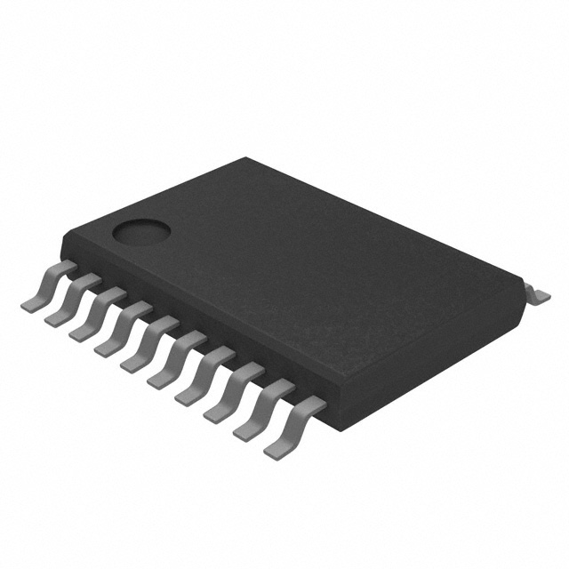


 工商网监
湘ICP备2023018690号
工商网监
湘ICP备2023018690号
