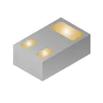
CSD17382F4
SLPS562C – APRIL 2016 – REVISED FEBRUARY 2022
CSD17382F4 30-V N-Channel FemtoFET™ MOSFET
Product Summary
1 Features
•
•
•
•
•
•
•
•
TA = 25°C
Low on-resistance
Low Qg and Qgd
Low threshold voltage
Ultra-small footprint (0402 case size)
– 1.0 mm × 0.6 mm
Ultra-low profile
– 0.36-mm height
Integrated ESD protection diode
– Rated > 3-kV HBM
– Rated > 2-kV CDM
Lead and halogen free
RoHS compliant
2 Applications
•
•
•
•
Optimized for load switch applications
Optimized for general purpose switching
applications
Single-cell battery applications
Handheld and mobile applications
3 Description
FemtoFET™
This 30-V, 54-mΩ, N-Channel
MOSFET
technology is designed and optimized to minimize the
footprint in many handheld and mobile applications.
This technology is capable of replacing standard
small signal MOSFETs while providing at least a 60%
reduction in footprint size.
.
0.36 mm
UNIT
VDS
Drain-to-Source Voltage
30
V
Qg
Gate Charge Total (4.5 V)
2.1
nC
Qgd
Gate Charge Gate-to-Drain
RDS(on)
VGS(th)
0.63
Drain-to-Source On-Resistance
nC
VGS = 1.8 V
110
mΩ
VGS = 2.5 V
67
mΩ
VGS = 4.5 V
56
mΩ
VGS = 8.0 V
54
mΩ
Threshold Voltage
0.9
V
.
Device Information
DEVICE(1)
QTY
MEDIA
PACKAGE
SHIP
CSD17382F4
3000
CSD17382F4T
250
7-Inch
Reel
Femto (0402) 1.0-mm ×
0.6-mm SMD Lead Less
Tape and
Reel
(1)
For all available packages, see the orderable addendum at
the end of the data sheet.
Absolute Maximum Ratings
TA = 25°C
VALUE
UNIT
VDS
Drain-to-Source Voltage
30
V
VGS
Gate-to-Source Voltage
10
V
ID
Continuous Drain Current(1)
2.3
A
Current(2)
IDM
Pulsed Drain
PD
Power Dissipation(1)
Human Body Model (HBM)
ESD
Rating Charged Device Model (CDM)
TJ,
Tstg
Operating Junction,
Storage Temperature
EAS
Avalanche Energy, Single Pulse ID = 6.5 A,
L = 0.1 mH, RG = 25 Ω
(1)
(2)
0.60 mm
TYPICAL VALUE
14.8
A
500
mW
3000
V
2000
V
–55 to 150
°C
2.1
mJ
Typical RθJA = 245°C/W on 1-in2 (6.45-cm2), 2-oz.
(0.071-mm) thick Cu pad on a 0.06-in (1.52-mm) thick FR4
PCB.
Pulse duration ≤100 μs, duty cycle ≤1%.
1.00 mm
D
Typical Part Dimensions
.
.
.
G
S
.
Top View
An IMPORTANT NOTICE at the end of this data sheet addresses availability, warranty, changes, use in safety-critical applications,
intellectual property matters and other important disclaimers. PRODUCTION DATA.
�CSD17382F4
www.ti.com
SLPS562C – APRIL 2016 – REVISED FEBRUARY 2022
Table of Contents
1 Features............................................................................1
2 Applications..................................................................... 1
3 Description.......................................................................1
4 Revision History.............................................................. 2
5 Specifications.................................................................. 3
5.1 Electrical Characteristics.............................................3
5.2 Thermal Information....................................................3
5.3 Typical MOSFET Characteristics................................ 4
6 Device and Documentation Support..............................7
6.1 Support Resources..................................................... 7
6.2 Receiving Notification of Documentation Updates......7
6.3 Trademarks................................................................. 7
6.4 Electrostatic Discharge Caution..................................7
6.5 Glossary......................................................................7
7 Mechanical, Packaging, and Orderable Information.... 8
7.1 Mechanical Dimensions.............................................. 8
7.2 Recommended Minimum PCB Layout........................9
7.3 Recommended Stencil Pattern................................... 9
7.4 CSD17382F4 Embossed Carrier Tape Dimensions..10
4 Revision History
NOTE: Page numbers for previous revisions may differ from page numbers in the current version.
Changes from Revision B (October 2021) to Revision C (February 2022)
Page
• Changed ultra-low profile bullet from 0.35 mm to 0.36 mm in height................................................................. 1
• Updated ultra-low profile image height from 0.35 mm to 0.36 mm..................................................................... 1
• Changed ultra-low profile image height from 0.35 mm to 0.36 mm.................................................................... 8
• Added FemtoFET Surface Mount Guide note.................................................................................................... 9
Changes from Revision A (December 2016) to Revision B (October 2021)
Page
• Updated the numbering format for tables, figures, and cross-references throughout the document..................1
Changes from Revision * (April 2016) to Revision A (December 2016)
Page
• Changed the TEST CONDITIONS for gfsTransconductance From: VDS = 15 V To: VDS = 3 V in the Section
5.1 section. ........................................................................................................................................................ 3
• Added Section 6.2 in the Section 6 section. ...................................................................................................... 7
• Updated all mechanical drawings. ..................................................................................................................... 8
2
Submit Document Feedback
Copyright © 2022 Texas Instruments Incorporated
Product Folder Links: CSD17382F4
�CSD17382F4
www.ti.com
SLPS562C – APRIL 2016 – REVISED FEBRUARY 2022
5 Specifications
5.1 Electrical Characteristics
TA = 25°C (unless otherwise stated)
PARAMETER
TEST CONDITIONS
MIN
TYP
MAX
UNIT
STATIC CHARACTERISTICS
BVDSS
Drain-to-source voltage
VGS = 0 V, IDS = 250 μA
IDSS
Drain-to-source leakage current
VGS = 0 V, VDS = 24 V
IGSS
Gate-to-source leakage current
VDS = 0 V, VGS = 10 V
VGS(th)
Gate-to-source threshold voltage
VDS = VGS, IDS = 250 μA
RDS(on)
gfs
Drain-to-source on-resistance
Transconductance
30
V
1
µA
5
µA
0.9
1.2
V
VGS = 1.8 V, IDS =0.5 A
110
180
mΩ
VGS = 2.5 V, IDS =0.5 A
67
82
mΩ
VGS = 4.5 V, IDS = 0.5 A
56
67
mΩ
VGS = 8.0 V, IDS = 0.5 A
54
64
mΩ
VDS = 3 V, IDS = 0.5 A
5.9
0.7
S
DYNAMIC CHARACTERISTICS
Ciss
Input capacitance
Coss
Output capacitance
Crss
Reverse transfer capacitance
RG
Series gate resistance
220
Qg
Gate charge total (4.5 V)
2.1
Qgd
Gate charge gate-to-drain
Qgs
Gate charge gate-to-source
Qg(th)
Gate charge at Vth
Qoss
Output charge
td(on)
Turn on delay time
tr
Rise time
td(off)
Turn off delay time
tf
Fall time
VGS = 0 V, VDS = 15 V,
ƒ = 1 MHz
VDS = 15 V, IDS = 0.5 A
VDS = 15 V, VGS = 0 V
VDS = 15 V, VGS = 4.5 V,
IDS = 0.5 A, RG = 0 Ω
267
347
pF
31.0
40.3
pF
15.0
19.5
pF
2.7
nC
Ω
0.63
nC
0.41
nC
0.12
nC
1.53
nC
59
ns
111
ns
279
ns
270
ns
DIODE CHARACTERISTICS
VSD
Diode forward voltage
ISD = 0.5 A, VGS = 0 V
0.7
1.0
V
5.2 Thermal Information
TA = 25°C (unless otherwise stated)
THERMAL METRIC
RθJA
(1)
(2)
TYPICAL VALUES
UNIT
resistance(1)
85
°C/W
Junction-to-ambient thermal resistance(2)
245
°C/W
Junction-to-ambient thermal
Device mounted on FR4 material with 1-in2 (6.45-cm2), 2-oz. (0.071-mm) thick Cu.
Device mounted on FR4 material with minimum Cu mounting area.
Submit Document Feedback
Copyright © 2022 Texas Instruments Incorporated
Product Folder Links: CSD17382F4
3
�CSD17382F4
www.ti.com
SLPS562C – APRIL 2016 – REVISED FEBRUARY 2022
5.3 Typical MOSFET Characteristics
TA = 25°C (unless otherwise stated)
Figure 5-1. Transient Thermal Impedance
10
VGS = 1.8 V
VGS = 2.5 V
VGS = 4.5 V
VGS = 8.0 V
9
8
IDS - Drain-to-Source Current (A)
IDS - Drain-to-Source Current (A)
10
7
6
5
4
3
2
1
TC = 125°C
TC = 25°C
TC = -55°C
9
8
7
6
5
4
3
2
1
0
0
0
0.1
0.2
0.3 0.4 0.5 0.6 0.7 0.8
VDS - Drain-to-Source Voltage (V)
0.9
1
0
0.5
D002
Figure 5-2. Saturation Characteristics
1
1.5
2
2.5
VGS - Gate-to-Source Voltage (V)
3
D003
VDS = 5 V
Figure 5-3. Transfer Characteristics
4
Submit Document Feedback
Copyright © 2022 Texas Instruments Incorporated
Product Folder Links: CSD17382F4
�CSD17382F4
www.ti.com
SLPS562C – APRIL 2016 – REVISED FEBRUARY 2022
1000
Ciss = Cgd + Cgs
Coss = Cds + Cgd
Crss = Cgd
7
6
C - Capacitance (pF)
VGS - Gate-to-Source Voltage (V)
8
5
4
3
100
2
1
10
0
0
0.4
0.8
1.2 1.6
2
2.4 2.8
Qg - Gate Charge (nC)
ID = 0.5 A
3.2
3.6
0
4
3
D004
6
9
12
15
18
21
24
VDS - Drain-to-Source Voltage (V)
27
30
D005
Figure 5-5. Capacitance
VDS = 15 V
1.3
130
1.2
120
RDS(on) - On-State Resistance (m:)
VGS(th) - Threshold Voltage (V)
Figure 5-4. Gate Charge
1.1
1
0.9
0.8
0.7
0.6
0.5
0.4
0.3
-75
-25
0
25
50
75 100
TC - Case Temperature (°C)
125
150
100
90
80
70
60
50
0
175
1
D006
Figure 5-6. Threshold Voltage vs Temperature
2
3
4
5
6
7
8
VGS - Gate-to-Source Voltage (V)
9
10
D007
Figure 5-7. On-State Resistance vs Gate-to-Source
Voltage
1.5
10
VGS = 2.5 V
VGS = 8.0 V
ISD - Source-To-Drain Current (A)
Normalized On-State Resistance
110
40
-50
ID = 250 µA
1.4
TC = 25°C, ID = 0.5 A
TC = 125°C, ID = 0.5 A
1.3
1.2
1.1
1
0.9
TC = 25qC
TC = 125qC
1
0.1
0.01
0.001
0.8
0.7
-75
0.0001
0
-50
-25
0
25
50
75 100
TC - Case Temperature (qC)
125
150
175
D008
ID = 0.5 A
0.2
0.4
0.6
0.8
VSD - Source-To-Drain Voltage (V)
1
D009
Figure 5-9. Typical Diode Forward Voltage
Figure 5-8. Normalized On-State Resistance vs
Temperature
Submit Document Feedback
Copyright © 2022 Texas Instruments Incorporated
Product Folder Links: CSD17382F4
5
�CSD17382F4
www.ti.com
SLPS562C – APRIL 2016 – REVISED FEBRUARY 2022
100
IAV - Peak Avalanche Current (A)
IDS - Drain-To-Source Current (A)
100
10
1
0.1
100 ms
10 ms
0.01
0.1
1 ms
100 µs
10 µs
1
10
VDS - Drain-To-Source Voltage (V)
100
TC = 25q C
TC = 125q C
10
1
0.1
0.001
0.01
TAV - Time in Avalanche (ms)
D010
Single Pulse, Typ RθJA = 245°C/W (min Cu)
Figure 5-10. Maximum Safe Operating Area (SOA)
0.1
D011
Figure 5-11. Single Pulse Unclamped Inductive
Switching
IDS - Drain-to-Source Current (A)
3.5
3
2.5
2
1.5
1
0.5
0
-50
-25
0
25
50
75
100 125
TA - Ambient Temperature (°C)
150
175
D012
Typical RθJA = 245°C/W (min Cu)
Figure 5-12. Maximum Drain Current vs Temperature
6
Submit Document Feedback
Copyright © 2022 Texas Instruments Incorporated
Product Folder Links: CSD17382F4
�CSD17382F4
www.ti.com
SLPS562C – APRIL 2016 – REVISED FEBRUARY 2022
6 Device and Documentation Support
6.1 Support Resources
TI E2E™ support forums are an engineer's go-to source for fast, verified answers and design help — straight
from the experts. Search existing answers or ask your own question to get the quick design help you need.
Linked content is provided "AS IS" by the respective contributors. They do not constitute TI specifications and do
not necessarily reflect TI's views; see TI's Terms of Use.
6.2 Receiving Notification of Documentation Updates
To receive notification of documentation updates, navigate to the device product folder on ti.com. In the upper
right corner, click on Alert me to register and receive a weekly digest of any product information that has
changed. For change details, review the revision history included in any revised document.
6.3 Trademarks
FemtoFET™ is a trademark of Texas Instruments.
TI E2E™ is a trademark of Texas Instruments.
All trademarks are the property of their respective owners.
6.4 Electrostatic Discharge Caution
This integrated circuit can be damaged by ESD. Texas Instruments recommends that all integrated circuits be handled
with appropriate precautions. Failure to observe proper handling and installation procedures can cause damage.
ESD damage can range from subtle performance degradation to complete device failure. Precision integrated circuits may
be more susceptible to damage because very small parametric changes could cause the device not to meet its published
specifications.
6.5 Glossary
TI Glossary
This glossary lists and explains terms, acronyms, and definitions.
Submit Document Feedback
Copyright © 2022 Texas Instruments Incorporated
Product Folder Links: CSD17382F4
7
�CSD17382F4
www.ti.com
SLPS562C – APRIL 2016 – REVISED FEBRUARY 2022
7 Mechanical, Packaging, and Orderable Information
The following pages include mechanical, packaging, and orderable information. This information is the most
current data available for the designated devices. This data is subject to change without notice and revision of
this document. For browser-based versions of this data sheet, refer to the left-hand navigation.
7.1 Mechanical Dimensions
1.04
0.96
A
B
PIN 1 INDEX AREA
0.64
0.56
0.36 MAX
C
SEATING PLANE
0.65
0.325
0.175
2
3
0.35
0.51
0.49
1
0.015
A.
B.
C.
8
0.16
2X
0.14
C B
A
2X
0.26
0.24
0.26
0.24
0.015
C A
B
All linear dimensions are in millimeters. Any dimensions in parenthesis are for reference only. Dimensioning and tolerancing per ASME
Y14.5M.
This drawing is subject to change without notice.
This package is a Pb-free bump design. Bump finish may vary. To determine the exact finish, refer to the device datasheet or contact a
local TI representative.
Submit Document Feedback
Copyright © 2022 Texas Instruments Incorporated
Product Folder Links: CSD17382F4
�CSD17382F4
www.ti.com
SLPS562C – APRIL 2016 – REVISED FEBRUARY 2022
7.2 Recommended Minimum PCB Layout
(0.25)
2X (0.25)
PKG
0.05 MIN
ALL AROUND
2X (0.15)
1
3
SYMM
(0.35)
(0.5)
EXAMPLE STENCIL DESIGN
2
YJC0003A(R0.05) TYP
TM
PicoStar
- 0.35 mm max height
SOLDER MASK
OPENING
(0.65)
LAND PATTERN EXAMPLE
A.
B.
PicoStar TM
METAL UNDER
SOLDER MASK
SOLDER MASK DEFINED
SCALE:50X
All dimensions are in millimeters.
For more information, see FemtoFET Surface Mount Guide (SLRA003D).
7.3 Recommended Stencil Pattern
2X (0.25)
2X (0.2)
PKG
(0.25)
1
SYMM
(0.4)
(0.5)
3
2
2X (0.15)
(R0.05) TYP
(0.65)
2X SOLDER MASK EDGE
SOLDER PASTE EXAMPLE
A.
B.
BASED ON 0.075 - 0.1 mm THICK STENCIL
All dimensions are in millimeters.
SCALE:50X
Laser cutting apertures with trapezoidal walls and rounded corners may offer better paste release. IPC-7525 may have alternate design
4220651/B 08/2015
recommendations.
NOTES: (continued)
4. For more information, see Texas Instruments literature number SLUA271 (www.ti.com/lit/slua271).
www.ti.com
Submit Document Feedback
Copyright © 2022 Texas Instruments Incorporated
Product Folder Links: CSD17382F4
9
�CSD17382F4
www.ti.com
SLPS562C – APRIL 2016 – REVISED FEBRUARY 2022
7.4 CSD17382F4 Embossed Carrier Tape Dimensions
A.
10
Pin 1 is oriented in the top-right quadrant of the tape enclosure (quadrant 2), closest to the carrier tape sprocket holes.
Submit Document Feedback
Copyright © 2022 Texas Instruments Incorporated
Product Folder Links: CSD17382F4
�PACKAGE OPTION ADDENDUM
www.ti.com
11-Jan-2022
PACKAGING INFORMATION
Orderable Device
Status
(1)
Package Type Package Pins Package
Drawing
Qty
Eco Plan
(2)
Lead finish/
Ball material
MSL Peak Temp
Op Temp (°C)
Device Marking
(3)
(4/5)
(6)
CSD17382F4
ACTIVE
PICOSTAR
YJC
3
3000
RoHS & Green
NIAU
Level-1-260C-UNLIM
-55 to 150
HM
CSD17382F4T
ACTIVE
PICOSTAR
YJC
3
250
RoHS & Green
NIAU
Level-1-260C-UNLIM
-55 to 150
HM
(1)
The marketing status values are defined as follows:
ACTIVE: Product device recommended for new designs.
LIFEBUY: TI has announced that the device will be discontinued, and a lifetime-buy period is in effect.
NRND: Not recommended for new designs. Device is in production to support existing customers, but TI does not recommend using this part in a new design.
PREVIEW: Device has been announced but is not in production. Samples may or may not be available.
OBSOLETE: TI has discontinued the production of the device.
(2)
RoHS: TI defines "RoHS" to mean semiconductor products that are compliant with the current EU RoHS requirements for all 10 RoHS substances, including the requirement that RoHS substance
do not exceed 0.1% by weight in homogeneous materials. Where designed to be soldered at high temperatures, "RoHS" products are suitable for use in specified lead-free processes. TI may
reference these types of products as "Pb-Free".
RoHS Exempt: TI defines "RoHS Exempt" to mean products that contain lead but are compliant with EU RoHS pursuant to a specific EU RoHS exemption.
Green: TI defines "Green" to mean the content of Chlorine (Cl) and Bromine (Br) based flame retardants meet JS709B low halogen requirements of