National Semiconductor
DAC161P997EVAL User’s Guide
July 20, 2011
Rev – 0.00
RoHS Compliant
Evaluation Board User's Guide
DAC161P997 Single-Wire 16-bit DAC for 4-20mA Loops
2011 National Semiconductor Corporation
Page 1 of 11
Rev: 0.00
�National Semiconductor
DAC161P997EVAL User’s Guide
1. Kit Components
Item
Qty.
Description
DAC161P997EVAL
1
DAC161P997CISQ Device evaluation board
PuffyALP_11012010_200_0026.exe
1
SPIO4
1
2011 National Semiconductor Corporation
Application software available from:
http://portal.national.com/store/view_item/index.html?nsid=D
AC161P997EVAL
USB interface board purchased separately at:
http://portal.national.com/store/view_item/index.html?nsid=S
PIO-4
Page 2 of 11
Rev: 0.00
�National Semiconductor
DAC161P997EVAL User’s Guide
2. Software Installation
Copy the installation program to a temporary directory. Start the program and follow the instruction
on the screen: the user will be asked to agree to the terms and conditions, the options will be
presented for selecting installation directory, etc. Note the path to which the software is installed
(installation_directory).
2011 National Semiconductor Corporation
Page 3 of 11
Rev: 0.00
�National Semiconductor
DAC161P997EVAL User’s Guide
3. Kit Assembly
1. Plug in the DAC161P997EVAL board into 32 pin header of the SPIO4 board
2. Plug in the USB cable into the SPIO4 board socket
3. Plug in the USB cable to the USB port on the host PC
If this is the first time this evaluation system is connected to host PC, the operating system will
attempt to install the USB driver software for the SPIO4 board. Follow the instruction on the
screen and direct the operating system to search for appropriate drivers in the
installation_directory\Drivers\NSC_USB_v1.0.8.0
4. Connect DAC161P997 Test Board to the Loop supply (up to 40V DC )
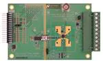
Complete evaluation system is shown below
SWIF test points
LOCAL LDO Header: shunt
is inserted by default
DAC161P997
HART input
SPIO4
ERRLVL SEL Header: shunt is
inserted in position [1,2]
(here: COM and CENTRE)
CPU Reset
5V Supply
2011 National Semiconductor Corporation
VDDIO Header: SHUNT MUST ALWAYS
BE IN POSITION [1, 2] (here: LEFT and
CENTRE)
Page 4 of 11
Rev: 0.00
�National Semiconductor
DAC161P997EVAL User’s Guide
4. Default Set-Up and Power-Up
As shipped the DAC161P997 Test Board is configured to be powered directly from the 0-20mA loop.
Local LDO (LM2936) provides 3.3V to DAC161P997 by stepping down the loop supply.
The loop is connected via terminals 5 and 6 of J1 connector. The optional shunt between terminals 2
and 3 will power up the on board diagnostic LEDs.
Jumper block
Shunt position
Function
LOCAL LDO
in
Connects the output of the 3.3V LDO to the VD (VA) rail of the
DAC161P997
ERRLVL SEL
[COM, CENTER]
Sets the input to the ERRLVL pin of DAC161P997
VDDIO
[1,2]
Provides the rail potential to the stimulus board (SPIO-4).
Once the above jumpers are in place, turn on the 5V power supply. In the configuration
shown here the loop current sourced from OUT is 3.3mA.
2011 National Semiconductor Corporation
Page 5 of 11
Rev: 0.00
�National Semiconductor
DAC161P997EVAL User’s Guide
5. ALP User Interface Software
Start by either navigating START-> National Semiconductor Corp -> Analog LaunchPAD v2…. ->Analog
LaunchPAD or, if installed, by clicking desktop shortcut.
The first screen is shown below. If the system is properly assembled the SPIO4Board 1, and PuffyDAC
should be listed in the Devices menu in the left-hand side of the window.
Click on PuffyDAC in Devices Menu to continue….
2011 National Semiconductor Corporation
Page 6 of 11
Rev: 0.00
�National Semiconductor
DAC161P997EVAL User’s Guide
“Information” Tab
Selecting PuffyDAC in the Devices menu will activate the PuffyDAC screen. This screen contains 6 tabs.
1.
2.
3.
4.
Information: Shows the basic system information
Registers: this tab is not activated in present release of software
Scripting: Python interpreter window
DAC161P997 Data: lets user send DAC output update data (DAC update data changes output
current at OUT pin of the device)
5. DAC161P997 Config: lets user send data destined for the DAC161P997 internal configuration
registers
6. Stimulus Config: lets user modify the operation of the SPIO4 board (stimulus board)
The following sections will present the tabs in order that lets the first time user produce output from
the DAC161P997 quickly.
First select “Stimulus Config” tab…..
2011 National Semiconductor Corporation
Page 7 of 11
Rev: 0.00
�National Semiconductor
DAC161P997EVAL User’s Guide
“Stimulus Config” Tab
Check the “SWIF Continuous mode”. Then go to “DAC161P997 Data” tab….
Details for later:
Control
Description of Functionality
SWIF Baud Rate
Sets the Bud rate of the SWIF link. New entry must be followed by key.
NOTE: Update stops the SWIF activity. Re-start SWIF with any of the SEND buttons in
other tabs
SWIF Continuous Mode
Set Intra-Frame Symbol=D
Set ERRLVL=HI
2011 National Semiconductor Corporation
When checked SPIO4 will continue looping through the content of the SWIF data buffer
(Continuous Mode) until STOP button is clicked
When cleared SPIO4 sends the content of the SWIF data buffer only once (One Shot
Mode )and follows it with repeated Intra-Frame symbol until STOP is clicked
NOTE: Updating this control stops SWIF if already active. Re-start SWIF with any of the
SEND buttons in other tabs
When checked SPIO4 sets the Intra-Frame Symbol to D (50% duty cycle). This setting
keeps the link active at all times, even though no meaningful data is being sent.
When cleared SPIO4 sets the Intra-Frame Symbol to LO (0% duty cycle).
NOTE: Intra-Frame Symbol exists only in the context of the “SWIF One Shot Mode”
NOTE: Updating this control stops SWIF if already active. Re-start SWIF with any of the
SEND buttons in other tabs
Instructs SPIO4 board to set HI the ERRLVL input to DAC161P997. In the default set-up
that functionality is not available. To enable it a jumper should be installed connecting
points marked with “A” on the DAC161P997 Test Board
Page 8 of 11
Rev: 0.00
�National Semiconductor
DAC161P997EVAL User’s Guide
“DAC161P997 Data” Tab
Click on and type in the “Loop Current (mA)” the desired current magnitude to be produced by
DAC161P997 output. Then press green SEND button. Observe the current….
Details for later:
Control
Description of Functionality
ACK
Check this box to insert and ACK symbol in the SWIF data stream
Send
Sends the data representing the output current magnitude to SWIF data buffer on
SPIO4, and activates the link to DAC161P997
Send File
Click this control to select a file as the source of SWIF data. SWIF data file is a text file
containing only ‘0’, ‘1’, ‘A’ or ‘D’ characters (representing valid SWIF symbols). It is up
to the user to format the data frames. When file is read-in the name of the file will
appear above “Send File” button and the “Loop Current” entry box will be cleared.
Stop
Stops SWIF activity
Check ACK, NACK
SPIO4 monitors the number of A symbols issued by the SWIF. Each symbol issued
increments the ACK count.
The number of responses from the DAC161P997 is also being monitored: for every A
issued by SWIF the lack of response from DAC161P997 increments the NACK count.
Both counters are cleared by STOP followed by SEND
2011 National Semiconductor Corporation
Page 9 of 11
Rev: 0.00
�National Semiconductor
DAC161P997EVAL User’s Guide
“DAC161P997 Config” Tab
Control
Description of Functionality
8-bit Value (bin)
Enter a string of ‘0’ and ‘1’ characters representing configuration data for each of the
DAC161P977 internal registers
ACK
same as in “DAC161P997 Data” tab
Send
Sends the register address and data to the SWIF data buffer on SPIO4, and activates the
link to DAC161P997
STOP
same as in “DAC161P997 Data” tab
Check ACK, NACK
same as in “DAC161P997 Data” tab
2011 National Semiconductor Corporation
Page 10 of 11
Rev: 0.00
�National Semiconductor
DAC161P997EVAL User’s Guide
BY USING THIS PRODUCT, YOU ARE AGREEING TO BE BOUND BY THE TERMS AND CONDITIONS OF NATIONAL
SEMICONDUCTOR'S END USER LICENSE AGREEMENT. DO NOT USE THIS PRODUCT UNTIL YOU HAVE READ AND
AGREED TO THE TERMS AND CONDITIONS OF THAT AGREEMENT. IF YOU DO NOT AGREE WITH THEM, CONTACT
THE VENDOR WITHIN TEN (10) DAYS OF RECEIPT FOR INSTRUCTIONS ON RETURN OF THE UNUSED PRODUCT FOR
A REFUND OF THE PURCHASE PRICE PAID, IF ANY.
The DAC161S055 Evaluation Board is intended for product evaluation purposes only and is not intended for resale to end
consumers, is not authorized for such use and is not designed for compliance with European EMC Directive 89/336/EEC, or for
compliance with any other electromagnetic compatibility requirements.
National Semiconductor Corporation does not assume any responsibility for use of any circuitry or software supplied or described.
No circuit patent licenses are implied.
LIFE SUPPORT POLICY
NATIONAL'S PRODUCTS ARE NOT AUTHORIZED FOR USE AS CRITICAL COMPONENTS IN LIFE SUPPORT DEVICES OR
SYSTEMS WITHOUT THE EXPRESS WRITTEN APPROVAL OF THE PRESIDENT OF NATIONAL SEMICONDUCTOR
CORPORATION. As used herein:
1. Life support devices or systems are devices or systems which, (a) are intended for surgical implant into the body, or (b)
support or sustain life, and whose failure to perform, when properly used in accordance with instructions for use provided in
the labeling, can be reasonably expected to result in a significant injury to the user.
2. A critical component is any component in a life support device or system whose failure to perform can be reasonably
expected to cause the failure of the life support device or system, or to affect its safety or effectiveness.
National Semiconductor Corporation
National Semiconductor Europe
National Semiconductor
National
Americas
Fax: +49 (0) 1 80-530 85 86
Asia Pacific Customer
Semiconductor
Tel:
1-800-272-9959
Email: europe.support@nsc.com
Response Group
Japan Ltd.
Fax:
1-800-737-7018
Deutsch Tel: +49 (0) 699508 6208
Tel: 65-2544466
Tel: 81-3-5639-7560
English Tel: +49 (0) 870 24 0 2171
Fax: 65-2504466
Fax: 81-3-5639-7507
French Tel: +49 (0) 141 91 8790
Email:sea.support@nsc.com
Email: support@nsc.com
www.national.com
National does not assume any responsibility for any circuitry described, no circuit patent licenses are implied and National reserves the right at any
time without notice to change said circuitry and specification.
2011 National Semiconductor Corporation
Page 11 of 11
Rev: 0.00
�IMPORTANT NOTICE
Texas Instruments Incorporated and its subsidiaries (TI) reserve the right to make corrections, modifications, enhancements, improvements,
and other changes to its products and services at any time and to discontinue any product or service without notice. Customers should
obtain the latest relevant information before placing orders and should verify that such information is current and complete. All products are
sold subject to TI’s terms and conditions of sale supplied at the time of order acknowledgment.
TI warrants performance of its hardware products to the specifications applicable at the time of sale in accordance with TI’s standard
warranty. Testing and other quality control techniques are used to the extent TI deems necessary to support this warranty. Except where
mandated by government requirements, testing of all parameters of each product is not necessarily performed.
TI assumes no liability for applications assistance or customer product design. Customers are responsible for their products and
applications using TI components. To minimize the risks associated with customer products and applications, customers should provide
adequate design and operating safeguards.
TI does not warrant or represent that any license, either express or implied, is granted under any TI patent right, copyright, mask work right,
or other TI intellectual property right relating to any combination, machine, or process in which TI products or services are used. Information
published by TI regarding third-party products or services does not constitute a license from TI to use such products or services or a
warranty or endorsement thereof. Use of such information may require a license from a third party under the patents or other intellectual
property of the third party, or a license from TI under the patents or other intellectual property of TI.
Reproduction of TI information in TI data books or data sheets is permissible only if reproduction is without alteration and is accompanied
by all associated warranties, conditions, limitations, and notices. Reproduction of this information with alteration is an unfair and deceptive
business practice. TI is not responsible or liable for such altered documentation. Information of third parties may be subject to additional
restrictions.
Resale of TI products or services with statements different from or beyond the parameters stated by TI for that product or service voids all
express and any implied warranties for the associated TI product or service and is an unfair and deceptive business practice. TI is not
responsible or liable for any such statements.
TI products are not authorized for use in safety-critical applications (such as life support) where a failure of the TI product would reasonably
be expected to cause severe personal injury or death, unless officers of the parties have executed an agreement specifically governing
such use. Buyers represent that they have all necessary expertise in the safety and regulatory ramifications of their applications, and
acknowledge and agree that they are solely responsible for all legal, regulatory and safety-related requirements concerning their products
and any use of TI products in such safety-critical applications, notwithstanding any applications-related information or support that may be
provided by TI. Further, Buyers must fully indemnify TI and its representatives against any damages arising out of the use of TI products in
such safety-critical applications.
TI products are neither designed nor intended for use in military/aerospace applications or environments unless the TI products are
specifically designated by TI as military-grade or "enhanced plastic." Only products designated by TI as military-grade meet military
specifications. Buyers acknowledge and agree that any such use of TI products which TI has not designated as military-grade is solely at
the Buyer's risk, and that they are solely responsible for compliance with all legal and regulatory requirements in connection with such use.
TI products are neither designed nor intended for use in automotive applications or environments unless the specific TI products are
designated by TI as compliant with ISO/TS 16949 requirements. Buyers acknowledge and agree that, if they use any non-designated
products in automotive applications, TI will not be responsible for any failure to meet such requirements.
Following are URLs where you can obtain information on other Texas Instruments products and application solutions:
Products
Applications
Audio
www.ti.com/audio
Automotive and Transportation www.ti.com/automotive
Amplifiers
amplifier.ti.com
Communications and Telecom www.ti.com/communications
Data Converters
dataconverter.ti.com
Computers and Peripherals
www.ti.com/computers
DLP® Products
www.dlp.com
Consumer Electronics
www.ti.com/consumer-apps
DSP
dsp.ti.com
Energy and Lighting
www.ti.com/energy
Clocks and Timers
www.ti.com/clocks
Industrial
www.ti.com/industrial
Interface
interface.ti.com
Medical
www.ti.com/medical
Logic
logic.ti.com
Security
www.ti.com/security
Power Mgmt
power.ti.com
Space, Avionics and Defense
www.ti.com/space-avionics-defense
Microcontrollers
microcontroller.ti.com
Video and Imaging
www.ti.com/video
RFID
www.ti-rfid.com
OMAP Mobile Processors
www.ti.com/omap
Wireless Connectivity
www.ti.com/wirelessconnectivity
TI E2E Community Home Page
e2e.ti.com
Mailing Address: Texas Instruments, Post Office Box 655303, Dallas, Texas 75265
Copyright © 2012, Texas Instruments Incorporated
�