Order
Now
Product
Folder
Support &
Community
Tools &
Software
Technical
Documents
DAC8740H, DAC8741H
SBAS856D – JUNE 2017 – REVISED MAY 2019
DAC874xH HART® and FOUNDATION Fieldbus™ and PROFIBUS PA Modems
1 Features
2 Applications
•
•
•
•
1
•
•
•
•
•
•
•
•
HART-compliant physical layer modem
– 1200-Hz, 2200-Hz HART FSK sinusoids
– Register programmable amplitude of TX
signals (DAC8741H only)
– Integrated RX demodulator and band-pass
filter with minimal external components
FOUNDATION Fieldbus compatible H1 controller
and medium attachment unit (MAU)
– 31.25 kbit/s communication based on
Manchester-coded bus powered (MBP)
– Integrated Manchester encoder and decoder
– Compatible with PROFIBUS PA
Low quiescent current: 180 µA max at typical
industrial operating temperature range (–40°C to
+85°C)
Integrated 1.5-V reference
Flexible clocking options
– Internal oscillator
– External crystal oscillator
– External CMOS clock
Digital interface
– DAC8740H: UART
– DAC8741H: SPI
Reliability: CRC bit error checking, watchdog timer
(DAC8741H only)
Wide operating temperature: –55°C to +125°C
4-mm × 4-mm QFN package
Industrial process control and automation
PLC or DCS I/O modules
Field and sensor transmitters
3 Description
The DAC8740H and DAC8741H (DAC874xH) are
HART®, FOUNDATION Fieldbus™, and PROFIBUS
PA compatible low-power modems designed for
industrial process control and industrial-automation
applications.
In HART mode, the DAC874xH integrates all of the
required circuitry to operate as half-duplex HART
physical layer modems, in either slave or master
configurations with minimal external components for
filtering. In FOUNDATION Fieldbus mode, the
DAC874xH integrates all of the required circuitry to
operate as half-duplex FOUNDATION Fieldbus
compatible H1 controllers and MAUs.
The HART, FOUNDATION Fieldbus, or PROFIBUS
PA, data stream can be transferred from the
microcontroller through either a UART interface or an
integrated FIFO accessed by a SPI interface. The
SPI interface includes an SDO pin for daisy-chain
support, various interrupts, and other extended
features.
Device Information(1)
PART NUMBER
PACKAGE
BODY SIZE (NOM)
DAC8740H
VQFN (24)
4 mm × 4 mm
DAC8741H
VQFN (24)
4 mm × 4 mm
(1) For all available packages, see the package option addendum
at the end of the data sheet.
Simplified Schematic
IOVDD
CLK_CFG0 CLK_CFG1 CLKO
Clock
Generator
XEN
X1
X2
Precision
Oscillator
REF_EN
REF
REG_CAP AVDD
Voltage
Reference
UART_IN / CS
DUPLEX / SDI
UART_OUT / SDO
UART_RTS / SCLK
Digital Interface
UART (DAC8740H), SPI
(DAC8741H),
UART/SPI (DAC8742H)
RST
CD / IRQ
HART
Transmit
Modulator
DAC
Buffer
MOD_OUT
MUX
MOD_INF
PA/FF
Receive
Demodulator
Carrier
Detect
Bandpass
Filter
MOD_IN
IF_SEL
DGND
BPFEN
AGND
1
An IMPORTANT NOTICE at the end of this data sheet addresses availability, warranty, changes, use in safety-critical applications,
intellectual property matters and other important disclaimers. PRODUCTION DATA.
�DAC8740H, DAC8741H
SBAS856D – JUNE 2017 – REVISED MAY 2019
www.ti.com
Table of Contents
1
2
3
4
5
6
7
Features ..................................................................
Applications ...........................................................
Description .............................................................
Revision History.....................................................
Device Comparison Table.....................................
Pin Configuration and Functions .........................
Specifications.........................................................
7.1
7.2
7.3
7.4
7.5
7.6
7.7
8
1
1
1
2
3
3
7
Absolute Maximum Ratings ...................................... 7
ESD Ratings.............................................................. 7
Recommended Operating Conditions....................... 7
Thermal Information .................................................. 8
Electrical Characteristics........................................... 8
Timing Requirements .............................................. 11
Typical Characteristics ............................................ 12
Detailed Description ............................................ 16
8.1 Overview ................................................................. 16
8.2 Functional Block Diagram ....................................... 16
8.3 Feature Description................................................. 16
8.4 Device Functional Modes........................................ 19
8.5 Register Maps ......................................................... 23
9
Application and Implementation ........................ 31
9.1 Application Information............................................ 31
9.2 Typical Application ................................................. 33
10 Power Supply Recommendations ..................... 37
11 Layout................................................................... 37
11.1 Layout Guidelines ................................................. 37
11.2 Layout Example .................................................... 37
12 Device and Documentation Support ................. 39
12.1
12.2
12.3
12.4
12.5
12.6
12.7
Documentation Support .......................................
Related Links ........................................................
Receiving Notification of Documentation Updates
Community Resources..........................................
Trademarks ...........................................................
Electrostatic Discharge Caution ............................
Glossary ................................................................
39
39
39
39
39
39
39
13 Mechanical, Packaging, and Orderable
Information ........................................................... 40
4 Revision History
NOTE: Page numbers for previous revisions may differ from page numbers in the current version.
Changes from Revision C (December 2018) to Revision D
Page
•
Added recommended operating temperature range, TA, to the Recommended Operating Conditions table ........................ 7
•
Changed maximum temperature test conditions for all specifications in the Electrical Characteristics table from
+125℃ to +105℃ ................................................................................................................................................................... 8
Changes from Revision B (June 2018) to Revision C
•
Page
Deleted DAC8742H from data sheet ..................................................................................................................................... 1
Changes from Revision A (December 2017) to Revision B
•
Page
DAC8741H and DAC8742H released to production .............................................................................................................. 1
Changes from Original (June 2017) to Revision A
Page
•
First public release of the full data sheet................................................................................................................................ 1
•
DAC8740H released to production......................................................................................................................................... 1
2
Submit Documentation Feedback
Copyright © 2017–2019, Texas Instruments Incorporated
Product Folder Links: DAC8740H DAC8741H
�DAC8740H, DAC8741H
www.ti.com
SBAS856D – JUNE 2017 – REVISED MAY 2019
5 Device Comparison Table
PART NUMBER
DIGITAL INTERFACE
DAC8740H
UART
DAC8741H
SPI
6 Pin Configuration and Functions
BPF_EN
REF_EN
GND
X1
X2
GND
24
23
22
21
20
19
RGE Package: DAC8740H
24-Pin VQFN
Top View
XEN
1
18
AVDD
CLKO
2
17
MOD_INF
CLK_CFG0
3
16
MOD_IN
CLK_CFG1
4
15
REF
RST
5
14
MOD_OUT
CD
6
13
REG_CAP
11
12
IOVDD
GND
9
DUPLEX
10
8
UART_RTS
UART_OUT
7
UART_IN
Thermal pad
Not to scale
Pin Functions: DAC8740H
PIN
NO.
NAME
TYPE
DESCRIPTION
Crystal oscillator enable. Logic low on this pin enables the crystal oscillator circuit; in
this mode, an external crystal is required. Logic high on this pin disables the internal
crystal oscillator circuit; in this mode an external CMOS clock or the internal oscillator
are required. No digital input pin should be left floating.
1
XEN
Digital input
2
CLKO
Digital output
3
CLK_CFG0
Digital input
Clock configuration. This pin is used to configure the input/output clocking scheme.
No digital input pin should be left floating.
4
CLK_CFG1
Digital input
Clock configuration. This pin is used to configure the input/output clocking scheme.
No digital input pin should be left floating.
5
RST
Digital input
Reset. Logic low on this pin places the DAC874xH into power-down mode and resets
the device. Logic high returns the device to normal operation. No digital input pin
should be left floating.
Clock output. If using the internal oscillator or an external crystal, this pin can be
configured as a clock output.
HART mode.
Carrier detect. A logic high on this pin indicates a valid carrier is present.
6
CD
Digital output
FF or PA mode.
While not transmitting, a logic high on this pin indicates a valid carrier is present.
While transmitting, a logic high on this pin indicates that the jabber inhibitor has
triggered.
Copyright © 2017–2019, Texas Instruments Incorporated
Product Folder Links: DAC8740H DAC8741H
Submit Documentation Feedback
3
�DAC8740H, DAC8741H
SBAS856D – JUNE 2017 – REVISED MAY 2019
www.ti.com
Pin Functions: DAC8740H (continued)
PIN
NO.
NAME
7
UART_IN
8
UART_RTS
TYPE
DESCRIPTION
Digital input
Digital input,
Digital output
UART data input. No digital input pin should be left floating.
HART mode.
Request to send. A logic high on this pin enables the demodulator and disables the
modulator. A logic low on this pin enables the modulator and disables the
demodulator. No digital input pin should be left floating.
FF or PA mode.
This pin reports transmit FIFO threshold information as programmed by the packet
initiation code.
Digital input. Logic high enables full-duplex, or internal loop-back, test mode. No
digital input pin should be left floating.
9
DUPLEX
Digital input
10
UART_OUT
Digital output
11
IOVDD
Supply
Interface supply. Supply voltage for digital input and output circuitry. This voltage sets
the logical thresholds for the digital interface.
12
GND
Supply
Digital ground. Ground reference voltage for all digital circuitry of the device.
13
REG_CAP
Analog output
Capacitor for internal regulator.
14
MOD_OUT
Analog output
Modem output. FSK output sinusoid in HART mode or Manchester coded data stream
in FOUNDATION Fieldbus and PROFIBUS PA modes. for stability, this pin requires
parallel capacitance of 5 nF to 22 nF in HART mode, or 0 pF to 100 pF in
FOUNDATION Fieldbus and PROFIBUS PA mode.
15
REF
Analog input or
output
When the internal reference is enabled, this pin outputs the internal reference voltage.
When the internal reference is disabled, this pin is the external 2.5-V reference input.
16
MOD_IN
Analog input
HART FSK input or FOUNDATION Fieldbus and PROFIBUS PA Manchester coded
data stream input. If an external filter is used, do not connect this pin.
17
MOD_INF
Analog input
If using the internal band-pass filter, connect 680 pF to this pin in HART mode, or 120
pF in FOUNDATION Fieldbus and PROFIBUS PA modes. If using an external filter,
connect the output of that filter to this pin.
18
AVDD
Supply
Power supply
19
GND
Supply
Analog ground. Ground reference voltage for power supply input.
20
X2
Analog input
Crystal stimulus
21
X1
Analog input
Crystal ro clock input
22
GND
Supply
23
REF_EN
Digital input
Reference enable. Logic high enables the internal 1.5-V reference. No digital input pin
should be left floating.
24
BPF_EN
Digital input
Filter enable. A logic high enables the internal band-pass filter. No digital input pin
should be left floating.
Thermal pad
Supply
Thermal
pad
4
Submit Documentation Feedback
UART data output
Digital ground. Ground reference voltage for all digital circuitry of the device.
Thermal pad. Connected to GND if connected to an electrical potential.
Copyright © 2017–2019, Texas Instruments Incorporated
Product Folder Links: DAC8740H DAC8741H
�DAC8740H, DAC8741H
www.ti.com
SBAS856D – JUNE 2017 – REVISED MAY 2019
BPF_EN
REF_EN
GND
X1
X2
GND
24
23
22
21
20
19
RGE Package: DAC8741H
24-Pin VQFN
Top View
XEN
1
18
AVDD
CLKO
2
17
MOD_INF
CLK_CFG0
3
16
MOD_IN
CLK_CFG1
4
15
REF
RST
5
14
MOD_OUT
IRQ
6
13
REG_CAP
7
8
9
10
11
12
CS
SCLK
SDI
SDO
IOVDD
GND
Thermal pad
Not to scale
Pin Functions: DAC8741H
PIN
NO.
NAME
TYPE
DESCRIPTION
Crystal oscillator enable. Logic low on this pin enables the crystal oscillator circuit; in
this mode, an external crystal is required. Logic high on this pin disables the internal
crystal oscillator circuit; in this mode, an external CMOS clock or the internal oscillator
are required. No digital input pin should be left floating.
1
XEN
Digital input
2
CLKO
Digital output
3
CLK_CFG0
Digital input
Clock configuration. This pin is used to configure the input/output clocking scheme.
No digital input pin should be left floating.
4
CLK_CFG1
Digital input
Clock Configuration. This pin is used to configure the input/output clocking scheme.
No digital input pin should be left floating.
5
RST
Digital input
Reset. Logic low on this pin places the DAC874xH into power-down mode and resets
the device. Logic high returns the device to normal operation. No digital input pin
should be left floating.
6
IRQ
Digital output
Digital Interrupt. The interrupt can be configured as edge sensitive or level sensitive
with positive or negative polarity, as set by the CONTROL register. Events that trigger
an interrupt are controlled by the Modem IRQ Mask register.
7
CS
Digital input
SPI chip-select. Data bits are clocked into the serial shift register when CS is low.
When CS is high, SDO is in a high-impedance state and data on SDI are ignored. No
digital input pin should be left floating.
8
SCLK
Digital input
SPI clock. Data can be transferred at rates up to 12.5 MHz. Schmitt-Trigger logic
input. No digital input pin should be left floating.
9
SDI
Digital input
SPI data input. Data are clocked into the 24-bit input shift register on the falling edge
of the serial clock input. Schmitt-Trigger logic input. No digital input pin should be left
floating.
10
SDO
Digital output
11
IOVDD
Supply
Interface supply. Supply voltage for digital input and output circuitry. This voltage sets
the logical thresholds for the digital interface.
Digital ground. Ground reference voltage for all digital circuitry of the device.
12
GND
Supply
13
REG_CAP
Analog output
Clock output. If using the internal oscillator or an external crystal, this pin can be
configured as a clock output.
SPI data output. Data are valid on the falling edge of SCLK.
Capacitor for internal regulator
Copyright © 2017–2019, Texas Instruments Incorporated
Product Folder Links: DAC8740H DAC8741H
Submit Documentation Feedback
5
�DAC8740H, DAC8741H
SBAS856D – JUNE 2017 – REVISED MAY 2019
www.ti.com
Pin Functions: DAC8741H (continued)
PIN
NO.
NAME
TYPE
DESCRIPTION
14
MOD_OUT
Analog output
Modem output. FSK output sinusoid in HART mode or Manchester coded data stream
in FOUNDATION Fieldbus and PROFIBUS PA modes. For stability, this pin requires
parallel capacitance of 5 nF to 22 nF in HART mode, or 0 pF to 100 pF in
FOUNDATION Fieldbus and PROFIBUS PA mode.
15
REF
Analog Input or
output
When the internal reference is enabled, this pin outputs the internal reference voltage.
When the internal reference is disabled, this pin is the external 2.5-V reference input.
16
MOD_IN
Analog input
HART FSK input or FOUNDATION Fieldbus and PROFIBUS PA Manchester coded
data stream input. If an external filter is used, do not connect this pin.
17
MOD_INF
Analog input
If using the internal band-pass filter, connect 680 pF to this pin, or 120 pF in
FOUNDATION Fieldbus and PROFIBUS PA modes. If using an external filter,
connect the output of that filter to this pin.
18
AVDD
Supply
Power supply
19
GND
Supply
Analog ground. Ground reference voltage for power supply input.
20
X2
Analog input
Crystal stimulus
21
X1
Analog input
Crystal or clock input
22
GND
Supply
23
REF_EN
Digital input
Reference enable. Logic high enables the internal 1.5-V reference. No digital input pin
should be left floating.
24
BPF_EN
Digital input
Filter enable. A logic high enables the internal band-pass filter. No digital input pin
should be left floating.
Thermal pad
Supply
Thermal
pad
6
Submit Documentation Feedback
Digital ground. Ground reference voltage for all digital circuitry of the device.
Thermal pad. Connected to GND if connected to an electrical potential.
Copyright © 2017–2019, Texas Instruments Incorporated
Product Folder Links: DAC8740H DAC8741H
�DAC8740H, DAC8741H
www.ti.com
SBAS856D – JUNE 2017 – REVISED MAY 2019
7 Specifications
7.1 Absolute Maximum Ratings
over operating free-air temperature range (unless otherwise noted) (1)
MIN
MAX
AVDD to GND
−0.3
6
IOVDD to GND
−0.3
6
Analog output voltage to GND
−0.3
AVDD + 0.3
Digital output voltage to GND
−0.3
IOVDD + 0.3
Analog output pin to GND
−0.3
AVDD + 0.3
Digital output pin to GND
−0.3
IOVDD + 0.3
Input current to any pin except supply pins
−10
10
mA
Operating junction temperature, TJ
−55
125
℃
Storage temperature, Tstg
−60
150
℃
Input voltage
Output voltage
Input current
(1)
UNIT
V
V
Stresses beyond those listed under Absolute Maximum Ratings may cause permanent damage to the device. These are stress ratings
only, which do not imply functional operation of the device at these or any other conditions beyond those indicated under Recommended
Operating Conditions. Exposure to absolute-maximum-rated conditions for extended periods may affect device reliability.
7.2 ESD Ratings
VALUE
V(ESD)
(1)
(2)
Electrostatic discharge
Human body model (HBM), per
ANSI/ESDA/JEDEC JS-001, all pins (1)
±8000
Charged device model (CDM), per
JEDEC specification JESD22-C101, all
pins (2)
±1500
UNIT
V
JEDEC document JEP155 states that 500-V HBM allows safe manufacturing with a standard ESD control process.
JEDEC document JEP157 states that 250-V CDM allows safe manufacturing with a standard ESD control process.
7.3 Recommended Operating Conditions
over operating free-air temperature range (unless otherwise noted)
MIN
NOM
MAX
UNIT
POWER SUPPLY
AVDD
2.7
5.5
V
IOVDD
1.71
5.5
V
V
ANALOG INPUTS
External reference input voltage
2.375
2.5
2.625
3.6864-MHz clock
3.6469
3.6864
3.7232
1.2288-MHz clock
1.2165
1.2288
1.2411
3.96
4
4.04
MHz
105
℃
DIGITAL INPUTS
External clock source frequency
(HART mode)
External clock source frequency
(FF or PA modes)
MHz
TEMPERATURE
−40
Recommended operating temperature, TA
Copyright © 2017–2019, Texas Instruments Incorporated
Product Folder Links: DAC8740H DAC8741H
Submit Documentation Feedback
7
�DAC8740H, DAC8741H
SBAS856D – JUNE 2017 – REVISED MAY 2019
www.ti.com
7.4 Thermal Information
DAC8740H, DAC8741H
THERMAL METRIC (1)
RGE
UNIT
24 PINS
RθJA
Junction-to-ambient thermal resistance
32.1
°C/W
RθJC(top)
Junction-to-case (top) thermal resistance
31.8
°C/W
RθJB
Junction-to-board thermal resistance
9.5
°C/W
ΨJT
Junction-to-top characterization parameter
0.4
°C/W
ΨJB
Junction-to-board characterization parameter
9.6
°C/W
RθJC(bot)
Junction-to-case (bottom) thermal resistance
1.7
°C/W
(1)
For more information about traditional and new thermal metrics, see the Semiconductor and IC Package Thermal Metrics application
report.
7.5 Electrical Characteristics
all specifications over –40°C to +105°C ambient operating temperature, 2.7 V ≤ AVDD ≤ 5.5 V, 1.71 V ≤ IOVDD ≤ 5.5 V,
internal reference, internal filter (unless otherwise noted)
PARAMETER
TEST CONDITIONS
MIN
TYP
MAX
UNIT
110
150
µA
220
µA
140
µA
210
µA
180
µA
250
µA
170
µA
240
µA
POWER REQUIREMENTS
AVDD and IOVDD Supply Current (HART Mode)
External clock, –40°C to +85°C
External clock, –55°C to +105℃
Demodulator active
External clock, –40°C to +85°C, external
reference
100
External clock, –55°C to +105℃, external
reference
External clock, –40°C to +85°C
160
External clock, –55°C to +105℃
Modulator active
External clock, –40°C to +85°C, external
reference
150
External clock, –55°C to +105℃, external
reference
Crystal oscillator
External crystal, 16 pF at XTAL1 and XTAL2
40
65
µA
External crystal, 36 pF at XTAL1 and XTAL2
40
65
µA
105
180
µA
Internal oscillator
External reference
SPI interface
Additional quiescent current required when
interfacing via SPI (DAC8741H only)
5
µA
AVDD and IOVDD Supply Current (FF/PA Mode)
External clock, –40°C to +85°C
160
External clock, –55°C to +105℃
Decoder active
External clock, –40°C to +85°C, external
reference
175
External clock, –55°C to +105℃, external
reference
External clock, –40°C to +85°C
175
External clock, –55°C to +105℃
Encoder active
External clock, –40°C to +85°C, external
reference
165
External clock, –55°C to +105℃, external
reference
Crystal oscillator
SPI interface
8
Submit Documentation Feedback
220
µA
330
µA
200
µA
320
µA
250
µA
360
µA
235
µA
350
µA
External crystal, 16 pF at XTAL1 and XTAL2
40
65
µA
External crystal, 36 pF at XTAL1 and XTAL2
40
65
µA
Additional quiescent current required when
interfacing via SPI (DAC8741H)
5
µA
Copyright © 2017–2019, Texas Instruments Incorporated
Product Folder Links: DAC8740H DAC8741H
�DAC8740H, DAC8741H
www.ti.com
SBAS856D – JUNE 2017 – REVISED MAY 2019
Electrical Characteristics (continued)
all specifications over –40°C to +105°C ambient operating temperature, 2.7 V ≤ AVDD ≤ 5.5 V, 1.71 V ≤ IOVDD ≤ 5.5 V,
internal reference, internal filter (unless otherwise noted)
PARAMETER
TEST CONDITIONS
MIN
TYP
MAX
UNIT
30
60
µA
182
µA
AVDD and IOVDD Supply Current (All Modes)
Power-down mode
Internal reference disabled, –40°C to +85°C,
no active clock input
Internal reference disabled, –55°C to +105℃,
no active clock input
CLOCK REQUIREMENTS
EXTERNAL CLOCK (HART MODE)
External clock source frequency
3.6864-MHz clock
3.6469
3.6864
3.7232
MHz
1.2288-MHz clock
1.2165
1.2288
1.2411
MHz
3.96
4
4.04
MHz
1.2165
1.2288
1.2411
MHz
1.47
1.5
1.53
EXTERNAL CLOCK (FF/PA MODE)
External clock source frequency
4-MHz clock
INTERNAL OSCILLATOR
Frequency
–40°C to +105℃
VOLTAGE REFERENCE
INTERNAL REFERENCE VOLTAGE
Internal reference voltage
Load regulation
Capacitive load
1.3
Specified by design
V
V/mA
1
µF
OPTIONAL EXTERNAL REFERENCE VOLTAGE
External reference input voltage
External reference input current
2.375
2.5
2.625
V
Demodulator
4.5
µA
Modulator
4.5
µA
Internal oscillator
4.5
µA
Power-down
4.5
µA
HART MODEM
MOD_IN INPUT (HART MODE)
Input voltage range
Receiver sensitivity
External reference source, specified by
design. Signal applied at the input to the dc
blocking capacitor.
0
1.5
VPP
Internal reference source, specified by
design. Signal applied at the input to the dc
blocking capacitor.
0
1.5
VPP
Threshold for successful carrier detection and
demodulation, assuming ideal sinusoidal
input FSK signals with valid preamble using
internal filter.
80
100
120
mVPP
450
460
480
mVPP
MOD_OUT OUTPUT (HART MODE)
Output voltage
AC-coupled (2.2 µF), measured at
MOD_OUT pin with 160-Ω load
Mark frequency
Internal oscillator
1200
Space frequency
Internal oscillator
2200
Frequency error
Internal oscillator, –40°C to +105℃
Phase continuity error
Specified by design
Minimum resistive load
160-Ω, ac coupled with 2.2 µF, specified by
design
Transmit impedance
RTS low, measured at the MOD_OUT pin, 1mA measurement current
RTS high, measured at the MOD_OUT pin,
±200-nA measurement current
Copyright © 2017–2019, Texas Instruments Incorporated
Product Folder Links: DAC8740H DAC8741H
-1
Hz
Hz
1
%
0
Degrees
160
Ω
13
Ω
250
kΩ
Submit Documentation Feedback
9
�DAC8740H, DAC8741H
SBAS856D – JUNE 2017 – REVISED MAY 2019
www.ti.com
Electrical Characteristics (continued)
all specifications over –40°C to +105°C ambient operating temperature, 2.7 V ≤ AVDD ≤ 5.5 V, 1.71 V ≤ IOVDD ≤ 5.5 V,
internal reference, internal filter (unless otherwise noted)
PARAMETER
TEST CONDITIONS
MIN
TYP
MAX
UNIT
FF / PA MODEM
MOD_IN INPUT (FF/PA MODE)
Input voltage range
External reference source, specified by
design. Signal applied at the input to the DC
blocking capacitor.
0
1
Vp-p
Internal reference enabled, specified by
design. Signal applied at the input to the DC
blocking capacitor.
0
1
Vp-p
-3.2
3.2
Receiver jitter tolerance
Edge-to-edge measurement of Manchester
encoded waveforms
Receiver sensitivity
Threshold for successful carrier detection and
decoding, assuming ideal Manchester
encoded input trapezoidal signals with 6µs
rise time, valid preamble byte(s) and start
delimiter byte, using internal filter.
75
µs
mVp-p
MOD_OUT OUTPUT (FF/PA MODE)
Output voltage
Maximum amplitude difference
800
Maximum difference in positive and negative
amplitude signals
Transmit bit rate
-50
31.1875
mVp-p
50
31.25
31.3125
mV
kbit/s
Transmit jitter
Measured with respect to ideal crossing of
high time and low time
-0.8
0.8
µs
Output signal distortion
Measured peak to trough distortion for
positive and negative amplitude voltage
outputs
-10
10
%
Rise and fall time
10% to 90% of peak to peak signal
8
µs
Slew rate
10% to 90% of peak to peak signal
0.2
V/µs
DIGITAL REQUIREMENTS
DIGITAL INPUTS
0.7 x
IOVDD
VIH, input high voltage
V
0.3 x
IOVDD
VIL, input low voltage
CLK_CFG0, input high voltage
Specified by design
0.8 x
IOVDD
CLK_CFG0, input mid-scale voltage
Specified by design
0.4 x
IOVDD
CLK_CFG0, input low voltage
Specified by design
V
V
0.55 x
IOVDD
V
0.15 x
IOVDD
Input current
-1
Input capcitance
1
5
µA
pF
DIGITAL OUTPUTS
VOH, output high voltage
200-µA source or sink
VOL, output low voltage
200-µA source or sink
10
Submit Documentation Feedback
IOVDD 0.5
V
0.4
V
Copyright © 2017–2019, Texas Instruments Incorporated
Product Folder Links: DAC8740H DAC8741H
�DAC8740H, DAC8741H
www.ti.com
SBAS856D – JUNE 2017 – REVISED MAY 2019
7.6 Timing Requirements
all timing conditions specified by design (unless otherwise noted)
MIN
NOM
MAX
SPI TIMING SPI TIMING SPI TIMING
UNIT
SPI TIMING
SPI TIMING
tc
SCLK cycle time
80
ns
tw1
SCLK high time
32
ns
tw2
SCLK low time
32
ns
tsu
CS to SCLK falling edge setup time
32
ns
tsu1
Data setup time
5
ns
th1
Data hold time
5
ns
td1
SCLK falling edge to CS rising edge
tw3
Minimum CS high time
tv
SCLK rising edge to SDO valid
trst
Reset low time
(1)
SPI TIMING
32
ns
3.06
us
32
ns
100
ns
HART MODE TIMING
tcstart
Carrier start time. Time from RTS falling edge to
transmit carrier reaching its first peak.
5
Bit-Times
tcstop
Carrier stop time. Time from RTS rising edge to
transmit carrier amplitude falling below the receive
amplitude.
3
Bit-Times
tcdecay
Carrier decay time. Time from RTS riding edge to
carrier amplitude dropping to zero.
6
Bit-Times
tcdeton
Carrier detect on. Time from valid carrier on receive
path to CD rising edge.
6
Bit-Times
tcdetoff1
Carrier detect off. Time from valid carrier removed on
receive path to CD falling edge.
3
ms
tcdetoff2
Carrier detect on when transitioning from transmit
mode to receive mode in the presence of a constant
valid receive carrier.
2.1
ms
tcos1
Crystal oscillator power-up time from enabling the
oscillator via clock configuration pins with 16-pF load
capacitors.
25
ms
tcos2
Crystal oscillator power-up time from enabling the
oscillator via clock configuration pins with 36-pF load
capacitors.
25
ms
tref
Reference power-up time from enabling via hardware
pin.
10
ms
tpow
Transition time from power-down mode to normal
operating mode with external clock and external
reference.
30
µs
(1)
Time between two consecutive CS rising edges must be ≥3.06 µs.
tc
1
2
24
tw1
tsu
tsu1
td1
tw2
th1
tw3
MSB
LSB
tw
MSB
LSB
trst
Figure 1. SPI Timing Diagram
Copyright © 2017–2019, Texas Instruments Incorporated
Product Folder Links: DAC8740H DAC8741H
Submit Documentation Feedback
11
�DAC8740H, DAC8741H
SBAS856D – JUNE 2017 – REVISED MAY 2019
www.ti.com
0
0
-5
-5
-10
-10
-15
Magnitude (dB)
Magnitude (dB)
7.7 Typical Characteristics
-20
-25
-30
-35
-20
-25
-30
-40
-35
-45
-40
-50
10
100
1k
10k
Frequency (Hz)
100k
-45
10
1M
1k
10k
Frequency (Hz)
100k
1M
D003
Figure 3. HART Mode Internal Band-Pass Filter Response
0
0
-5
-10
-15
-15
Magnitude (dB)
-5
-10
-20
-25
-30
-20
-25
-30
-35
-35
-40
-40
-45
10
100
D002
Figure 2. HART Mode External Band-Pass Filter Response
Magnitude (dB)
-15
100
1k
10k
Frequency (Hz)
100k
-45
10
1M
100
1k
10k
Frequency (Hz)
D004
100k
1M
D005
Figure 4. FF / PA Mode External Band-Pass Filter Response
Figure 5. FF / PA Mode Internal Band-Pass Filter Response
1.505
1.53
1.52
1.504
VREF (V)
VREF(V)
1.51
1.503
1.502
1.50
1.49
1.501
1.500
2.7
1.48
3.1
3.5
3.9
4.3
AVDD (V)
4.7
5.1
Submit Documentation Feedback
1.47
-55
-35
-15
D006
Figure 6. Internal Reference Voltage vs AVDD
12
5.5
5
25
45
65
Temperature (oC)
85
105
125
D007
Figure 7. Internal Reference Voltage vs Temperature
Copyright © 2017–2019, Texas Instruments Incorporated
Product Folder Links: DAC8740H DAC8741H
�DAC8740H, DAC8741H
www.ti.com
SBAS856D – JUNE 2017 – REVISED MAY 2019
Typical Characteristics (continued)
nRTS (2V/div)
MOD OUT (0.2V/div)
UART IN (2V/div)
nRTS (2V/div)
MOD OUT (0.2V/div)
UART IN (2V/div)
0.1 ms/ div
0.1 ms/ div
D008
Figure 8. HART TX Carrier Start Time
D009
Figure 9. HART TX Carrier Stop / Decay Time
MOD IN (0.1V/div)
CD (2V/ div)
UART OUT (2V/div)
MOD IN (0.1V/div)
CD (2V/ div)
UART OUT (2V/div)
0.5 ms/ div
1 ms/ div
D010
D011
Figure 10. HART RX Carrier Detect Off Timing
Figure 11. HART RX Carrier Detect On Timing
10
130
Modulator Active
Demodulator Active
8
7
6
5
4
3
2
110
100
90
80
70
60
1
0
1.5
Modulator Active
Demodulator Active
120
AVDD Supply Current (P$)
IOVDD Supply Current (P$)
9
2
2.5
3
3.5
4
IOVDD (V)
4.5
5
5.5
50
2.7
3
3.3
D012
Figure 12. HART Mode IOVDD Supply Current vs Voltage
With External Reference
3.6
3.9 4.2 4.5
AVDD (V)
4.8
5.1
5.4
5.7
D013
Figure 13. HART Mode AVDD Supply Current vs Voltage
With External Reference
Copyright © 2017–2019, Texas Instruments Incorporated
Product Folder Links: DAC8740H DAC8741H
Submit Documentation Feedback
13
�DAC8740H, DAC8741H
SBAS856D – JUNE 2017 – REVISED MAY 2019
www.ti.com
Typical Characteristics (continued)
10
165
Modulator Active
Demodulator Active
8
7
6
5
4
3
2
2
2.5
3
3.5
4
IOVDD (V)
4.5
5
90
75
32
152
28
148
Transmitting data
Receiving data
24
20
16
12
8
0
1.5
3.3
3.6
3.9 4.2 4.5
AVDD (V)
4.8
5.1
5.4
5.7
BPF_
D017
Transmitting data
Receiving data
144
140
136
132
128
124
2
2.5
3
3.5
4
IOVDD (V)
4.5
5
120
2.7
5.5
3.3
3.6
28
160
AVDD Supply Current (P$)
164
Transmitting data
Receiving data
20
16
12
8
4
3.9 4.2 4.5
AVDD (V)
4.8
5.1
5.4
5.7
BPF_
D015
Figure 17. FF / PA Mode AVDD Supply Current vs Voltage
With External Reference
32
24
3
D014
Figure 16. FF / PA Mode IOVDD Supply Current vs Voltage
With External Reference
0
1.5
3
Figure 15. HART Mode AVDD Supply Current vs Voltage
With Internal Reference
AVDD Supply Current (P$)
IOVDD Supply Current (P$)
105
D016
4
IOVDD Supply Current (P$)
120
45
2.7
5.5
Figure 14. HART Mode IOVDD Supply Current vs Voltage
With Internal Reference
Transmitting data
Receiving data
156
152
148
144
140
136
2
2.5
3
3.5
4
IOVDD (V)
4.5
5
5.5
Submit Documentation Feedback
132
2.7
3
3.3
D018
Figure 18. FF / PA Mode IOVDD Supply Current vs Voltage
With Internal Reference
14
135
60
1
0
1.5
Modulator Active
Demodulator Active
150
AVDD Supply Current (P$)
IOVDD Supply Current (P$)
9
3.6
3.9 4.2 4.5
AVDD (V)
4.8
5.1
5.4
5.7
BPF_
D019
Figure 19. FF / PA Mode AVDD Supply Current vs Voltage
With Internal Reference
Copyright © 2017–2019, Texas Instruments Incorporated
Product Folder Links: DAC8740H DAC8741H
�DAC8740H, DAC8741H
www.ti.com
SBAS856D – JUNE 2017 – REVISED MAY 2019
MOD OUT (0.2 V/div)
MOD OUT (0.2 V/div)
Typical Characteristics (continued)
Time (0.5 ms/div)
Time (0.5 ms/div)
D020
D021
Figure 20. Typical Manchester Encoded Trapezoid, No Filter
Figure 21. Typical Manchester Encoded Trapezoid, With
Suggested Filter Response
MOD OUT Amplitude (mVpp)
490
1.2kHz Signal
2.2kHz Signal
485
480
475
470
465
460
455
100
200
300
400
500 600
RLOAD (:)
700
800
900
1000
D025
Figure 22. MOD_OUT Voltage vs RLOAD
Copyright © 2017–2019, Texas Instruments Incorporated
Product Folder Links: DAC8740H DAC8741H
Submit Documentation Feedback
15
�DAC8740H, DAC8741H
SBAS856D – JUNE 2017 – REVISED MAY 2019
www.ti.com
8 Detailed Description
8.1 Overview
The DAC8740H and DAC8741H (DAC874xH) are HART© compliant and FOUNDATION Fieldbus or PROFIBUS
PA compatible low power modems designed for industrial process control and industrial automation applications.
In HART mode, the DAC874xH integrates all of the required circuitry to operate as half-duplex HART physical
layer modems, in either slave or master configurations with minimal external components for filtering. In
FOUNDATION Fieldbus mode, the DAC874xH integrate all of the required circuitry to operate as half-duplex
FOUNDATION Fieldbus compliant H1 Controllers and MAUs.
The HART, FOUNDATION Fieldbus, or PROFIBUS PA, data stream can be transferred from the microcontroller
through either a UART interface or an integrated FIFO accessed by a SPI interface. The SPI interface includes
an SDO pin for daisy-chain support, various interrupts, and other extended features.
8.2 Functional Block Diagram
IOVDD
CLK_CFG0 CLK_CFG1 CLKO
Clock
Generator
XEN
X1
X2
REF_EN
Precision
Oscillator
REF
REG_CAP AVDD
Voltage
Reference
CD / IRQ
UART_IN / CS
DUPLEX / SDI
UART_OUT / SDO
UART_RTS / SCLK
Digital Interface
UART (DAC8740H), SPI
(DAC8741H),
UART/SPI (DAC8742H)
RST
HART
Transmit
Modulator
DAC
Buffer
MOD_OUT
MUX
MOD_INF
PA/FF
Receive
Demodulator
Carrier
Detect
Bandpass
Filter
MOD_IN
IF_SEL
DGND
BPFEN
AGND
8.3 Feature Description
8.3.1 HART Modulator
In SPI mode, HART data is loaded into a transmit FIFO via the SPI serial interface. In UART mode, the UART
baud rate matches the HART baud rate, and therefore the FIFO is bypassed. In both cases, the input data are
translated into the mark and space frequency shift keyed (FSK) analog signals (1200 Hz and 2200 Hz,
respectively) used in HART communication using an internal HART modulator.
The HART modulator implements a look-up table containing 32 6-bit signed values that represent a single phase
continuous sinusoidal cycle. A counter is implemented that incrementally loads the table values to a digital-toanalog converter (DAC), at a clock frequency determined by the binary value of the input data, in order to create
the mark and space analog output signals used to represent HART data.
The modem operates in half-duplex mode, unless placed in full-duplex mode, where the modulator and
demodulator are not active simultaneously. The modem arbitrates over which component is active. To request
that the modulator is activated UART devices toggle the RTS pin low, SPI devices toggle the RTS bit in the
MODEM CONTROL register. These mechanics are explained in more detail in the respective sections of Device
Functional Modes.
In HART mode the MOD_OUT pin requires parallel capacitance of 5 nF to 22 nF, or 0 pF to 100 pF in
FOUNDATION Fieldbus and PROFIBUS PA mode for stability.
16
Submit Documentation Feedback
Copyright © 2017–2019, Texas Instruments Incorporated
Product Folder Links: DAC8740H DAC8741H
�DAC8740H, DAC8741H
www.ti.com
SBAS856D – JUNE 2017 – REVISED MAY 2019
Feature Description (continued)
8.3.2 HART Demodulator
The HART demodulator converts the HART FSK input signals applied at the MOD_IN or MOD_INF pins,
depending on whether an external filter is implemented, to binary data that is loaded into a receive FIFO in SPI
mode. Data in the receive FIFO can then be read by the host controller via SPI serial interface. In UART mode
received data is directly fed through to the UART interface.
When a valid carrier is detected on devices using the UART interfaces, the CD pin will toggle high. For devices
using the SPI interface, the IRQ pin toggles, indicating an alarm condition. The MODEM STATUS register can
then be read to determine the source of the interrupt, which includes a bit for carrier detection in DB1. Hysteresis
is implemented with the carrier detect feature in order to prevent erroneous carrier detection signals. More details
are explained in the respective Device Functional Modes sections.
8.3.3 FOUNDATION Fieldbus or PROFIBUS PA Manchester Encoder
FOUNDATION Fieldbus or PROFIBUS PA data is loaded into a transmit FIFO via UART or SPI interfaces which
is translated into the Manchester encoded binary analog signals used in both FOUNDATION Fieldbus and
PROFIBUS PA bus protocols through an internal Manchester encoder.
The Manchester encoder interacts with the DAC to transmit positive and negative amplitude signals, with respect
to a positive common mode voltage, to create the Manchester encoded analog outputs at 31.25 kHz baud. A
binary 0 is represented by a low-to-high transition and a binary 1 is represented by a high-to-low transition.
In both UART and SPI interfaced device, the encoder is activated any time there is data available in the transmit
FIFO and the decoder is not receiving data. In order to prevent FIFO buffer overflow, for UART mode the CD pin
acts as an interrupt to indicate when the FIFO level has exceed a programmed threshold in the packet initiation
code. In SPI mode the transmit FIFO threshold programmed in the FIFO LEVEL SET register can trigger an
interrupt on the IRQ pin. Once the IRQ interrupts is triggered, the MODEM STATUS register can then be read to
determine the source of the interrupt, which includes a bit for the FIFO level in DB4. More details are explained
in the respective Device Functional Modes sections.
8.3.4 FOUNDATION Fieldbus or PROFIBUS PA Manchester Decoder
The FOUNDATION Fieldbus and PROFIBUS PA decoder converts the Manchester encoded data applied at the
MOD_IN or MOD_INF pins, depending on whether an external filter is implemented, to binary data that is loaded
into a receive FIFO. Data in the receive FIFO can then be read by the host controller via UART or SPI serial
interfaces.
When valid data is provided to the decoder, binary data is read out serially on the UART interface. For SPI
devices, the receive FIFO is loaded until the threshold programmed in FIFO LEVEL SET is met which will trigger
an interrupt on the IRQ pin. The MODEM STATUS register can then be read to determine the source of the
interrupt, which includes a bit for the FIFO level in DB7, indicating that data is ready to be read on the SPI bus.
More details are explained in the respective Device Functional Modes sections.
8.3.5 Internal Reference
An internal reference is included in the DAC874xH. The REF_EN pin is used to enable or disable the internal
reference, when the internal reference is disabled an external reference must be provided at the REF pin. In SPI
mode, the PDVREF bit in the CONTROL register can be used to enable or disable the internal reference via
software. If the REF_EN pin is set high, the register contents of the PDVREF bit is ignored. Table 1 summarizes
how to configure the reference in either UART or SPI modes.
Table 1. Reference Configuration
INTERFACE
PDVREF
REF_EN
REFERENCE MODE
UART
1 (default)
0
External reference
UART
1 (default)
1
Internal reference
SPI
1 (default)
1
Internal reference
SPI
0
1
Internal reference
SPI
1 (default)
0
External reference
SPI
0
0
External reference
Copyright © 2017–2019, Texas Instruments Incorporated
Product Folder Links: DAC8740H DAC8741H
Submit Documentation Feedback
17
�DAC8740H, DAC8741H
SBAS856D – JUNE 2017 – REVISED MAY 2019
www.ti.com
8.3.6 Clock Configuration
All of the devices in the DAC874xH family support a variety of clocking options in order to provide system
flexibility and reduce overall current consumption in HART applications. The clocking options include: an internal
oscillator (HART mode only), an external crystal oscillator, or an external CMOS clock. The selection of the
clocking scheme is controlled by the XEN, CLK_CFG1, and CLK_CFG0 pins as described in Table 2.
The internal oscillator takes approximately 50 ms to start oscillating from when it is enabled. During this time
period the device is unable to perform modulation or demodulation activities.
Table 2. Clock Configuration Table
XEN
CLK_CFG1
CLK_CFG0
CLKO
DESCRIPTION
1
0
0
No output
3.6864-MHz CMOS clock connected at XTAL1
1
0
1
No output
1.2288-MHz CMOS clock connected at XTAL1
1
1
0
No output
Internal oscillator enabled
1
1
1
1.2288-MHz output
Internal oscillator enabled, CLKO enabled
0
0
0
No output
Crystal oscillator enabled
0
0
1
3.6864-MHz output
3.6864-MHz crystal oscillator, CLKO enabled
0
1
0
1.8432-MHz output
3.6864-MHz crystal oscillator, CLKO enabled
0
1
1
1.2288-MHz output
3.6864-MHz crystal oscillator, CLKO enabled
1
0
0.5
No output
4-MHz CMOS clock connected at XTAL1
1
1
0.5
No output
2-MHz CMOS clock connected at XTAL1
0
0
0.5
No output
4-MHz crystal oscillator
0
1
0.5
4-MHz output
4-MHz crystal oscillator, CLKO enabled
MODE
HART
FOUNDATION
Fieldbus and
PROFIBUS PA
8.3.7 Reset and Power-Down
The RST pin functions as both a hardware reset and a power-down. When the pin is brought low a reset is
issued, restoring all device components to their default state. While the pin is kept low, the device is in a powerdown state where the internal reference is disabled, the modulator and demodulator or encoder and decoder are
disabled, serial data output lines are high-impedance, MOD_OUT impedance is set to 70 kΩ, and the clock
output is disabled. If an external crystal oscillator is used, the crystal oscillator circuit remains active to reduce
start-up time when exiting the power-down state. Clock configuration pins remain active in power-down allowing
the crystal oscillator to be disabled if desired.
8.3.8 Full-Duplex Mode
In full-duplex mode the modulator and demodulator (HART mode) or encoder and decoder (FOUNDATION
Fieldbus or PROFIBUS PA mode) are simultaneously enabled. This allows a self-test feature to verify
functionality of the transmit and receive signal chains to improve system diagnostics.
8.3.9 I/O Selection
The DAC8740H implements a UART interface and the DAC8741H implements an SPI interface. The interface
mode is selected by the IF_SEL pin: a logic high on this pin sets the device to SPI mode and a logic low sets the
device to UART mode. An internal pull-down resistor is included to make sure the device powers up in a known
state, by default the pull-down sets the interface to UART mode. If changing I/O modes after power-up, a reset
command should be issued on RST.
8.3.10 Jabber Inhibitor
The DAC874xH implements a Jabber Inhibitor feature in FOUNDATION Fieldbus or PROFIBUS PA modes that
prevents the encoder from continuously transmitting data on the bus for longer than a programmed threshold
controlled by the UART or SPI interface. In SPI mode, this threshold is programmed by the PAFF_JABBER
register. In UART mode, this threshold is programmed by the four-byte initialization sequence before each
transmission. This information is described in further detail in the Device Functional Modes and Register Maps
sections.
18
Submit Documentation Feedback
Copyright © 2017–2019, Texas Instruments Incorporated
Product Folder Links: DAC8740H DAC8741H
�DAC8740H, DAC8741H
www.ti.com
SBAS856D – JUNE 2017 – REVISED MAY 2019
8.4 Device Functional Modes
8.4.1 UART Interfaced HART
When interfacing the HART modem via the UART interface, the device can be thought of as a simple UART-toHART or HART-to-UART direct feedthrough converter. The UART data is transmitted and received at 1200 baud,
which is matched to the HART FSK input and output signals.
The HART communication protocol is a half-duplex protocol which means that either the modulator or
demodulator is active, and never simultaneously enabled. The device arbitrates over which component of the
modem is active at all times based on activity on the HART bus. Bus activity is interfaced to the host controller
through the CD and RTS pins.
By default when RTS is high the demodulator is active and the modulator is inactive. When a valid carrier is
detected and data is being received by the modem, the CD pin is toggled high and binary UART data is provided
at the output. If a request to send is issued by toggling the RTS pin low while CD is high, the demodulator
remains at priority and any data provided at the UART input is ignored. When CD is low no valid carrier is
present and when RTS is brought low the modulator is activated and UART input data is latched into the
modulator and placed onto the HART bus.
8.4.2 UART Interfaced FOUNDATION Fieldbus or PROFIBUS PA
FOUNDATION Fieldbus and PROFIBUS PA are half-duplex communication protocols where only the encoder or
decoder are active at any time and the DAC874xH arbitrates over which path is active. When interfacing the
FOUNDATION Fieldbus or PROFIBUS PA modem via the UART interface, data placed in the transmit FIFO is
automatically placed on the FF/PA bus until the FIFO is empty any time the device is not receiving data,
assuming correct data format.
When receiving data the decoder will expect a preamble byte(s) and a start delimiter byte. These bytes, as well
as the stop byte, will be stripped from the UART communication and only the first data byte will be transmitted to
start the data packet. The host controller must use a timer to detect the end of the packet. Each byte transmitted
on the UART will be at 57.6 kHz baud and byte spacing of 256 µs. If a new byte has not been started within 512
µs it can be assumed that the incoming packet has ended.
The device expects to see a four byte sequence to initiate transmission: 0xEA followed by 0x80-0x9F, where bits
4:3 of the second byte configure an interrupt threshold for the transmit FIFO level and bits 2:0 set the number of
preamble bytes to be transmitted. The third byte contains the information to configure the Jabber Inhibitor
followed by the final byte of 0xAE. To send inverted Manchester encoded data the first byte, 0xEA, is inverted to
0x15 and the first three bits of the second byte are inverted such that the range of values for the second byte are
from 0x60-0x7F. The functionality of bits 4:3 and 2:0 and the Jabber Inhibitor byte remain the same and the final
byte is inverted to 0x51. The details concerning this four byte sequence are explained in Table 3 to Table 5.
Table 3. B3 and B2 UART Initialization Byte Sequence
B3
Mode
B2
D7:D0
D7
D6
D5
D4
D3
D2
D1
Noninverted
1
1
1
0
1
0
1
0
1
0
0
D2M_LEVEL
PRE_BYTES
Inverted
0
0
0
1
0
1
0
1
0
1
1
D2M_LEVEL
PRE_BYTES
Copyright © 2017–2019, Texas Instruments Incorporated
Product Folder Links: DAC8740H DAC8741H
Submit Documentation Feedback
D0
19
�DAC8740H, DAC8741H
SBAS856D – JUNE 2017 – REVISED MAY 2019
www.ti.com
Table 4. B1 and B0 UART Initialization Byte Sequence
B1
B0
Mode
D7:D0
D7
D6
D5
D4
D3
D2
D1
D0
Noninverted
JABBER_TIMEOUT
1
0
1
0
1
1
1
0
Inverted
JABBER_TIMEOUT
0
1
0
1
0
0
0
1
Table 5. B2 Bit-Field Definitions
CONTROL BITS
D2M_LEVEL
PRE_BYTES
DESCRIPTION
0
0
Alarm on UART_RTS when transmit FIFO has less than 2 bytes loaded
0
1
Alarm on UART_RTS when transmit FIFO has less than 4 bytes loaded
1
0
Alarm on UART_RTS when transmit FIFO has less than 6 bytes loaded
1
1
Alarm on UART_RTS when transmit FIFO has less than 8 bytes loaded
Number of preamble bytes is equivalent to the straight binary decimal value in this register plus one
The JABBER_TIMEOUT bits control the timeout period for the Jabber Inhibitor. If a value of 0x0 is programmed
the Jabber Inhibitor is disabled. Otherwise, the timer will be programmed in 2.048 ms increments such that the
timeout can be calculated as shown below. If the Jabber Inhibitor triggers the CD pin will be taken high. The CD
pin will be returned to logic low when the silence period of 3 seconds has ended.
TimeOut = JABBER_TIMEOUT × 2.048 ms
(1)
The encoder begins transmitting data after the following conditions are met: a valid four-byte transmission
initiation sequence has been sent to the device, the FIFO is not empty, and the device is not receiving data.
Transmission begins by sending the preamble byte or bytes, followed by a start delimiter. Then, the encoder
begins to remove data from the FIFO, and creates at least a five-byte lag of the encoder with respect to the
UART.
During transmission of a packet, the UART must take care to make sure that the FIFO does not become empty
before the packet is complete. The encoder transmits at a baud rate of 31.25 kHz or 256 µs per byte in the FIFO,
so the UART must keep up with this rate. The four-byte sequence that initiates a transmission includes setting a
transmit FIFO threshold in bits 4:3. When the FIFO level is less than or equal to this threshold, the UART_RTS
pin is taken high; this can be leveraged to make sure the FIFO is not prematurely empty. After the FIFO is
empty, a stop delimiter is placed on the bus, and a new packet can be initiated with a new four-byte transmission
initiation sequence.
The device expects a UART baud rate of 57.6 kHz. This baud rate is faster than the 31.25-kHz baud rate
specified by FOUNDATION Fieldbus and PROFIBUS PA; therefore, FIFO overflow is possible. To prevent FIFO
overflow, the UART_RTS pin FIFO threshold alarm can be leveraged by never adding more data to the FIFO
than the FIFO can contain, based on the programmed alarm threshold.
8.4.3 SPI Interfaced HART
When interfacing the HART modem via the SPI interface, the device uses transmit and receive FIFOs that are 9bits wide and 16 locations deep to buffer all HART data.
The HART communication protocol is half-duplex protocol which means that either the modulator or demodulator
is active, and never simultaneously enabled. The device arbitrates over which component of the modem is active
at all times based on activity on the HART bus. Bus activity is interfaced to the host controller through the IRQ
pin and MODEM STATUS register.
By default the demodulator is active and the modulator is inactive. When a valid carrier is detected and data is
being received by the modem, the CD bit (bit 1) in the MODEM STATUS register is set high. If the CD bit (bit 1)
in the MODEM IRQ MASK register is set to 0, this will also cause the IRQ pin to toggle as programmed in the
status CONTROL register. The IRQ pin may be programmed to be edge sensitive or level sensitive, the polarity
of the signal is also programmable. When the IRQ pin toggles, the MODEM STATUS register should be read to
determine the source of the interrupt. Receive data can be read from the RECEIVE FIFO by issuing an SPI read
command.
20
Submit Documentation Feedback
Copyright © 2017–2019, Texas Instruments Incorporated
Product Folder Links: DAC8740H DAC8741H
�DAC8740H, DAC8741H
www.ti.com
SBAS856D – JUNE 2017 – REVISED MAY 2019
Alternatively, the CD pin can be ignored by setting the CD bit (bit 1) in the MODEM IRQ MASK register to a 1. In
this mode the IRQ pin will not toggle when the CD bit in the MODEM STATUS register is a 1. Instead, a
RECEIVE FIFO read event can be triggered by the RECEIVE FIFO level threshold. This is achieved by
programming the FIFO LEVEL SET register (bits 7:4) to the desired threshold value from 1-15, if a full FIFO
(level 16 threshold) is desired the M2D FIFO FULL alarm can be used instead. If the M2D FIFO LEVEL bit (bit 7)
in the MODEM IRQ MASK register is set to 0, the IRQ pin will toggle and the MODEM STATUS register should
be read to determine the source of the interrupt. Receive data can then be read from the RECEIVE FIFO by
issuing an SPI read command.
If data is placed in the transmit FIFO while the demodulator is active and the CD bit is high, the data remains in
the FIFO until the modulator is activated. To request that the modulator is activated and the demodulator is
deactivated the RTS bit (bit 0) in the MODEM CONTROL register should be set high. When the modulator is
activated and the demodulator is deactivated the clear to send, or CTS, bit (bit 0) in the MODEM STATUS
register is set high. If the CTS bit (bit 0) in the MODEM IRQ MASK register is set to a 0 this will cause the IRQ
pin to toggle, indicating that transmit FIFO data will begin to be placed on the bus.
The level of the transmit FIFO may be monitored in order to avoid buffer overflow. This can be done either by
watching for a buffer full or buffer threshold event. To monitor by a FIFO level threshold the FIFO LEVEL SET
register (bits 3:0) can be programmed to the desired threshold value from 1-15. If the D2M FIFO LEVEL bit (bit
4) in the MODEM IRQ MASK register is set to a 0, this will cause the IRQ pin to toggle. Similarly an alarm can be
triggered based on the D2M FIFO FULL bit in the MODEM STATUS register.
8.4.4 SPI Interfaced FOUNDATION Fieldbus or PROFIBUS PA
FOUNDATION Fieldbus and PROFIBUS PA are half-duplex communication protocols, where only the encoder or
decoder are active at any time and the DAC874xH arbitrates over which path is active. When interfacing the
FOUNDATION Fieldbus or PROFIBUS PA encoder via SPI interface, data are placed in transmit and receive
FIFOs that are each 16-bytes deep to buffer all data.
When receiving data, the decoder expects a preamble byte(s) and a start delimiter byte, followed by the data
bytes for the packet, and concluded with a stop delimiter byte. All of these bytes are placed into the RECEIVE
FIFO where bits 7:0 represent the data, and bit 8 is used as a special bit to indicate the start of a packet, with
data 0x014D, the end of a packet, with data 0x0126, or a half-bit slip, with data 0x0100. If a half-bit slip occurs,
discard the packet. A timer is not necessary to detect the end of receiving a packet in SPI mode because the
stop delimiter is included in the RECEIVE FIFO data.
In order to prevent RECEIVE FIFO overflow, alarms are available to watch a threshold of the FIFO or when the
FIFO is full. If the FIFO is full it is possible for data to be lost. This is achieved by programming the FIFO LEVEL
SET register (bits 7:4) to the desired threshold value from 1-15, if a full FIFO (level 16 threshold) is desired the
M2D FIFO FULL alarm can be used instead. If the M2D FIFO LEVEL bit (bit 7) in the MODEM IRQ MASK
register is set to 0, the IRQ pin will toggle and the MODEM STATUS register should be read to determine the
source of the interrupt. Receive data can then be read from the RECEIVE FIFO by issuing an SPI read
command.
The encoder begins to send data by sending the preamble byte(s) followed by a start delimiter when the
TRANSMIT FIFO is not empty and the device is not receiving data. The number of preamble bytes used in the
packet is controlled by the PAFF PREAMBLE bits (bits14:12) in the MODEM CONTROL REGISTER. The
polarity of the Manchester encoded data can also be programmed by the PAFF POLARITY bit (bit 15) in the
MODEM CONTROL REGISTER. After transmitting the preamble byte(s) and start delimiter, the encoder begins
taking data from the TRANSMIT FIFO.
During transmission, the SPI controller must take care to make sure that the TRANSMIT FIFO does not become
empty before the packet is complete. When the TRANSMIT FIFO is empty a stop delimiter is placed on the bus.
The level of the transmit FIFO may be monitored in order to avoid buffer overflow. This monitoring can be done
either by watching for a buffer full or buffer threshold event. To monitor by a FIFO level threshold, program the
FIFO LEVEL SET register (bits 3:0) to the desired threshold value from 1-15. If the D2M FIFO LEVEL bit (bit 4)
in the MODEM IRQ MASK register is set to a 0, the IRQ pin toggles. Similarly, an alarm can be triggered based
on the D2M FIFO FULL bit in the MODEM STATUS register.
Copyright © 2017–2019, Texas Instruments Incorporated
Product Folder Links: DAC8740H DAC8741H
Submit Documentation Feedback
21
�DAC8740H, DAC8741H
SBAS856D – JUNE 2017 – REVISED MAY 2019
www.ti.com
The Jabber Inhibitor threshold is programmed by the PAFF_JABBER register (address 0x27). The 8-bit value
programmed in this register is used to calculate the threshold using Equation 2. When the timeout triggers, the
JAB_ON bit in the STATUS register is taken high, and transmission is blocked for the 3-second timeout period.
The JAB_OFF bit goes high when the timeout period has expired. Both JAB_ON and JAB_OFF bits trigger and
IRQ event, meaning the IRQ pin is triggered for both events.
TimeOut = JABBER_TIMEOUT × 2.048 ms
(2)
8.4.5 Digital Interface
8.4.5.1 UART
The behavior of the UART interface changes based on whether the device is operating in HART mode or in
FOUNDATION Fieldbus and PROFIBUS PA mode.
In HART mode, the device expects 1 start bit, 8 data bits, 1 odd parity bit, and 1 stop bit or an 8O1 UART
character format. The transmit path of the device acts as a direct feedthrough of the UART input to the HART
FSK output, therefore the UART baud rate from the host controller must be 1200 Hz ±1% as required by the
HART standard. The receive path of the device will also operate at 1200 Hz ±1%.
In FOUNDATION Fieldbus and PROFIBUS PA mode the UART interface expects 1 start bit, 8 data bits, no parity
bit, and 1 stop bit or an 8N1 UART character format. In this mode the UART interfaces transmit and receive
FIFOs so the baud rate is not required to match the 31.25 kHz baud used by FOUNDATION Fieldbus and
PROFIBUS PA. In this mode the expected transmit and receive UART baud is 57.6 Hz ±2.5%.
8.4.5.1.1 UART Carrier Detect
The behavior of the carrier detect or CD pin changes depending on whether the device is in HART mode or
FOUNDATION Fieldbus and PROFIBUS PA mode.
In HART mode the pin operates as a carrier detect pin. When a valid carrier is detected and the modem is
receiving data the CD pin is taken high. When the CD pin is high, UART data sent to the device and the request
to send, or RTS, pin will be ignored until the carrier is no longer present.
In FOUNDATION Fieldbus and PROFIBUS PA the CD pin operates as a carrier detect pin when not in transmit
mode. When the CD pin is high, UART data sent to the device are ignored until the carrier is no longer present.
When in transmit mode the CD pin functions as an alarm indicator that the jabber inhibitor has triggered and
further UART transmission data are ignored. In general, if the CD pin is high, the host controller should not be
sending transmit data to the device.
8.4.5.2 SPI
The SPI interface can operate on SCLK speeds up to 12.5 MHz, but the frame-rate must be greater than 2442
ns in HART mode and 3000 ns in FOUNDATION Fieldbus and PROFIBUS PA mode. Frames must contain at
least 24-bits without CRC enabled and 32-bits with CRC enabled. The data within the frame are right justified,
meaning that upon the rising edge of CS the right-most, or last, 24-bits or 32-bits are evaluated as the input data
word. Two modes of SPI are supported by the interface: clock polarity 0 and clock phase 1, or clock polarity 1
and clock phase 0.
The SDO pin will output data on the rising edge of SCLK or the falling edge of CS. SDO will always provide
information from the previous frame, if the previous frame was a read then the output data will be the requested
data. If the previous write was a command or register write, that data will be repeated. This allows a method for
the user to verify what was written to the device. If CRC is enabled and write data is being repeated on SDO, the
CRC provided during the previous frame will be output – not a newly calculated CRC.
The SPI frame structure is shown in Table 6. The frame includes a read/write bit, followed by a 7-bit address,
then 16-bit write data for a write frame or don’t care bits for a read frame. If CRC is enabled, an additional 8-bits
are placed at the end of the frame containing the CRC word.
Table 6. SPI Frame Structure
22
R/W FRAME
D23
D22:16
D15:0
Write Frame
0
7-Bit Address
Write Data
Read Frame
1
7-Bit Address
X
Submit Documentation Feedback
Copyright © 2017–2019, Texas Instruments Incorporated
Product Folder Links: DAC8740H DAC8741H
�DAC8740H, DAC8741H
www.ti.com
SBAS856D – JUNE 2017 – REVISED MAY 2019
8.4.5.2.1 SPI Cyclic Redundancy Check
The SPI interface includes an optional CRC mode to enhance the reliability of the interface by blocking
erroneous commands sent to the device due to noise or other errors sources. When writing to or reading from
the device the last 8-bits in the frame contain the CRC word which is calculated based on the polynomial x8 + x2
+ x + 1. If a bad CRC word is included in a write-frame to the device, the frame will be ignored. When reading
from the device, the host controller should check the CRC word to validate the frame.
Read commands with a bad CRC value will output 0x80000000 and, in the case of a receive FIFO read, prevent
data from leaving the FIFO and subsequently being lost.
8.4.5.2.2 SPI Interrupt Request
SPI interfaced devices include an interrupt request, or IRQ, pin to communicate the occurrence of a variety of
events to the host controller. The behavior of the IRQ pin is controlled by the CONTROL register and MODEM
IRQ MASK register.
The CONTROL register allows the host controller to configure the IRQ pin as level sensitive or edge sensitive via
the IRQ LEVEL bit (bit 2). For both level sensitive and edge sensitive modes, the polarity of the IRQ pin can be
set via the IRQ POLARITY bit (bit 3) in the CONTROL register.
The MODEM IRQ MASK register allows the controller to decide which events are able to trigger the IRQ pin to
toggle. If a logic 0 is written to the respective bit, that event is allowed to toggle the IRQ pin. If a logic 1 is written
to the respective bit, the event is masked from the IRQ pin.
When an event occurs the IRQ pin signal, in the case of level-sensitive configurations, is latched and the IRQ pin
voltage stays at logic high until the status has been reset, or cleared, by reading the contents of the
MODEM_STATUS register. In the case of edge-sensitive configurations a pulse is generated any time a new
event is detected.
8.5 Register Maps
Table 7 lists the memory-mapped registers for the DAC8741H. All register offset addresses not listed in Table 7
should be considered as reserved locations and the register contents should not be modified.
Table 7. DAC8741H Registers
Offset
Acronym
Register Name
2h
CONTROL
CONTROL register
Section
Go
7h
RESET
RESET register
Go
20h
MODEM_STATUS
MODEM STATUS register
Go
21h
MODEM_IRQ_MASK
MODEM IRQ MASK register
Go
22h
MODEM_CONTROL
MODEM CONTROL register
Go
23h
FIFO_D2M
FIFO D2M register
Go
24h
FIFO_M2D
FIFO M2D register
Go
25h
FIFO_LEVEL_SET
FIFO LEVEL SET register
Go
27h
PAFF_JABBER
PAFF JABBER register
Go
Complex bit access types are encoded to fit into small table cells. Table 8 shows the codes that are used for
access types in this section.
Table 8. DAC8741H Access Type Codes
Access Type
Code
Description
R
Read
W
Write
Read Type
R
Write Type
W
Reset or Default Value
-n
Value after reset or the default
value
Copyright © 2017–2019, Texas Instruments Incorporated
Product Folder Links: DAC8740H DAC8741H
Submit Documentation Feedback
23
�DAC8740H, DAC8741H
SBAS856D – JUNE 2017 – REVISED MAY 2019
www.ti.com
8.5.1 CONTROL Register (Offset = 2h) [reset = 0x8042]
This register controls the SPI watchdog timer, internal reference, CRC mode, IRQ pin behavior, and SDO pin
behavior.
CONTROL is shown in Figure 23 and described in Table 9.
Return to Summary Table.
Figure 23. CONTROL Register
15
14
13
12
11
10
9
WDTO
WDT
RESERVED
R/W
R/W
R
8
7
6
5
4
3
2
1
0
RESERVED
PDVREF
RESERVED
CRC_EN
IRQ_POL
IRQ_LEVEL
SDO_Z
SDO_B
R
R/W
R
R/W
R/W
R/W
R/W
R/W
Table 9. CONTROL Register Field Descriptions
Bit
15-13
12
11-7
24
Field
Type
Reset
Description
WDTO
R/W
100
SPI Watchdog Timer (based on 3.6864-MHz clock)
D15
D14
D13
0
0
0
50 ms
0
0
1
100 ms
0
1
0
500 ms
0
1
1
1 second
1
0
0
2 seconds (default)
1
0
1
3 seconds
1
1
0
4 seconds
1
1
1
5 seconds
WDT
R/W
0
0 = SPI Watchdog Timer Disabled (default)
1 = SPI Watchdog Timer Enabled
Timeout Period
RESERVED
R
00000
Reserved
6
PDVREF
R/W
1
This bit is only functional if the hardware reference enabled is
enabled.
0 = Internal reference is powered down
1 = Internal reference is powered up (default)
5
RESERVED
R
0
Reserved
4
CRC_EN
R/W
0
0 = No CRC (default)
1 = CRC is enabled
3
IRQ_POL
R/W
0
0 = IRQ is active low (default)
1 = IRQ is active high
2
IRQ_LEVEL
R/W
0
0 = IRQ creates a pulse for edge sensitivity (default)
1 = IRQ asserts to a level until MODEM STATUS is read
1
SDO_Z
R/W
1
0 = SDO will be driven during writes and read requests
1 = SDO will be HiZ during writes requests (default)
0
SDO_B
R/W
0
0 = SDO will remain filled from last frame (default)
1 = SDO will clear with the beginning of each frame
Submit Documentation Feedback
Copyright © 2017–2019, Texas Instruments Incorporated
Product Folder Links: DAC8740H DAC8741H
�DAC8740H, DAC8741H
www.ti.com
SBAS856D – JUNE 2017 – REVISED MAY 2019
8.5.2 RESET Register (Offset = 7h) [reset = 0x0000]
Writing 0x0001 to this register will reset all registers to their default values and the FIFOs will be emptied.
RESET is shown in Figure 24 and described in Table 10.
Return to Summary Table.
Figure 24. RESET Register
15
14
13
12
11
10
9
3
2
1
8
RESERVED
R
7
6
5
4
0
RESERVED
RST
R
R/W
Table 10. RESET Register Field Descriptions
Bit
15-1
0
Field
Type
Reset
Description
RESERVED
R/W
000000000
000000
Reserved
RST
W
0
Writing a 1 to this bit triggers a software reset.
Copyright © 2017–2019, Texas Instruments Incorporated
Product Folder Links: DAC8740H DAC8741H
Submit Documentation Feedback
25
�DAC8740H, DAC8741H
SBAS856D – JUNE 2017 – REVISED MAY 2019
www.ti.com
8.5.3 MODEM_STATUS Register (Offset = 20h) [reset = 0x0000]
The modem status register is a read/write register. When an event occurs, the corresponding bit to indicate that
event is set to a logic 1 in this register. The status bits are sticky, meaning they are not cleared unless a 1 is
written to the corresponding bit position, except for carrier detect, or CD, which responds based on the
presences of a carrier, the FIFO level registers, which respond based on the conditions of the FIFOs, and
JAB_OFF and JAB_ON which represent the current status of the jabber inibhior. CTS will assert after RTS is set
and no carrier is present if not operating in full-duplex mode.
MODEM_STATUS is shown in Figure 25 and described in Table 11.
Return to Summary Table.
Figure 25. MODEM_STATUS Register
15
14
13
12
11
10
9
8
RST
JAB_OFF
JAB_ON
GAP
FRAME
PARITY
WDT
CRC
R/W
R/W
R/W
R/W
R/W
R/W
R/W
R/W
7
6
5
4
3
2
1
0
FIFO_M2D LEVEL
FIFO_M2D FULL
FIFO_M2D EMPTY
FIFO_D2M LEVEL
FIFO_D2M FULL
FIFO_D2M EMPTY
CD
CTS
R/W
R/W
R/W
R/W
R/W
R/W
R
R
Table 11. MODEM_STATUS Register Field Descriptions
26
Bit
Field
Type
Reset
Description
15
RST
R/W
0
A reset has occurred
14
JAB_OFF
R/W
0
This bit goes high when the jabber inhibitor timeout period has
expired
13
JAB_ON
R/W
0
This bit goes high when the jabber inhibitor has been triggered
12
GAP
R/W
0
A gap error in HART mode
11
FRAME
R/W
0
A frame error in HART mode or a 1/2-bit slip in FF/PA mode
10
PARITY
R/W
0
A Parity error in HART mode
9
WDT
R/W
0
The watchdog timer has expired
8
CRC
R/W
0
An incorrect CRC word was provided in a read or write command
7
FIFO_M2D_LEVEL
R/W
0
The receive FIFO is at the programmed level
6
FIFO_M2D_FULL
R/W
0
The receive FIFO is full
5
FIFO_M2D_EMPTY
R/W
0
The receive FIFO is empty
4
FIFO_D2M_LEVEL
R/W
0
The transmit FIFO is at the programmed level
3
FIFO_D2M_FULL
R/W
0
The transmit FIFO is full
2
FIFO_D2M_EMPTY
R/W
0
The transmit FIFO is empty
1
CD
R
0
In HART mode, a valid carrier has been detected
0
CTS
R
0
In HART mode, the modem is cleared to send data and the
modulator is active
Submit Documentation Feedback
Copyright © 2017–2019, Texas Instruments Incorporated
Product Folder Links: DAC8740H DAC8741H
�DAC8740H, DAC8741H
www.ti.com
SBAS856D – JUNE 2017 – REVISED MAY 2019
8.5.4 MODEM_IRQ_MASK Register (Offset = 21h) [reset = 0x0024]
This register controls which MODEM STATUS events are allowed to trigger an interrupt on the IRQ pin. A 0 in
the respective bit position allows the interrupt event to toggle the IRQ pin. A 1 in the respective bit position blocks
the interrupt event from toggling the IRQ pin, but the event can still be detected by reading the MODEM STATUS
register.
MODEM_IRQ_MASK is shown in Figure 26 and described in Table 12.
Return to Summary Table.
Figure 26. MODEM_IRQ_MASK Register
15
14
13
12
11
10
9
8
RESERVED
JAB_OFF
JAB_ON
GAP
FRAME
PARITY
WDT
CRC
R
R/W
R/W
R/W
R/W
R/W
R/W
R/W
7
6
5
4
3
2
1
0
FIFO_M2D LEVEL
FIFO_M2D FULL
FIFO_M2D EMPTY
FIFO_D2M LEVEL
FIFO_D2M FULL
FIFO_D2M EMPTY
CD
CTS
R/W
R/W
R/W
R/W
R/W
R/W
R/W
R/W
Table 12. MODEM_IRQ_MASK Register Field Descriptions
Bit
Field
Type
Reset
Description
15
RESERVED
R/W
0
Reserved
14
JAB_OFF
R/W
0
Writing a 1 to this bit blocks the JAB_OFF event from triggering the
IRQ pin
13
JAB_ON
R/W
0
Writing a 1 to this bit blocks the JAB_ON event from triggering the
IRQ pin
12
GAP
R/W
0
Writing a 1 to this bit blocks the GAP event from triggering the IRQ
pin
11
FRAME
R/W
0
Writing a 1 to this bit blocks the FRAME event from triggering the
IRQ pin
10
PARITY
R/W
0
Writing a 1 to this bit blocks the PARITY event from triggering the
IRQ pin
9
WDT
R/W
0
Writing a 1 to this bit blocks the WDT event from triggering the IRQ
pin
8
CRC
R/W
0
Writing a 1 to this bit blocks the CRC event from triggering the IRQ
pin
7
FIFO_M2D_LEVEL
R/W
0
Writing a 1 to this bit blocks the FIFO_M2D_LEVEL event from
triggering the IRQ pin
6
FIFO_M2D_FULL
R/W
0
Writing a 1 to this bit blocks the FIFO_M2D_FULL event from
triggering the IRQ pin
5
FIFO_M2D_EMPTY
R/W
1
Writing a 1 to this bit blocks the FIFO_M2D_EMPTY event from
triggering the IRQ pin
4
FIFO_D2M_LEVEL
R/W
0
Writing a 1 to this bit blocks the FIFO_D2M_LEVEL event from
triggering the IRQ pin
3
FIFO_D2M_FULL
R/W
0
Writing a 1 to this bit blocks the FIFO_D2M_FULL event from
triggering the IRQ pin
2
FIFO_D2M_EMPTY
R/W
1
Writing a 1 to this bit blocks the FIFO_D2M_EMPTY event from
triggering the IRQ pin
1
CD
R/W
0
Writing a 1 to this bit blocks the CD event from triggering the IRQ pin
0
CTS
R/W
0
Writing a 1 to this bit blocks the CTS event from triggering the IRQ
pin
Copyright © 2017–2019, Texas Instruments Incorporated
Product Folder Links: DAC8740H DAC8741H
Submit Documentation Feedback
27
�DAC8740H, DAC8741H
SBAS856D – JUNE 2017 – REVISED MAY 2019
www.ti.com
8.5.5 MODEM_CONTROL Register (Offset = 22h) [reset = 0x0048]
This register controls various modem features including: FF/PA Manchester data polarity, number of FF/PA
preamble bits, analog output amplitude, modem enable, duplex mode, and request to send.
MODEM_CONTROL is shown in Figure 27 and described in Table 13.
Return to Summary Table.
Figure 27. MODEM_CONTROL Register
15
14
13
12
11
10
9
8
FFPA_POL
FFPA_PREAMBLE
RESERVED
TX_AMP
R/W
R/W
R
R/W
7
6
3
2
1
0
TX_AMP
5
4
MOD_EN
DUP_EN
RESERVED
RTS
R/W
R/W
R/W
R
R/W
Table 13. MODEM_CONTROL Register Field Descriptions
28
Bit
Field
Type
Reset
Description
15
FFPA_POL
R/W
0
Sets the transmitted polarity of the Manchester encoded data
0 = Logical 1 is transmitted as a transition from high-to-low (default)
1 = Logical 1 is transmitted as a transition from low-to-high
14-12
FFPA_PREAMBLE
R/W
0
Number of preamble bytes sent is the value programmed in this
register plus 1
11-9
RESERVED
R
0
Reserved
8-4
TX_AMP
R/W
00100
Unsigned binary value that controls the amplitude (HART mode only)
of the transmitted waveform in 25-mVPP steps. Default value 00100
for 500-mVPP output amplitude. Amplitude may vary from 400 mVPP
to 800 mVPP.
3
MOD_EN
R/W
1
0 = Disables TX/RX of the modem
1 = Enables TX/RX of the modem (default)
2
DUP_EN
R/W
0
0 – TX FIFO is not connected to RX FIFO (default)
1 = Connects TX FIFO to RX FIFO
1
RESERVED
R
0
Reserved
0
RTS
R/W
0
0 = No active request to send in HART mode (default)
1 = Active request to send in HART mode
Submit Documentation Feedback
Copyright © 2017–2019, Texas Instruments Incorporated
Product Folder Links: DAC8740H DAC8741H
�DAC8740H, DAC8741H
www.ti.com
SBAS856D – JUNE 2017 – REVISED MAY 2019
8.5.6 FIFO_D2M Register (Offset = 23h) [reset = 0x0200]
This register interfaces the FIFO that transmits data from the digital interface to the modem.
FIFO_D2M is shown in Figure 28 and described in Table 14.
Return to Summary Table.
Figure 28. FIFO_D2M Register
15
14
7
11
10
9
8
FIFO_LEVEL
13
LEVEL_FLAG
FULL_FLAG
EMPTY_FLAG
PARITY_BIT
R
R
R
R
W
3
2
1
0
6
12
5
4
DATA
W
Table 14. FIFO_D2M Register Field Descriptions
Field
Type
Reset
Description
15-12
Bit
FIFO_LEVEL
R
0
Reads back the current level of the FIFO, read only
11
LEVEL_FLAG
R
0
Indicates the programmed level has been reached, read only
10
FULL_FLAG
R
0
Indicates the FIFO is full, read only
9
EMPTY_FLAG
R
1
Indicates the FIFO is empty, read only
8
PARITY_BIT
W
0
Odd parity for 8-bit data read on bus, write only
DATA
W
0
Data transmitted from the digital interface to the modem, write only
7-0
8.5.7 FIFO_M2D Register (Offset = 24h) [reset = 0x0200]
This register interfaces the FIFO that receives data from the modem to the digital interface. This register is read
only
FIFO_M2D is shown in Figure 29 and described in Table 15.
Return to Summary Table.
Figure 29. FIFO_M2D Register
15
14
7
6
11
10
9
8
FIFO_LEVEL
13
12
LEVEL_FLAG
FULL_FLAG
EMPTY_FLAG
PARITY_BIT
R
R
R
R
R
3
2
1
0
5
4
DATA
R
Table 15. FIFO_M2D Register Field Descriptions
Field
Type
Reset
Description
15-12
Bit
FIFO_LEVEL
R
0
Reads back the current level of the FIFO, read only
11
LEVEL_FLAG
R
0
Indicates the programmed level has been reached, read only
10
FULL_FLAG
R
0
Indicates the FIFO is full, read only
9
EMPTY_FLAG
R
1
Indicates the FIFO is empty, read only
8
PARITY_BIT
R
0
Odd parity for 8-bit data read on bus, read only
DATA
R
0
Data transmitted from the modem to the digital interface, read only
7-0
Copyright © 2017–2019, Texas Instruments Incorporated
Product Folder Links: DAC8740H DAC8741H
Submit Documentation Feedback
29
�DAC8740H, DAC8741H
SBAS856D – JUNE 2017 – REVISED MAY 2019
www.ti.com
8.5.8 FIFO_LEVEL_SET Register (Offset = 25h) [reset = 0x0000]
This register programs the alarm threshold for both transmit and receive FIFOs. Each bit field allows for the FIFO
alarm threshold to be programmed to integer values from 1-15.
FIFO_LEVEL_SET is shown in Figure 30 and described in Table 16.
Return to Summary Table.
Figure 30. FIFO_LEVEL_SET Register
15
14
13
12
11
10
3
2
9
8
1
0
RESERVED
R
7
6
5
4
M2D_LEVEL
D2M_LEVEL
R/W
R/W
Table 16. FIFO_LEVEL_SET Register Field Descriptions
Field
Type
Reset
Description
15-8
Bit
RESERVED
R
00000000
Reserved
7-4
M2D_LEVEL
R/W
0000
The binary value in this register sets the modulator FIFO alarm
threshold
3-0
D2M_LEVEL
R/W
0000
The binary value in this register sets the demodulator FIFO alarm
threshold
8.5.9 PAFF_JABBER Register (Offset = 27h) [reset = 0x0000]
This register controls the jabber inhibitor time-out behavior. The time-out can be calculated using the equation in
Table 17, with PAFF_JABBER in decimal format.
PAFF_JABBER is shown in Figure 31 and described in Table 17.
Return to Summary Table.
Figure 31. PAFF_JABBER Register
15
14
13
12
11
10
9
8
3
2
1
0
RESERVED
R
7
6
5
4
PAFF_JABBER
R/W
Table 17. PAFF_JABBER Register Field Descriptions
Bit
30
Field
Type
Reset
Description
15-8
RESERVED
R
00000000
Reserved
7-0
PAFF_JABBER
R/W
00000000
TimeOut = JABBER_TIMEOUT * 2.048 ms
Submit Documentation Feedback
Copyright © 2017–2019, Texas Instruments Incorporated
Product Folder Links: DAC8740H DAC8741H
�DAC8740H, DAC8741H
www.ti.com
SBAS856D – JUNE 2017 – REVISED MAY 2019
9 Application and Implementation
NOTE
Information in the following applications sections is not part of the TI component
specification, and TI does not warrant its accuracy or completeness. TI’s customers are
responsible for determining suitability of components for their purposes. Customers should
validate and test their design implementation to confirm system functionality.
9.1 Application Information
The DAC874xH family of devices integrates modem functionality for several largely used Industrial protocols:
Highway Addressable Remote Transducer (HART), FOUNDATION Fieldbus (FF), and PROFIBUS (PA). The
different modes are set via the CLK_CFGx pins of the device that allow the device to either enter HART or PAFF
mode. In HART mode, a 1200-Hz/2200-Hz HART FSK Signal is modulated and demodulated, while the PAFF
mode communicates thorugh a 31.25 Kbit/s Manchester coded/encoded signal. The small package sizes, wide
temperature range and low quiescent current make this device an excellent choice for applications in industrial
process control and automation.
9.1.1 Design Recommendations
Local power supply decoupling is recommended by placing 10-µF capacitors on the IOVDD and AVDD supply
lines, and 0.1-µF capacitors close to the DAC874XH supply pins. Ceramic capacitor types such as C0G or X7R
are recommended for its optimal performance across temperature, and very low dissipation factor. DC bias
characteristics of the capacitors should also be considered when selecting passive components, such as the
voltage rating and equivalent series resistance (ESR).
9.1.2 Selecting the Crystal or Resonator
Both communication modes, HART and PAFF, require different clocking frequencies for correct operation:
HART – 1.2288 MHz or 3.686 MHz, PAFF – 4 MHz. In addition to selecting the communication mode, the
CLK_CFGx and XEN pins also select whether an internal oscillator or external clock source is configured for
device operation. The configuration table is explained in Table 2. Accuracy over the applications temperature
range should be considered when selecting the external crystal or resonator. Furthermore, crystals with a low
drift specification over the desired application temperature range should also be selected when using the
DAC874xH devices in HART, FOUNDATION Fieldbus, and PROFIBUS PA applications as communication timing
is critical. In order to reduce quiescent current consumption, the XTAL nets should be optimized during layout to
reduce any length that may increase net capacitance. This increase in capacitance is directly proportion to
current consumption.
9.1.3 Included Functions and Filter Selection
As a highly integrated device, the DAC874xH not only includes the modulation and demodulation capabilities for
the previously described industrial protocols, but also includes an internal reference, and integrated receive
bandpass filter, with other aforementioned functions. In HART mode, an internal amplifier provides high output
drive capability, and can drive a wide range of purely capacitive loads, ranging from 5 nF to 22 nF. Load
conditions within this range maintain output stability. Two different filter configurations, external and internal, are
achievable through the BPF_EN digital input -- logic high on this pin enables the internal bandpass filter. The
external filter configuration is shown in Figure 32. The example provided displays the DAC874XH device
configured with an external reference and external bandpass filter.
Copyright © 2017–2019, Texas Instruments Incorporated
Product Folder Links: DAC8740H DAC8741H
Submit Documentation Feedback
31
�DAC8740H, DAC8741H
SBAS856D – JUNE 2017 – REVISED MAY 2019
www.ti.com
Application Information (continued)
HART_OUT
4700pF
DAC8740H
0.022µF
MOD_OUT
14
MOD_IN
MOD_INF
16
17
XEN
1
X1
21
AGND
EXT REF
IOVDD
1.00M
HART_IN
150k
300pF
X2
20
1.50M
150pF
REG_CAP
13
AGND
DGND
DGND
19
12
22
PAD
25
AGND
AGND
1µF
AGND
AGND
Figure 32. HART Mode: DAC874XH Passive Selection For External Bandpass Filter and External
Reference
The second configuration, which can reduce costs associated with PCB development and BOM component
counts, additionally aids in the optimization of board space. This optimization gives the user flexibility into
achieving industrial applications with smaller form factor sizes. The internal filter configuration, with correct
MOD_IN, MOD_INF, and MOD_OUT connections, is shown in Figure 33.
HART_OUT
4700pF
DAC8740H
0.022µF
MOD_OUT
14
MOD_IN
MOD_INF
16
17
XEN
1
X1
21
X2
20
AGND
HART_IN
2200pF
IOVDD
680pF
AGND
REF
REG_CAP
13
AGND
DGND
DGND
19
12
22
PAD
25
1µF
AGND
AGND
Figure 33. HART Mode: DAC874xH Passive Selection For Internal Filter
32
Submit Documentation Feedback
Copyright © 2017–2019, Texas Instruments Incorporated
Product Folder Links: DAC8740H DAC8741H
�DAC8740H, DAC8741H
www.ti.com
SBAS856D – JUNE 2017 – REVISED MAY 2019
9.2 Typical Application
The application schematic shown in Figure 34 is described in the following sections.
C1
IOVDD
C4
4700pF
0.022 µF
AVDD
DAC8740H
C5
0.1 µF
R1
1.00M
U2
C6
0.1 µF
18
AGND
AGND
/RST
CD
UART_IN
UART_OUT
8
UART_RTS
2
3
4
CLKO
CLK_CFG0
CLK_CFG1
U1
VIN
AGND
5
VOUT
23
24
IOVDD
C3
10 µF
2
AGND
NC
1.5V_REF
2200pF
1
IOVDD
C8
680pF
21
20
REG_CAP
AGND
AGND
DGND
DGND
REF_EN
BPF_EN
15
REF
PAD
13
C9
1µF
19
12
22
AGND
25
Vref
3
4
GND
GND
X2
16
17
TP6
5V
C2
1µF
XEN
X1
10
AGND
14
C7
MOD_IN
MOD_INF
RST
CD
UART_IN
DUPLEX
AGND
/UART_RTS
MOD_OUT
IOVDD
5
6
7
9
TP5
UART_OUT
1
AVDD
11
C10
0.1 µF
AGND
DAC8740HRGE
R2
100k
AGND
AGND
TPS7B6933QDBVRQ1
AGND
24V
5V
6
C18
0.1 µF
1
C19
4.7 µF
2
GND
AGND
AGND
SCLK
SDI
/CS
3
VREF
5
6
4
SCLK
SDI
CS
R6
14.3k
3
AGND
DGND
2
OPA333AID
C13
0.012 µF
Q1
FCX690BTA
C14
300pF
R8
60.4
AGND
2
-
R9
1.80k
DAC8830IBDR
R19
C16
0.1 µF
AGND
IOVDD
1
10.0
5V
AGND
7
AGND
AGND
R7
6
2
4
5
R5
11.3k
C15
1000pF
~
NC
TP1
U6A
TP2
+
J1
D1
1
2
1
CDSOD323-T36SC
D2
40V
ED555/2DS
~
VREF
EN
3
1
3
IN
VOUT
AGND
R10
10.0
1.00M
3
3
VDD
7
4
C17
1µF
8
Vref
4
AGND
4.096V_non_buffer
U5
AGND
2,4
2
LM4132AMF-4.1
5V
R4
49.9k
AGND
U4
600 ohm
U3A
OPA335AIDR
7
C12
0.1 µF
FB1
R3
2.4k
C11
0.1 µF
4
5V
AGND
C20
1000pF
24V
U7A
R13
200
8
C21
1µF
5
IN
5V
OUT
EN
FB
1
2
C22
0.01 µF
TP3
R14
107k
R11
180
R12
10.0
C23
10 µF
TP4
4
9
AGND
AGND
FB2
600 ohm
EP GND
AGND
R15
32.8k
TPS7A4101DGNR
Copyright © 2017, Texas Instruments Incorporated
AGND
Figure 34. 2-Wire Transmitter With DAC8740H HART Modem Design Schematic
Submit Documentation Feedback
Copyright © 2017–2019, Texas Instruments Incorporated
Product Folder Links: DAC8740H DAC8741H
33
�DAC8740H, DAC8741H
SBAS856D – JUNE 2017 – REVISED MAY 2019
www.ti.com
9.2.1 Design Requirements
The application presented in Figure 34 represents a loop-powered, 2-wire, smart 4-mA to 20-mA transmitter that
commonly resides in factory control and industrial automation sectors. In this application, the DAC8740H enables
a smart interface by providing HART communication, which is responsible for modulating two-way digital
information that encapsulate a wide variety of data, including device/sensor information, calibration data, and
system diagnostic information. This circuit has been successfully HART certification and registered with the
FieldComm Group.
9.2.2 Detailed Design Procedure
9.2.2.1 DAC8740H HART Modem
In this design, the DAC8740H internal reference and band-pass filter was chosen to optimize board area,
consequently reducing form factor and cost. X7R, 10% accurate, bypass capacitances of 1-µF and 0.1-µF values
were chosen for the reference and supplies, respectively.
The DAC8740H device interfaces with the MSP430FR5969, or other similar host controller, through a standard
UART interface. The DAC8740H digital pins connected through this interface include UART_RTS, UART_OUT
(TX), UART_IN (RX), and CD.
The remaining portion of the schematic includes other TI devices that aid in the realization of a highly accurate 4mA to 20-mA, 2-wire transmitter. This combination of circuitry is an excellent choice for remote signal
conditioning of a wide variety of sensors and transducers, including thermocouples, RTDs, thermistors, and strain
gauge bridges.
The two-wire transmitter is powered from an external DC power supply that is connected via the two BUS supply
lines. The transmitter communicates by sourcing a 4-mA to 20-mA current through the connected bus, and back
to the central host, which is typically a PLC analog input module. This expressed range of 4 mA to 20 mA is
typically employed to adhere to industry standard, and makes sure that the transmitter receives a minimum of 4
mA for correct powered operation.
Vref
MOD_OUT
R2
100k
MOD_IN
VREF/(R2+R3)
VHART/(R4)
R3
2.4k
V+
VDAC/(R5+R6) R4
R5
DAC8830
11.3k
A1
49.9k
R6
R7
10.0
14.3k
A2
C13
0.012 µ F
ILOOP
R8
60.4
R9
1.80k
1000pF
Iq
R10
10.0
C20
I1
R11
180
I2
R12
10.0
V-
Figure 35. Simplified Schematic of the 2-Wire Current Loop
34
Submit Documentation Feedback
Copyright © 2017–2019, Texas Instruments Incorporated
Product Folder Links: DAC8740H DAC8741H
�DAC8740H, DAC8741H
www.ti.com
SBAS856D – JUNE 2017 – REVISED MAY 2019
9.2.2.2 2-Wire Current Loop
The A2 op amp employs negative feedback to drive the potential at both input nodes, V+ and V–, to the same
voltage. This establishes the set of KCL equations (1) – assuming no HART communication, VHART = 0 V.
I1 = VDAC / (25.6 kΩ) + VREF / (102.4 kΩ)
(3)
A2 also drives the base of the NPN BJT, Q1, which enables current to flow from its collector through emitter pins
and through the R8 resistor, while maintaining an equivalent potential drop from its input nodes to the net
represented by TP4. This configuration drives the combined voltage drop across R9 and R11 to the same
voltage drop across R10 and R12.
Using this relationship, along with current Equation 3 and Equation 4, IOUT is calculated as follows:
I2 = I1 * (1.80 kΩ + 180) / (10 + 10) = I1 * (1.980 kΩ / 20) = I1 * 99
IOUT = I1 + I2 = [VDAC / (25.6 kΩ) + VREF / (102.4 kΩ)] + I1 * 99 = [VDAC / (25.6 kΩ) + VREF / (102.4 kΩ)] * (100)
(4)
(5)
For a VREF value of 4.096 V, the zero-scale portion of the transfer function, [VREF / (102.4 kΩ)] * (100),
translates to 4 mA, while the span, [VDAC / (25.6 kΩ)] * 100, encompasses 16 mA. This final product is a system
capable of sourcing 4 mA to 20 mA, which is dependent on DAC output voltage. The value of R4 is responsible
for converting the 500-mVPP HART signal into a 1-mA PP frequency shift keyed (FSK) signal that resides on top
of the 4-mA to 20-mA analog current signal.
9.2.2.3 Regulator
The primary supply for the transmitter is the TPS7A4101 device, which is a 50-V input, 50-mA Single output lowdropout linear regulator with very low quiescent current, 25 µA. The device supplies a well-regulated voltage rail
(1% accuracy), operating within an extended temperature range of –40°C to +125°C, and also withstands and
maintains regulation during very high and fast voltage transients. In this design the LDO converts the external
supply to a 5-V rail that is used by the DAC8830, LM4132 and OPA333/OPA335. The 200-Ω resistor that
separates the loop supply from the LDO acts as a current limiting resistor at startup and additionally improves the
overall receiver impedance of the design.
Generally, series references are preferred over shunt references because of their lower power consumption; in
this case the LM4132 exhibits a maximum of 60-µA quiescent current. Moreover, the device has an initial
accuracy of 0.05% with a specified temperature coefficient of 10 ppm/°C or less, and is capable of operating with
these metrics at an extended temperature range of –40°C to +125°C.
In order to generate a 3.3-V supply for the DAC8740H, the TPS7B6933-Q1, a low-dropout linear regulator with
low quiescent current, is incorporated into the design. This LDO is capable of operating over a wide temperature
range of –40°C to 125°C, while exhibiting a maximum quiescent value of 25 µA over this temperature range.
9.2.2.4 DAC
After sufficient bypass, this precision reference voltage is applied to the VREF pin of the DAC8830 device. An
accurate reference along with an accurate DAC are largely responsible for the overall accuracy of the current
loop, as any accuracy errors associated with the DAC will propagate through the rest of the signal chain and
decrease the accuracy of the solution. In this case, the DAC8830, a 16-bit voltage-output DAC with excellent
linearity (1 LSB INL), low glitch, low noise, and fast settling was chosen to set the base line performance of the
design.
9.2.2.5 Amplifiers
Next, the voltage output is buffered with the OPA333 CMOS operation amplifier, which features near-zero drift
over time and temperature, low quiescent current (17 µA), and single supply operation with rail-to-rail output that
swings within 50 mV of the supply rail.
As with the OPA333, the OPA335 was chosen due to its excellent DC accuracy specifications. These parameters
include low input bias current, low offset voltage, and high CMRR/PSRR. In addition to these DC specifications,
the OPA335 features an operating bandwidth of up to 2 MHz, which provides ample margin for HART
communication.
Copyright © 2017–2019, Texas Instruments Incorporated
Product Folder Links: DAC8740H DAC8741H
Submit Documentation Feedback
35
�DAC8740H, DAC8741H
SBAS856D – JUNE 2017 – REVISED MAY 2019
www.ti.com
9.2.2.6 Diodes
For transient voltage protection, a 40-V bidirectional transient voltage suppressor (TVS) diode is placed across
the BUS lines of the design. Certain criteria should be considered when making this diode selection, such as the
diode’s working voltage, breakdown voltage, leakage current and power rating. In addition to these parameters,
leakage current should also be factored into the design as it will impact the accuracy of the analog current loop.
2-wire polarity protection is also employed by using the DSRHD10 as a diode bridge rectifier. The placement of
this component makes sure that the current loop will always correctly operate regardless of the arrangement of
input connections. As with other elements, consider the leakage and biasing voltages because these voltages
affect system accuracy and compliance voltage.
9.2.2.7 Passives
Among the passives included in the design, the gain setting resistors should be chosen to exhibit tight tolerances
in order to achieve high accuracy. These resistors -- R4, R5, R6, R9, R11, R10, and R12 -- are primarily
responsible for setting the gain of the current loop, along with primary path of the output current flow. Since the
biased transistor, Q1, is responsible for sourcing most of the output current, components in the path of this
current flow should be chosen with appropriate power ratings. In this case R8 is a 0.25-W resistor.
9.2.3 Application Curves
Five hundred data points were taken on five different boards, producing the 4-mA to 20-mA transfer function
below in Figure 36. The total unadjusted error (TUE) of the transmitters is displayed in Figure 37.
Figure 36. 4-mA to 20-mA Transfer Function
Figure 37. Total Unadjusted Error Graph of Application Circuit
36
Submit Documentation Feedback
Copyright © 2017–2019, Texas Instruments Incorporated
Product Folder Links: DAC8740H DAC8741H
�DAC8740H, DAC8741H
www.ti.com
SBAS856D – JUNE 2017 – REVISED MAY 2019
10 Power Supply Recommendations
The DAC874xH can operate with analog supplies from 2.7 V to 5.5 V and digital supplies from 1.71 V to 5.5 V,
enabling interfacing host controller platforms with low voltage digital logic. For applications that are particularly
focused on reducing power dissipation in the modem, use the lowest supply voltage available for both analog
and digital supplies.
11 Layout
11.1 Layout Guidelines
Precision designs require careful layout, the list below provides some insight into good layout practices.
• Bypass all power-supply pins to ground with a low ESR ceramic bypass capacitor. The typical recommended
bypass capacitance is 0.1 to 1 µF ceramic with a X7R or NP0 dielectric.
• Place power supply and reference bypass capacitors close to the terminals to minimize inductance and
optimize performance.
• A high-quality ceramic type NP0 or X7R is recommended for its optimal performance across temperature, and
very low dissipation factor.
• The digital and analog sections should have proper placement with respect to the digital and analog
components. The separation of analog and digital circuitry allows for better design and practice as it allows
less coupling into neighboring blocks, and minimizes the interaction between analog and digital return
currents.
11.2 Layout Example
Bypass
Capacitor
12
6
1
18
24
Bypass
Capacitor
Figure 38. DAC8740H Basic Layout Example
Copyright © 2017–2019, Texas Instruments Incorporated
Product Folder Links: DAC8740H DAC8741H
Submit Documentation Feedback
37
�DAC8740H, DAC8741H
SBAS856D – JUNE 2017 – REVISED MAY 2019
www.ti.com
Layout Example (continued)
Figure 39. 2-Wire Transmitter With DAC8740H HART Modem Layout - Top Layer
Figure 40. 2-Wire Transmitter With DAC8740H HART Modem Layout - Bottom Layer
38
Submit Documentation Feedback
Copyright © 2017–2019, Texas Instruments Incorporated
Product Folder Links: DAC8740H DAC8741H
�DAC8740H, DAC8741H
www.ti.com
SBAS856D – JUNE 2017 – REVISED MAY 2019
12 Device and Documentation Support
12.1 Documentation Support
12.1.1 Related Documentation
For related documentation see the following:
Texas Instruments, DAC8742H Evaluation Module user's guide (functional for the DAC8740H and DAC8741H)
12.2 Related Links
Table 18 lists quick access links. Categories include technical documents, support and community resources,
tools and software, and quick access to sample or buy.
Table 18. Related Links
PARTS
PRODUCT FOLDER
ORDER NOW
TECHNICAL
DOCUMENTS
TOOLS &
SOFTWARE
SUPPORT &
COMMUNITY
DAC8740H
Click here
Click here
Click here
Click here
Click here
DAC8741H
Click here
Click here
Click here
Click here
Click here
12.3 Receiving Notification of Documentation Updates
To receive notification of documentation updates, navigate to the device product folder on ti.com. In the upper
right corner, click on Alert me to register and receive a weekly digest of any product information that has
changed. For change details, review the revision history included in any revised document.
12.4 Community Resources
The following links connect to TI community resources. Linked contents are provided "AS IS" by the respective
contributors. They do not constitute TI specifications and do not necessarily reflect TI's views; see TI's Terms of
Use.
TI E2E™ Online Community TI's Engineer-to-Engineer (E2E) Community. Created to foster collaboration
among engineers. At e2e.ti.com, you can ask questions, share knowledge, explore ideas and help
solve problems with fellow engineers.
Design Support TI's Design Support Quickly find helpful E2E forums along with design support tools and
contact information for technical support.
12.5 Trademarks
E2E is a trademark of Texas Instruments.
FOUNDATION Fieldbus is a trademark of FieldComm Group.
HART is a registered trademark of FieldComm Group.
All other trademarks are the property of their respective owners.
12.6 Electrostatic Discharge Caution
This integrated circuit can be damaged by ESD. Texas Instruments recommends that all integrated circuits be handled with
appropriate precautions. Failure to observe proper handling and installation procedures can cause damage.
ESD damage can range from subtle performance degradation to complete device failure. Precision integrated circuits may be more
susceptible to damage because very small parametric changes could cause the device not to meet its published specifications.
12.7 Glossary
SLYZ022 — TI Glossary.
This glossary lists and explains terms, acronyms, and definitions.
Copyright © 2017–2019, Texas Instruments Incorporated
Product Folder Links: DAC8740H DAC8741H
Submit Documentation Feedback
39
�DAC8740H, DAC8741H
SBAS856D – JUNE 2017 – REVISED MAY 2019
www.ti.com
13 Mechanical, Packaging, and Orderable Information
The following pages include mechanical, packaging, and orderable information. This information is the most
current data available for the designated devices. This data is subject to change without notice and revision of
this document. For browser-based versions of this data sheet, refer to the left-hand navigation.
40
Submit Documentation Feedback
Copyright © 2017–2019, Texas Instruments Incorporated
Product Folder Links: DAC8740H DAC8741H
�PACKAGE OPTION ADDENDUM
www.ti.com
10-Dec-2020
PACKAGING INFORMATION
Orderable Device
Status
(1)
Package Type Package Pins Package
Drawing
Qty
Eco Plan
(2)
Lead finish/
Ball material
MSL Peak Temp
Op Temp (°C)
Device Marking
(3)
(4/5)
(6)
DAC8740HRGER
ACTIVE
VQFN
RGE
24
3000
RoHS & Green
NIPDAUAG
Level-2-260C-1 YEAR
-55 to 125
DAC
8740H
DAC8740HRGET
ACTIVE
VQFN
RGE
24
250
RoHS & Green
NIPDAUAG
Level-2-260C-1 YEAR
-55 to 125
DAC
8740H
DAC8741HRGER
ACTIVE
VQFN
RGE
24
3000
RoHS & Green
NIPDAUAG
Level-2-260C-1 YEAR
-55 to 125
DAC
8741H
DAC8741HRGET
ACTIVE
VQFN
RGE
24
250
RoHS & Green
NIPDAUAG
Level-2-260C-1 YEAR
-55 to 125
DAC
8741H
(1)
The marketing status values are defined as follows:
ACTIVE: Product device recommended for new designs.
LIFEBUY: TI has announced that the device will be discontinued, and a lifetime-buy period is in effect.
NRND: Not recommended for new designs. Device is in production to support existing customers, but TI does not recommend using this part in a new design.
PREVIEW: Device has been announced but is not in production. Samples may or may not be available.
OBSOLETE: TI has discontinued the production of the device.
(2)
RoHS: TI defines "RoHS" to mean semiconductor products that are compliant with the current EU RoHS requirements for all 10 RoHS substances, including the requirement that RoHS substance
do not exceed 0.1% by weight in homogeneous materials. Where designed to be soldered at high temperatures, "RoHS" products are suitable for use in specified lead-free processes. TI may
reference these types of products as "Pb-Free".
RoHS Exempt: TI defines "RoHS Exempt" to mean products that contain lead but are compliant with EU RoHS pursuant to a specific EU RoHS exemption.
Green: TI defines "Green" to mean the content of Chlorine (Cl) and Bromine (Br) based flame retardants meet JS709B low halogen requirements of
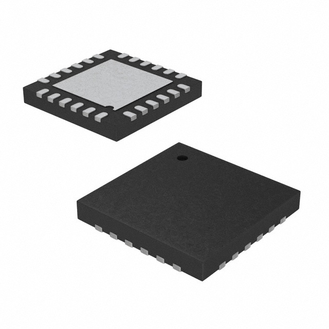


 工商网监
湘ICP备2023018690号
工商网监
湘ICP备2023018690号
