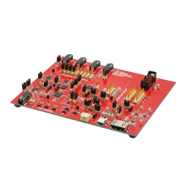
User's Guide
SLOU361 – February 2013
DANCEVM-A
The Digital ANC EVM-A (DANCEVM-A) allows on-the-fly tuning of Digital Noise-Cancelling headphones
using PurePath™ Studio.
1
2
3
4
Contents
Introduction .................................................................................................................. 2
Getting Started .............................................................................................................. 2
2.1
Hardware Setup .................................................................................................... 2
2.2
Loading Code from PurePath Studio ............................................................................ 3
DANCEVM-A Default Jumper Settings ................................................................................... 6
DANCEVM-A Schematics, Layout Views and Bill of Materials ....................................................... 7
4.1
DANCEVM-A Schematics ......................................................................................... 7
4.2
DANCEVM-A Layout Views ..................................................................................... 17
4.3
DANCEVM-A Bill of Materials ................................................................................... 18
List of Figures
1
Default DANCEVM-A Jumper Settings................................................................................... 3
2
Generic Music Chip Process Flow ........................................................................................ 4
3
PPS Device Select (Music Chip) .......................................................................................... 4
4
Generic DANC Chip Process Flow ....................................................................................... 4
5
PPS Device Select (DANC Chips) ........................................................................................ 5
6
Feedback ANC Component Properties .................................................................................. 5
7
Hybrid ANC Component Properties ...................................................................................... 5
8
DANCEVM-A Schematic - Page 1 of 10 ................................................................................. 7
9
DANCEVM-A Schematic - Page 2 of 10 ................................................................................. 8
10
DANCEVM-A Schematic - Page 3 of 10 ................................................................................. 9
11
DANCEVM-A Schematic - Page 4 of 10
10
12
DANCEVM-A Schematic - Page 5 of 10
11
13
14
15
16
17
18
...............................................................................
...............................................................................
DANCEVM-A Schematic - Page 6 of 10 ...............................................................................
DANCEVM-A Schematic - Page 7 of 10 ...............................................................................
DANCEVM-A Schematic - Page 8 of 10 ...............................................................................
DANCEVM-A Schematic - Page 9 of 10 ...............................................................................
DANCEVM-A Schematic - Page 10 of 10 ..............................................................................
DANCEVM-A Layout View ...............................................................................................
12
13
14
15
16
17
List of Tables
1
DANCEVM-A Default Jumper Settings................................................................................... 6
2
Bill of Materials for DANCEVM-A REVD ............................................................................... 18
PurePath is a trademark of Texas Instruments.
SLOU361 – February 2013
Submit Documentation Feedback
DANCEVM-A
Copyright © 2013, Texas Instruments Incorporated
1
�Introduction
www.ti.com
WARNING
EXPORT NOTICE
Recipient agrees to not knowingly export or re-export, directly or
indirectly, any product or technical data (as defined by the U.S.,
EU, and other Export Administration Regulations) including
software, or any controlled product restricted by other applicable
national regulations, received from Disclosing party under this
Agreement, or any direct product of such technology, to any
destination to which such export or re-export is restricted or
prohibited by U.S. or other applicable laws, without obtaining prior
authorization from U.S. Department of Commerce and other
competent Government authorities to the extent required by those
laws. This provision shall survive termination or expiration of this
Agreement. According to our best knowledge of the state and enduse of this product or technology, and in compliance with the
export control regulations of dual-use goods in force in the origin
and exporting countries, this technology is classified as follows:
US ECCN: 3E991
EU ECCN: EAR99
And may require export or re-export license for shipping it in
compliance with the applicable regulations of certain countries.
1
Introduction
This document describes the hardware and software configuration of the DANCEVM-A board.
2
Getting Started
The DANCEVM-A has 3 audio CODECs (AIC3254 and two AIC3256s) and an audio amplifier
(TPA6130A2). For simplicity, these devices are labeled as follows:
1. Music Chip – AIC3254 (U10)
2. DANC_L – AIC3256 (U4)
3. DANC_R – AIC3256 (U3)
4. HP Amp – TPA6130A2 (U1)
Follow the steps in this section to configure the hardware and software for music playback. Further details
can be found in the DANC Programmer Guide. Specifically, refer to its MiniDSP Code Loading Process
section.
2.1
Hardware Setup
The default jumper settings are shown in Figure 1. This assumes a hybrid ANC configuration. Refer to the
EVM schematic (Section 4.1) and Section 3 for details.
2
DANCEVM-A
SLOU361 – February 2013
Submit Documentation Feedback
Copyright © 2013, Texas Instruments Incorporated
�Getting Started
www.ti.com
Figure 1. Default DANCEVM-A Jumper Settings
2.2
Loading Code from PurePath Studio
This subsection describes how to download the ANC code from PurePath Studio (PPS) into the
DANCEVM-A chips through USB. Tuning details are not discussed in this document.
CAUTION
Never wear headphones while adjusting any PurePath Studio parameter.
Setting an incorrect value will cause very loud speaker feedback.
1. Unzip the DANC Package and locate the DANC Programmer Guide. That document specifies where to
obtain the required software packages.
2. Place the PurePath components found in .\Components folder of the DANC Package into [User]\My
Documents\Texas Instruments Inc\PurePath Studio (Portable Audio) MiniDSP 5.95\
UserComponentLibrary.
3. Configure the board per the jumper settings shown in Section 2.1, or as required by the application.
4. Connect a USB cable to the USB jack.
5. Open two instances of PurePath Studio.
SLOU361 – February 2013
Submit Documentation Feedback
DANCEVM-A
Copyright © 2013, Texas Instruments Incorporated
3
�Getting Started
www.ti.com
6. In one instance, open the desired Music Chip process flow (for example, ATHY1-MUS-24.0000-3BQLOWPWR). It should look something similar to Figure 2.
7. Set the TargetBoard property of the Framework to USB.
Figure 2. Generic Music Chip Process Flow
8. Select Build→Download Code. Select FWIDMusic Chip.
Figure 3. PPS Device Select (Music Chip)
9. Cancel any additional messages.
10. In the other PurePath instance open the desired DANC process flow (for example, ATHY1-DNC24.0000-B-HY-LOWPWR_CASCADE). It should look something similar to Figure 4.
11. Set the TargetBoard property of the Framework to USB.
Figure 4. Generic DANC Chip Process Flow
12. Select Build→Download Code. Select FWIDDANC_L Chip.
4
DANCEVM-A
SLOU361 – February 2013
Submit Documentation Feedback
Copyright © 2013, Texas Instruments Incorporated
�Getting Started
www.ti.com
Figure 5. PPS Device Select (DANC Chips)
13. Runtime parameters can be changed on-the-fly in either PurePath instance.
14. Click the ANC component in the DANC process flow. Observe the Properties window on the right.
The Control_Coeff controls the master volume. The ANC_Gain, Feedforward_Gain and
Feedback_Gain control the respective microphone gain into the ANC block. The Music_Gain controls
the music mix level. All these gains are linear; a 0 disables the control.
Figure 6. Feedback ANC Component Properties
Figure 7. Hybrid ANC Component Properties
SLOU361 – February 2013
Submit Documentation Feedback
DANCEVM-A
Copyright © 2013, Texas Instruments Incorporated
5
�DANCEVM-A Default Jumper Settings
3
www.ti.com
DANCEVM-A Default Jumper Settings
The DANCEVM-A default jumper settings are shown in Table 1.
Table 1. DANCEVM-A Default Jumper Settings
Label
Default
Position
Description
Label
Headphone Output Options ( Sheet 5 )
Default
Position
Description
DANC Chip Options ( Sheet 3 and Sheet 4 )
JP26
On
Grounds HP_OUT_1 sleeve
JP45
On
MIC_IN_1 tip connected to circuit
JP4
1-2
—
JP24
On
DANC_L HP not in GCHP
JP6
1-2
—
JP22
Off
DANC_L DOUT floating
JP18
1-2
—
JP43
1-2
MIC_IN_2 ring connected to DANC_R
JP12
Off
—
JP25
On
DANC_R HP not in GCHP
JP27
Off
Grounds HP_OUT_2 sleeve
JP23
Off
DANC_R DOUT floating
JP7
Off
—
JP45
On
MIC_IN_1 tip connected to circuit
JP11
Off
—
JP24
On
DANC_L HP not in GCHP
JP5
Off
—
JP22
Off
TPA6130A2 Input Options ( Sheet 5 )
JP16
2-3
LM source = ground
JP46
JP17
2-3
RP source = DANCR_LOL
JP15
2-3
RM source = ground
Clocking Options ( Sheet 6 )
JP39
1-2
—
JP40
1-2
—
Music Chip Options ( Sheet 2 )
DANC_L DOUT floating
Power Supply Options ( Sheet 7 )
1-2
Power Save disabled
JP47
Off
MSP PS control disabled
JP37
2-3
EN1 = 0
JP38
1-2
EN2 = 1
JP28
2-3
VPLT disabled
JP8
2-3
PLT I2C buffer disabled
PLT Options ( Sheet 8 )
JP48
Off
Ground loop break circuit enabled
JP41
2-3
Music DIN source = ‘0’
J12
All Off
PLT Microphone Source ( Sheet 5 )
Selects between LO or HP
JP42
2-3
Music DOUT pin to DIN net
J11
All Off
Routes mics to the PLT
Current Measurement ( Sheet 7 and Sheet 8 )
6
JP31
On
VSYS to VIO
JP29
On
VSYS to DVDD
JP32
On
VSYS to +1.8 V
JP34
On
Battery to System
JP33
On
Charger output to VSYS
JP30
On
VSYS to VPLT
DANCEVM-A
SLOU361 – February 2013
Submit Documentation Feedback
Copyright © 2013, Texas Instruments Incorporated
�DANCEVM-A Schematics, Layout Views and Bill of Materials
www.ti.com
4
DANCEVM-A Schematics, Layout Views and Bill of Materials
4.1
DANCEVM-A Schematics
The DANCEVM-A schematic is provided in the following pages.
Digital ANC EVM-A
1.
2.
3.
4.
5.
6.
7.
8.
9.
Table of Contents
Music Chip
DANC_L Chip
DANC_R Chip
HP Amp Chip / ASI / Misc
MSP430 / Clocking
Power Supplies / Battery Charger
Production Line Tuning (PLT) Interface
Revision History
HWB1
HWB3
SJ61A2
SJ61A2
HWB2
HWB4
SJ61A2
SJ61A2
TP34 TP33 TP32
Black
Black
GND
Black
3M Bumpons
TI
PAGE INFO: Top Level
FILENAME DANCEVM-A.sbk
DESIGN LEAD Jorge Arbona
DATE January 16, 2013
SCH REV D
PCB REV D
SHEET 1 OF 10
DRAWN BY
JA
Figure 8. DANCEVM-A Schematic - Page 1 of 10
SLOU361 – February 2013
Submit Documentation Feedback
DANCEVM-A
Copyright © 2013, Texas Instruments Incorporated
7
�DANCEVM-A Schematics, Layout Views and Bill of Materials
www.ti.com
TP35
Shield
LEFT
RIGHT
2
5
2.2ufd/10V
0402 X5R
6
C143
3
4
R96
R97
1
200K
0402
200K
0402
2.2ufd/10V
0402 X5R
1.00K
0402
TP36
White
R90
1.00K
0402
C140
C141
C138
C139
680pfd/50V
0402 NPO
680pfd/50V
0402 NPO
33pfd/25V
0201 COG
33pfd/25V
0201 COG
SJ-43516-SMT
3.5mm
GND
GND
GND
C157
2.2ufd/10V
0402 X5R
C156
R103
R102
200K
0402
200K
0402
2
GND
2.2ufd/10V
0402 X5R
GND
GND
GND
TP48
White
R100
1.00K
0402
TP47
GND
R88
10.0K
0201
C155
C154
C153
C152
680pfd/50V
0402 NPO
680pfd/50V
0402 NPO
33pfd/25V
0201 COG
33pfd/25V
0201 COG
GND
GND
GND
C136
GND
0.1ufd/25V
0402 X7R
R104
JP48
GND
20.0
0805 1/8W
1
VIO
White
R101
1.00K
0402
Music Chip
White
R89
C144 GND
16
1.0ufd/10V
0402 X5R
GND
15
14
13
12
SS1
C142
UCA0_MOSI
J13
UCA0_MISO
MUSIC_IN
11
10
9
U10
18
7
5
21
+1.8V
4
QFN32-RHB
22
0.1ufd/25V
0402 X7R
GND
2
24
1
25
10ufd/10V
0603 X5R
C135
0.1ufd/25V
0402 X7R
27
28
29
30
31
32
U10
PowerPAD
TP38
GND
GND
GND
AUD_nRESET
C132
26
White
TP37
GND
DIN
GND
GND
R95
27.4
0402
DIN
3
23
3
0.1ufd/25V
0402 X7R
6
TLV320AIC3254IRHB
1
2
C133
8 UCA0_SCLK
20
C137
JP42
17
19
Ground Loop Break Circuit
Remove JP48 and configure Music Chip inputs as
differential to enable GLB.
Insert JP48 and configure Music Chip as single-ended
to disable GLB.
See SLOA143 for details.
DOUT
VIO
JP41
1
2
R94
WCLK
27.4
0402
R93
3
GND
BCLK
27.4
0402
GND
QFN32-RHB
MCLK
White
DVDD
PCB NOTES:
Place 33pF caps close to codec pins.
R92
R91
1.00K
0402
1.00K
0402
C131
C134
10ufd/10V
0603 X5R
0.1ufd/25V
0402 X7R
GND
TI
GND
PAGE INFO:Music Chip
DESIGN LEAD Jorge Arbona
January 16, 2013
DATE
FILENAME DANCEVM-A.sbk
D
SCH REV
D
PCB REV
SHEET 2 OF 10
DRAWN BY JA
Figure 9. DANCEVM-A Schematic - Page 2 of 10
8
DANCEVM-A
SLOU361 – February 2013
Submit Documentation Feedback
Copyright © 2013, Texas Instruments Incorporated
�DANCEVM-A Schematics, Layout Views and Bill of Materials
www.ti.com
DANC_L Chip
C81
VIO
1.0ufd/10V
0402 X5R
R2
C54
10.0K
0201
33pfd/25V
0201 COG
GND
C82
C58
0.0
0402 1/8W
1JP452
LEFT
Shield
33pfd/25V
0201 COG
GND
SJ-43516-SMT
3.5mm
R24
200K
0402
200K
0402
8
DIN
24
7
WCLK
25
6
BCLK
5
MCLK
TLV320AIC3256IRSB
U4
27
28
3
29
2
33pfd/25V
0201 COG
GND
R14
30
C40
10ufd/10V
0603 X5R
0.1ufd/25V
0402 X7R
1
32
33
34
35
36
37
38
39
40
GND
VIO
C125
10ufd/10V
0603 X5R
0.1ufd/25V
0402 X7R
DVDD
C71
2.2ufd/10V
0402 X5R
C124
U4
PowerPAD
GND
GND
GND
2 DOUT
AUD_nRESET
GND
C12
JP22
1
27.4
0402
4
C53
GND
GND
11
HP_SENSE
+1.8V
1.0ufd/10V
0402 X5R
R25
12
9
31
1
13
23
3
4
16
DANCL_LOR
GND
C79
6
17
10
26
2
5
RIGHT
DANCL_LOL
C57
R36
18
22
DANCL_HPR
J5
2.21K
0402
1.0ufd/10V
0402 X5R
19
0.1ufd/25V
0402 X7R
GND
21
DANCL_HPL
MIC_IN_1
2.21K
0402
SS2
20
C80
R32
UCA0_SCLK
C88
1.0ufd/10V
0402 X5R
R33
14
GND
GND
MIC_IN_2_RING
15
0.1ufd/25V
0402 X7R
GND
GND
VIO
C35
C29
33pfd/25V
0201 COG
UCA0_MISO
0.0
0402 1/8W
UCA0_MOSI
1.0ufd/10V
0402 X5R
R37
C38
C10
0.1ufd/25V
0402 X7R
10ufd/10V
0603 X5R
GND
GND
1
C69
2
2.2ufd/10V
0402 X5R
JP24
GND
GND
+1.8V
C37
C13
0.1ufd/25V
0402 X7R
10ufd/10V
0603 X5R
GND
TI
PAGE INFO: DANC_L Chip
DESIGN LEAD Jorge Arbona
January 16, 2013
DATE
FILENAME DANCEVM-A.sbk
D
SCH REV
D
PCB REV
SHEET 3 OF 10
DRAWN BY JA
Figure 10. DANCEVM-A Schematic - Page 3 of 10
SLOU361 – February 2013
Submit Documentation Feedback
DANCEVM-A
Copyright © 2013, Texas Instruments Incorporated
9
�DANCEVM-A Schematics, Layout Views and Bill of Materials
www.ti.com
DANC_R Chip
C85
VIO
1.0ufd/10V
0402 X5R
R3
C56
10.0K
0201
33pfd/25V
0201 COG
GND
C86
C60
1.0ufd/10V
0402 X5R
LEFT
GND
JP43
1
200K
0402
Shield
SJ-43516-SMT
3.5mm
3
8
DIN
24
7
WCLK
25
6
BCLK
5
MCLK
TLV320AIC3256IRSB
U3
27
28
3
29
2
33pfd/25V
0201 COG
200K
0402
GND
30
C44
10ufd/10V
0603 X5R
0.1ufd/25V
0402 X7R
GND
33
34
35
36
37
38
39
40
GND
C128
0.1ufd/25V
0402 X7R
DVDD
C72
VIO
10ufd/10V
0603 X5R
U3
PowerPAD
GND
2.2ufd/10V
0402 X5R
C123
2 DOUT
AUD_nRESET
GND
C17
JP23
1
27.4
0402
1
32
GND
MIC_IN_2_RING
R15
4
C55
R26
GND
GND
11
HP_SENSE
+1.8V
1.0ufd/10V
0402 X5R
2
R27
12
9
31
1
13
23
3
4
16
DANCR_LOR
GND
C83
6
17
10
26
2
5
RIGHT
33pfd/25V
0201 COG
18
22
DANCR_HPR
0.0
0402 1/8W
J4
DANCR_LOL
C59
R38
19
0.1ufd/25V
0402 X7R
GND
21
DANCR_HPL
MIC_IN_2
2.21K
0402
SS3
20
C84
2.21K
0402
UCA0_SCLK
C89
1.0ufd/10V
0402 X5R
R34
14
GND
GND
R35
15
0.1ufd/25V
0402 X7R
GND
GND
VIO
C39
C30
33pfd/25V
0201 COG
UCA0_MISO
0.0
0402 1/8W
UCA0_MOSI
1.0ufd/10V
0402 X5R
R39
C42
C15
0.1ufd/25V
0402 X7R
10ufd/10V
0603 X5R
GND
GND
1
C70
2
2.2ufd/10V
0402 X5R
JP25
GND
GND
+1.8V
C41
C14
0.1ufd/25V
0402 X7R
10ufd/10V
0603 X5R
GND
TI
January 16, 2013
DATE
FILENAME DANCEVM-A.sbk
PAGE INFO: DANC_R Chip
DESIGN LEAD Jorge Arbona
D
SCH REV
D
PCB REV
SHEET 4 OF 10
DRAWN BY JA
Figure 11. DANCEVM-A Schematic - Page 4 of 10
10
DANCEVM-A
SLOU361 – February 2013
Submit Documentation Feedback
Copyright © 2013, Texas Instruments Incorporated
�DANCEVM-A Schematics, Layout Views and Bill of Materials
www.ti.com
HP Amp Chip
Production Line Tuning (PLT) Microphone Source
VIO
C122
15
GND
14
13
TPAOUT_R
1.0ufd/10V
0603 X7R
GND
TPAOUT_L
C3
C1
12
J12
GND
11
16
10
C2
17
9
1.0ufd/10V
0603 X7R
18
TPA6130A2RTJR
QFN20-RTJ
20
2
DANCL_HPL 3
4
DANCL_LOR 5
6
DANCL_HPR 7
8
DANCR_LOL 9
10
DANCR_HPL 11
12
DANCR_LOR 13
14
DANCR_HPR 15
16
1
A
10ufd/10V
0603 X5R
2
3
4
5
6
7
8
9
10
11
12
13
14
15
16
C121
TEST_LFB
B
C
D
10ufd/10V
0603 X5R
C119
TEST_RFF
10ufd/10V
0603 X5R
C120
PBC08DAAN
PBC08DAAN
GND
U1
GND
7 UCB0_SDA
19
J11
DANCL_LOL 1
8 UCB0_SCL
U1
VIO
TEST_LFF
1.0ufd/10V
0603 X7R
TEST_RFB
GND
10ufd/10V
0603 X5R
PowerPad
6 TPA_nSD
C4
GND
QFN20-RTJ
1.0ufd/10V
0603 X7R
DANCL_LOR
1
2
3
1
GND
JP16
3
4
5
DANCR_LOR
C66
GND
JP15
R13
1
2
1.00K
0402
2.2ufd/10V
0402 X5R
C76
C150
2200pfd/50V
0402 X7R
GND
2.2ufd/10V
0402 X5R
C148
33pfd/25V
0201 COG
GND
DANCL_LOL
2
C65
R12
CONFIG NOTES:
For production line testing (PLT), microphone signals ar e sent through HP/LO of the DANC chips for buffering.
When TPA6130A2 is used as audio output amp, the DANC mics go through the LOs.
When the AIC3256s are used as audio output amps, the DANC mics go through the HPs.
33pfd/25V
0201 COG
GND
2200pfd/50V
0402 X7R
GND
Refer to the DANCEVM-A documentation for the appropriate settings.
3
Rp
GND
DANCL_LOR
GND
C63
R10
1.00K
0402
C77
C64
JP17
R11
1
2
1.00K
0402
2.2ufd/10V
0402 X5R
C74
2200pfd/50V
0402 X7R
GND
2.2ufd/10V
0402 X5R
C151
C149
33pfd/25V
0201 COG
33pfd/25V
0201 COG
GND
1.00K
0402
C75
3
DANCR_LOL
2200pfd/50V
0402 X7R
GND
GND
Headphone Output Options
J1
JP4
LEFT
TPAOUT_R
JP18
JMPa
2
2
TPAOUT_R
JMPc
DANCL_HPR
DANCL_HPR
3
DANCL_HPL
JP12
JP6
6
RIGHT
1
2
3
5
Shield
1
1
2
3
3
JMPb
1
JMPd
2
JMPg
3
DANCR_HPL
1
2
3
JMPf 1
2
3
J2
JP7
SJ-43516-SMT
3.5mm
JP11
R30
200K
0402
200K
0402
GND
GND
1
JMPh 2
3
JP26
R82
2 JMPe
1
JP5
GND
GND
JP27
2 JMPi
0.0
0402 1/8W
GND
R29
R31
200K
0402
200K
0402
GND
White
White
White
White
J6
White
1
2
BCLK
3
4
WCLK
5
6
4
DIN
7
8
1
DOUT
9
10
3
DANCR_HPL
HP_SENSE
1
MCLK
6
DANCR_HPR
R28
LEFT
5
4
1
HP_OUT_2
TP43 TP42 TP41 TP40 TP39
2
Shield
TPAOUT_L
HP_OUT_1
Audio Serial Interface (ASI)
Connector
RIGHT
SJ-43516-SMT
3.5mm
PBC05DAAN
ASI
TP45
Black
GND
GND
GND
Headphone Output Routing:
Output Mode
Single-Ended
Bridge Tied Load
Output Amp
TPA6130A2
AIC3256
AIC3256
JMPa
1-2
2-3
2-3
JMPb
1-2
1-2
1-2
JMPc
1-2
2-3
2-3
JMPd
N/A
1-2
2-3
JMPe
Installed
Installed
Installed
JMPf
N/A
N/A
2-3
JMPg
N/A
N/A
2-3
JMPh
N/A
N/A
1-2
JMPi
N/A
N/A
Installed
CONFIG NOTES:
These are the most common configurations. Other configurations include single-ended to both HP_OUT_1 and HP_OUT_2.
TI
PAGE INFO: HP Amp Chip / ASI / Misc
DESIGN LEAD Jorge Arbona
DATE
January 16, 2013
FILENAME DANCEVM-A.sbk
SCH REV
D
PCB REV
D
SHEET 5 OF 10
DRAWN BY
JA
Figure 12. DANCEVM-A Schematic - Page 5 of 10
SLOU361 – February 2013
Submit Documentation Feedback
DANCEVM-A
Copyright © 2013, Texas Instruments Incorporated
11
�DANCEVM-A Schematics, Layout Views and Bill of Materials
www.ti.com
S6
MSP430
R9
C100
GND
Re
Cb
1
100
0402
Sa
/USB_BSL
2
TL1015AF160QG
Rc
C99
VIO
GND
R60
R98
Ca
1.40K Ra
0402
0.22ufd/16V
0402 X5R
LED1
Rb
GND
XT2OUT
XT2IN
VIO
0402
DP
GND
39
38
GND
SMLP12BC7TT86
VIO
VIO
VIO
37
42
41
40
43
GND
LED2
75
0402 1/8W
1
36
R59
R56
R53
R55
2.70K
0402
2.70K
0402
2.70K
0402
2.70K
0402
System
Um
USB
MSP430F5510RGZ
No USB MSP430F5310RGZ
SS1
2
35
UCB0_SCL
LED3
SS2
3
34
UCB1_SDA
SS3
4
33
5
32
PWR_nPS
6
31
UCA0_MISO
75
0402 1/8W
SMLP12BC7TT86
Blue/2.9V
0402
U5
7
MSP430F5510IRGZR
QFN48-RGZ
UCA0_MOSI
29
UCA0_SCLK
TPA_nSD
8
2.2ufd/6.3V
0402 X5R
AUD_nRESET
9
28
10
27
R49
R48
11
26
DNP
0402
DNP
0402
12
25
VIO
GND
GND
C46
Cc/Cd
10p
DNP
Re
100
DNP
Rc/Rd
27.4
DNP
Sa
Y
DNP
VIO
C43
0.1ufd/25V
0402 X7R
GND
0.1ufd/25V
0402 X7R
GND
Ra Rb
1.4k 1.0M
0
0
UCB1_SCL
30
C98
Ca/Cb
0.22u
DNP
UCB0_SDA
Blue/2.9V
0402
VIO
45
0402
48
680pfd/50V
0402 NPO
Blue/2.9V
47
C105
SMLP12BC7TT86
R85
10pfd/50V
0402 COG
Cd
DM
R17
GND
44
75
0402 1/8W
R86
C96
10pfd/50V
0402 COG
Cc
1.0M
0402
0402
Rd 27.4
SBWTDIO
46
R87
C95
R51
VBUS
SBWTCK
47.0K
0402
VIO
R16
27.4
0.22ufd/16V
0402 X5R
Clocking
22
23
24
EXT_MCLK_EN
19
20
21
18
16
PWR_nCHG
GND
QFN48-RGZ
17
13
C97
2.2ufd/6.3V
GND 0402 X5R
PWR_nPGOOD
U5
PowerPad
15
GND
MSP430_CLKOUT 14
Um
GND
S5
2 VOL+
1
MSP430_CLKOUT
TL1015AF160QG
C145
R50
DNP
0402
0.1ufd/25V
0402 X7R
VIO
GND
EXT_MCLK_EN
S4
GND
U11
VIO
1
24FC512-I/MF
0.1ufd/25V
0402 X7R
U11
OE
Vcc
GND OUT
R45
3
ABM8-24.000MHZ-B2-T
ABM8
24.000MHz/3.3V
SMT-ASDM
GND
MCLK
10
0402
4
XT2IN
GND
S3
PowerPAD
C147
JP39
ASDM1-24.000MHZ-LC-T
TL1015AF160QG
C146
0.1ufd/25V
0402 X7R
1
2
2 VOL-
1
1
2
3
U6
JP40
C127
C126
0.1ufd/25V
0402 X7R
0.1ufd/25V
0402 X7R
24.000MHz
Y1
3
2
1
XT2OUT
GND
C101
C102
18pfd/50V
0402 NPO
18pfd/50V
0402 NPO
2
TL1015AF160QG
C130
GND
GND
GND
GND
GND
1
8
2
7
3
6
UCB0_SCL
4
5
UCB0_SDA
0.1ufd/25V
0402 X7R
GND
S2
1
2
TL1015AF160QG
C129
24FC512-I/MF
GND
NOTE:
Optional 64KB storage.
0.1ufd/25V
0402 X7R
GND
JP39
1-2
JP40
1-2
MEMS clock used to generate
audio clock directly
2-3
2-3
S1
1
2
PCB NOTES:
Keep Y1 circuit close to XT2IN, XT2OUT pins.
TL1015AF160QG
C23
0.1ufd/25V
0402 X7R
TI
Clock Configuration
Crystal used to generate audio
clock through P1.0
GND
PAGE INFO:MSP430 / Clocking
DESIGN LEAD Jorge Arbona
DATE
January 16, 2013
FILENAME DANCEVM-A.sbk
SCH REV
D
PCB REV
D
SHEET 6 OF 10
DRAWN BY
JA
Figure 13. DANCEVM-A Schematic - Page 6 of 10
12
DANCEVM-A
SLOU361 – February 2013
Submit Documentation Feedback
Copyright © 2013, Texas Instruments Incorporated
�DANCEVM-A Schematics, Layout Views and Bill of Materials
www.ti.com
Power Supplies
TP3
1
2
3
L2
2
S2B-PH-SM4-TB(LF)(SN)
VR3
TPS63031DSKT
2
JP46
2-3
1-2
Removed
JP47
Removed
Removed
Inserted
C107
4
3
2.2uH/1.3A
1008
R62
4.7ufd/6.3V
0603 X5R
2
Rt
226K
0402
6
TPS62240DRVT
SON6-DRV
VR2
GND
VSYS
C50
JP37
Black
PowerPAD
LQM21PN2R2MC0D
GND
L1
1
Rt (ohm)
360k
240k
226k
1
Rb (ohm)
180k
180k
180k
2
VSYS
GND
3
MODE
FB
SW
EN
VIN
GND
TP5
1JP322
6
SON6-DRY
C73
+1.8V
Red
5
C106
4
TP10
4.7ufd/6.3V
0402 X5R
TPS62231DRYT
TI
14
13
GND
PWR_nPGOOD
10.0K
0201
R84
Charging Options:
/CHG
0
0
1
1
EN2
0
0
1
1
EN1
0
1
0
1
/PGOOD
0
1
0
1
NOTES:
Add BQ27425YZFT-G1 for battery monitoring.
GND
GND
Black
Black
GND
2.2ufd/10V
0402 X5R
PCB NOTES:
Place chip in digital codec plane.
TP9
10ufd/10V
0603 X5R
JP38 R83
Battery Status
+5V & Charging
N/A
+5V & Charged
+5V Disconnected
2
2.2uH 600mA
0805
VR1
GND
SON6-DRV
DVDD Output (V)
1.8
1.4
1.35
C16
Charge Current (mA)
100
500
1000 (ILIM)
Standby
TP7
10ufd/10V
0603 X5R
180K
0402
GND
9
10.0K
0201
GND
R61
Rb
10
4
DVDD
Red
C110
33pfd/25V
0201 COG
3
VSYS
Red
PWR_nCHG
1
2
3
1JP292
2
1
1JP332
Black
GND
TP2
L3
1
GND
GND
Case
LQM2HPN2R2MG0L
VR2
TP4
GND
11
U7
S2B-PH-SM4-TB(LF)(SN)
PCB NOTES:
Place chip in digital plane.
GND
QFN16-RGT
BQ24072RGTT
GND QFN16-RGT
1
2
3
5
2
TP46
10ufd/10V
0603 X5R
J7
Option
Power Save Enabled
Power Save Disabled
Power Save = PWR_nPS
1.50K
0402
12
1
1JP342
C5
2
GND
2.2uH/1.3A
1008
VSYS
GND
Red
1
L2
1
R43
10.0K
0201
TP44
J7
PowerPAD
LQM2HPN2R2MG0L
GND
GND
R4
GND
U7
PowerPAD
1.00K
0402
Black
TPS63031DSKT
SON10-DSK
0.1ufd/25V
0402 X7R
GND
R8
TP8
GND
L1
GND
10ufd/10V
0603 X5R
3
GND
4
1JP472
PGND
EN
9
C111
10ufd/10V
0603 X5R
7
JP46
GND
PWR_nPS
PS/SYNC
6
0.1ufd/25V
0402 X7R
C109
8
GND
7
10
C25
16
C24
FB
VINA
VIO
Red
5
8
C108
1JP312
1
15
VR3
VIN
VOUT
5
6
VSYS
4.7ufd/6.3V
0603 X5R
VBUS
Battery Charger
PCB NOTES:
Place chip in analog plane.
PAGE INFO:Power Supplies / Battery Charger
DESIGN LEAD Jorge Arbona
January 16, 2013
DATE
FILENAME DANCEVM-A.sbk
D
SCH REV
D
PCB REV
SHEET 7 OF 10
DRAWN BY JA
Figure 14. DANCEVM-A Schematic - Page 7 of 10
SLOU361 – February 2013
Submit Documentation Feedback
DANCEVM-A
Copyright © 2013, Texas Instruments Incorporated
13
�DANCEVM-A Schematics, Layout Views and Bill of Materials
www.ti.com
Production Line Tuning (PLT)
HDMI_BUS
VSYS
TP6
VR4
1
1JP302
5
2
C21
10ufd/10V
0603 X5R
1
2
3
JP28 R5
GND
VPLT
TP12
3
VPLT
TPS73633DBVT
SOT230DBV5
C8
0.1ufd/25V
0402 X7R
10ufd/10V
0603 X5R
DEBUG_BUS
GND
TP21
TP22
White
GND
47pfd/50V
0402
R75
C27
R70
DNP
0402
10.0K
0402
TP14
U8
White
TEST_LFB
1
TEST_LFF
2
47.0K
0402
4 IN- OA2
R78
0402 47.0K
NOTES:
A separate supply is used to keep system shutdown
current independent of Production Line Tuning
block. JP28 can set to 2-3 and JP8 set to 2-3
when measuring battery life of the system.
TP23
PE1
TP24
3 IN+
8
White
C6
White
3
TEST_RFF
4
White
10ufd/10V
0603 X5R
6
R65
R76
10.0K
0402
DNP
0402
7
V-
LM8261M5/NOPB
GND
GND
C115
MIC_L
10ufd/10V
0603 X5R
SOT23-DBV5
C118
47pfd/50V
0402
TS3A24157DGSR
MSOP10-DGS
TEST_LFF
GND
R74
TEST_LFB
UCB1_SDA
C19
0.1ufd/25V
0402 X7R
10ufd/10V
0603 X5R
C22
0.1ufd/25V
0402 X7R
10ufd/10V
0603 X5R
47.0K
0402
4 IN- OA1
R79
0402 47.0K
3 IN+
R77
C7
VIO
R66
GND
10029449-001RLF
White
TMDS DATA2+
1
LM8261M5/NOPB
GND
TMDS DATA2 SHIELD
2
GND
OUT
TP25
C116
MIC_R
1
MIC_L
TP26
White
GND
TMDS DATA2TMDS DATA1+
TMDS DATA1-
6
White
TMDS DATA0+
7
GND
10ufd/10V
0603 X5R
MIC_R
SOT23-DBV5
TMDS DATA1 SHIELD
5
TMDS DATA0 SHIELD
8
TMDS DATA0-
9
SCLK1
DNP
0402
10
GND
SDIO1
11
12
13
R21
GND
200K
0402
14
VPLT
C26
C49
0.1ufd/25V
0402 X7R
0.1ufd/25V
0402 X7R
GND
DM
10.0K
0402
10ufd/10V
0603 X5R
JP8
DP
TP29
PE1
4
LM8261M5/NOPB
1
2
3
V-
GND
GND
VBUS
V+
2
R81
10.0K
0402
GND
SBWTCK
5
R69
DNP
0402
UCB1_SCL
SBWTDIO
OA1
C47
3
C45
VPLT
15
VIO
Black
V+
2
1
VPLT
TEST_RFB
TP11
OUT
10
TEST_RFF
VBUS
10ufd/10V
0603 X5R
VPLT
GND
Red
0.1ufd/25V
0402 X7R
5
VPLT
PE1
5
TP1
C20
LM8261M5/NOPB
TP15
TEST_RFB
C48
R80
White
9
GND
VPLT
OA2
C117
4
Black
10.0K
0201
3.3V/400mA
GND
VPLT
Red
VPLT
GND
VPLT
16
GND
17
U9
GND
TP17 TP16
White
White
R54
R52
2.70K
0402
2.70K
0402
8
1
7
2
6
3
UCB1_SCL
UCB1_SDA
5
GND
TP18
R58
R57
2.70K
0402
2.70K
0402
18
TP19
White
White
PLT Interface
TP13
TP20
2
3
4
5
SBWTCK
White
R73
0.0
0603
GND
CEC
RESERVED
SCL
SDA
DDC/CEC GROUND
+5V POWER
HOT PLUG DETECT
R72
CASE
J8
33.0K
0402
GND
VIO
J10
1
20
GND
Spy-Bi-Wire
White
19
TMDS CLOCK SHIELD
TMDS CLOCK-
10ufd/10V
0603 X5R
SCLK1
SDIO1
4
PCA9306DCTR
SSOP8-DCT
SBWTDIO
C18
TMDS CLOCK+
NOTES:
PE1 = 0, Feedback
PE1 = 1, Feedforward
6
7
8
9
10
11
12
13
14
N2514-6002-RB
R99
DNP
0603
TP27
White
USB
VBUS
TP28
J9
1
White
DM
2
DP
3
4
5
TVS1
11
5v
NC
10
Data-
NC
Data+
Case
ID_NC
Case
GND
Case
9
8
7
6
6
Case
1
GND
2
C31
C114
4
0.1ufd/25V
0402 X7R
4.7ufd/16V
0805 X7R
UX60-MB-5ST
USB MINIB
R71
33.0K
0402
5
GND
3
TPD4E004DRYR
SON6-DRY
TI
6V
GND
GND
January 16, 2013
DATE
FILENAME DANCEVM-A.sbk
PAGE INFO:Production Line Tuning (PLT) Interface
DESIGN LEAD Jorge Arbona
SCH REV
D
PCB REV
D
SHEET 8 OF 10
JA
DRAWN BY
Figure 15. DANCEVM-A Schematic - Page 8 of 10
14
DANCEVM-A
SLOU361 – February 2013
Submit Documentation Feedback
Copyright © 2013, Texas Instruments Incorporated
�DANCEVM-A Schematics, Layout Views and Bill of Materials
www.ti.com
DANCEVM-A REV C
REVISION HISTORY
REVISION DESCRIPTION
TI
PAGE INFO:
REVISION HISTORY
DESIGN LEAD Jorge Arbona
DATE
APPROVAL
C
RELEASE
November 6, 2012
JA
D
- Added jumper options for TPS63031 power save.
- Added ground loop break circuit for Music Chip.
- Changed Spy-bi-wire capacitor from 2.2nF to 680pF.
December 10, 2012
JA
EDGE # 6568512
DATE
January 16, 2013
FILENAME DANCEVM-A.sbk
SCH REV
D
PCB REV
D
SHEET 9 OF 10
DRAWN BY
JA
Figure 16. DANCEVM-A Schematic - Page 9 of 10
SLOU361 – February 2013
Submit Documentation Feedback
DANCEVM-A
Copyright © 2013, Texas Instruments Incorporated
15
�DANCEVM-A Schematics, Layout Views and Bill of Materials
www.ti.com
TEXAS INSTRUMENTS DISCLAIMER
The information and materials ("Materials") provided here are provided by Texas Instruments Incorporated ("TI") as a service toits customers and/or suppliers,
and may be used for informational purposes only, and only subject to the following terms. By downloading or viewing these Materials, you are signifying your assent to these terms.
1.) These preliminary evaluation schematics are intended for use for PRELIMINARY ENGINEERING DEVELOPMENT AND EVALUATION PURPOSES ONLY and are not considered by
Texas Instruments to be fit as a basis for establishing production products or systems. This information may be incomplete in several respects, including but not limited to information
relating to required design, marketing, and/or manufacturing-related protective considerations and product safety measures typically found in the end-product incorporating the goods.
2.) Accordingly, neither TI nor its suppliers warrant the accuracy or completeness of the information, text, graphics, links or other items contained within the Materials. TI may make
changes to the Materials, or to the products described therein, at any time without notice. TI makes no commitment to update the Materials.
3.) TI assumes no liability for applications assistance, customer product design, software performance, or services that may be described or referenced in the Materials. The user
assumes all responsibility and liability for proper and safe design and handling of goods. Accordingly, the user indemnifies TI from all claims arising from its use of the Materials.
4.) TI currently deals with various customers for products, and therefore our arrangement with the user will not be exclusive. TI makes no representations regarding the
commercial availability of non-TI components that may be referenced in the Materials.
5.) No license is granted under any patent right or other intellectual property right of TI covering or relating to any combination, machine, or process in which such TI products or
services might be or are used. Except as expressly provided herein, TI and its suppliers do not grant any express or implied right to you under any patents, copyrights,
trademarks, or trade secret information.
6.) Performance tests and ratings, to the extent referenced in the Materials, are measured using specific computer systems and/or components and reflect the approximate
performance of TI products as measured by those tests. Any difference in system hardware or software design or configuration may affect actual performance. Buyers should
consult other sources of information to evaluate the performance of systems or components they are considering purchasing.
7.) Resale of TI's products or services with statements different from or beyond the parameters stated by TI for that product or service in official TI data books or data sheets
voids all express and any implied warranties for the associated TI product or service, and is an unfair and deceptive business practice, and TI is not responsible for any such use.
8.) The Materials are copyrighted and any unauthorized use may violate copyright, trademark, and other laws. You may only download one copy for your internal use only,
unless you are specifically licensed to do otherwise by TI in writing. This is a license, not a transfer of title, and is subject to the following restrictions: You may not:
(a) modify the Materials (including any associated warranties, conditions, limitations or
notices) or use them for any commercial purpose, or any public display, performance, sale or
rental;
(b) decompile, reverse engineer, or disassemble software Materials except and only to the
extent permitted by applicable law;
(c) remove any copyright or other proprietary notices from the Materials;
(d) transfer the Materials to another person. You agree to prevent any unauthorized copying
of the Materials. TI may terminate this license at any time if you are in breach of the terms
of this Agreement. Upon termination, you will immediately
destroy the Materials.
9.) THE MATERIALS ARE PROVIDED "AS IS" WITHOUT ANY EXPRESS OR IMPLIED WARRANTY OF ANY KIND
INCLUDING WARRANTIES OF MERCHANTABILITY, NONINF RINGEMENT OF INTELLECTUAL PROPERTY, OR
FITNESS FOR ANY PARTICULAR PURPOSE. IN NO EVENT SHALL TI OR ITS SUPPLIERS BE LIABLE FOR ANY
DAMAGES WHATSOEVER (INCLUDING, WITHOUT LIMITATION, DAMAGES FOR LOSS OF PROFITS, BUSINESS
INTERRUPTION, LOSS OF INFORMATION) ARISING OUT OF THE USE OF OR INABILITY TO USE THE
MATERIALS, EVEN IF TI HAS BEEN ADVISED OF THE POSSIBILITY OF SUCH DAMAGES.
TI
Figure 17. DANCEVM-A Schematic - Page 10 of 10
16
DANCEVM-A
SLOU361 – February 2013
Submit Documentation Feedback
Copyright © 2013, Texas Instruments Incorporated
�DANCEVM-A Schematics, Layout Views and Bill of Materials
www.ti.com
4.2
DANCEVM-A Layout Views
The DANCEVM-A layout views are provided in the following pages.
Figure 18. DANCEVM-A Layout View
SLOU361 – February 2013
Submit Documentation Feedback
DANCEVM-A
Copyright © 2013, Texas Instruments Incorporated
17
�DANCEVM-A Schematics, Layout Views and Bill of Materials
4.3
www.ti.com
DANCEVM-A Bill of Materials
The DANCEVM-A bill of materials is provided in Table 2.
Table 2. Bill of Materials for DANCEVM-A REVD
Qty.
Ref Designators
Description
Vendor
Vendor Part No.
Manufacturer
MANU Part No.
AIP SEMICONDUCTORS
1
U10
LO PWR AUDIO CODEC,EMBEDDED miniDSP
STEREO CLASS-D AMP ROHS
DIGI-KEY
296-23776-1
TEXAS INSTRUMENTS
TLV320AIC3254IRHB
2
U3,U4
POWER TUNED CODEC HEADPHONE AMPS
MINIDSP QFN40-RSB ROHS
TEXAS
INSTRUMENTS
TLV320AIC3256RSB
TEXAS INSTRUMENTS
TLV320AIC3256IRSB
1
U1
138mW DIRECTPATH STEREO HP AMP I2C QFN20RTJ ROHS
DIGI-KEY
296-21656-1-ND
TEXAS INSTRUMENTS
TPA6130A2RTJR
1
VR1
3MHz ULTRA STEP DOWN CONVERTER SON6DRY ROHS
MOUSER
595-TPS62231DRYT
TEXAS INSTRUMENTS
TPS62231DRYT
1
U5
MIXED SIGNAL MICROCONTROLLER QFN48-RGZ
ROHS
DIGI-KEY
296-28135-1-ND
TEXAS INSTRUMENTS
MSP430F5510IRGZR
1
VR2
2.25MHz 300mA STEP DOWN CONVERTER SON6DRV ROHS
DIGI-KEY
296-22467-1-ND
TEXAS INSTRUMENTS
TPS62240DRVT
1
VR3
HI-EFFICIENCY BUCK BOOST CONVERTER WITH
1A SWITCHES SON10-DSK ROHS
DIGI-KEY
296-23904-1-ND
TEXAS INSTRUMENTS
TPS63031DSKT
1
U7
1.5A USB-FRIENDLY LI-ION BATT CHARGER
QFN16-RGT ROHS
MOUSER
595-BQ24072RGTT
TEXAS INSTRUMENTS
BQ24072RGTT
1
U8
DUAL SPDT ANALOG SWITCH 0.65 OHMS
MSOP10-DGS ROHS
DIGI-KEY
296-22856-1-ND
TEXAS INSTRUMENTS
TS3A24157DGSR
2
OA1, OA2
OP AMP RRIO HI OUTPUT CURRENT SOT23-DBV5
ROHS
DIGI-KEY
LM8261M5CT-ND
TEXAS INSTRUMENTS
LM8261M5/NOPB
1
VR4
VOLT REG 3.3V 400MA LDO CAP FREE NMOS
SOT23-DBV5 ROHS
DIGI-KEY
296-15819-1
TEXAS INSTRUMENTS
TPS73633DBVT
1
U9
DUAL BIDIR I2C BUS AND SMBUS VOLT LEVEL
TRANS SSOP8-DCT ROHS
DIGI-KEY
296-18509-1
TEXAS INSTRUMENTS
PCA9306DCTR
1
U11
512K I2C SERIAL EEPROM DFN8-MF ROHS
24FC512-I/MF-ND
MICROCHIP
24FC512-I/MF
296-23618-1-ND
TEXAS INSTRUMENTS
TPD4E004DRYR
511-1615-1-ND
ROHM SEMICONDUCTOR
SMLP12BC7TT86
TI SEMICONDUCTORS
NON-TI SEMICONDUCTORS
DIGI-KEY
TVSs
1
TVS1
ESD PROTECTION DIODE ARRAY 5x 6V SON6-DRY DIGI-KEY
ROHS
3
LED1, LED2, LED3
LED BLUE SMD0402 2.9V 10mA ROHS
LEDs
DIGI-KEY
OSCILLATORS
18
1
U6
OSCILLATOR SMT 24.000MHz 3.3V OUT-ENABLE
ROHS
DIGI-KEY
535-9790-1-ND
ABRACON CORP
ASDM1-24.000MHZ-LC-T
1
Y1
CRYSTAL SMT ABM8 SERIES 24.000MHz 18ppm
10PFD ROHS
DIGI-KEY
535-9138-1-ND
ABRACOM
ABM8-24.000MHZ-B2-T
DANCEVM-A
SLOU361 – February 2013
Submit Documentation Feedback
Copyright © 2013, Texas Instruments Incorporated
�DANCEVM-A Schematics, Layout Views and Bill of Materials
www.ti.com
Table 2. Bill of Materials for DANCEVM-A REVD (continued)
Qty.
Ref Designators
Description
Vendor
Vendor Part No.
Manufacturer
MANU Part No.
CAPACITORS-SMT
26
C5, C6, C7, C8, C10,
CAP SMD0603 CERM 10ufd 10V 10% X5R ROHS
C12, C13, C14, C15, C16,
C17, C18, C19, C20, C21,
C22, C115, C116, C119,
C120, C121, C122, C123,
C124, C131, C132
DIGI-KEY
445-7486-1-ND
TDK CORP
C1608X5R1A106K
36
C23, C24, C25, C26, C27, CAP SMD0402 CERM 0.1ufd 25V 10% X7R ROHS
C29, C30, C31, C35, C37,
C38, C39, C40, C41, C42,
C43, C44, C45, C46, C47,
C48, C49, C125, C126,
C127, C128, C129, C130,
C133, C134, C135, C136,
C137, C145, C146, C147
DIGI-KEY
445-7348-1-ND
TDK CORP
C1005X7R1E104K
17
C50, C53, C54, C55, C56, CAP SMD0201 CERM 33PFD 25V COG 5% ROHS
C57, C58, C59, C60,
C138, C139, C148, C149,
C150, C151, C152, C153
DIGI-KEY
490-1255-1
MURATA
GRM0335C1E330JD01D
5
C105, C140, C141, C154,
C155
CAP SMD0402 CERM 680PFD 5% 50V NPO ROHS
DIGI-KEY
490-3240-1-ND
MURATA
GRM1555C1H681JA01D
13
C63, C64, C65, C66, C69, CAP SMD0402 CERM 2.2UFD 10V 10% X5R ROHS
C70, C71, C72, C73,
C142, C143, C156, C157
DIGI-KEY
445-7392-1-ND
TDK CORP
C1005X5R1A225K
11
C79, C80, C81, C82, C83, CAP SMD0402 CERM 1.0UFD 10V 10% X5R ROHS
C84, C85, C86, C88, C89,
C144
DIGI-KEY
445-4114-1-ND
TDK CORP
C1005X5R1A105K
4
C1, C2, C3, C4
CAP SMD0603 CERM 1.0UFD 10V 10% X7R ROHS
DIGI-KEY
490-3899-1-ND
MURATA
GRM188R71A105KA61D
2
C95, C96
CAP SMD0402 CERM 10pfd 50V +0.5pfd COG ROHS
DIGI-KEY
445-1235-1-ND
TDK CORP.
C1005C0G1H100D
2
C97, C98
CAP SMD0402 CERM 0.22UFD 6.3V 10% X5R ROHS DIGI-KEY
445-1267-1
TDK CORP
C1005X5R0J224
2
C99, C100
CAP SMD0402 CERM 0.22UFD 16V 10% X5R ROHS
DIGI-KEY
587-1452-1
TAIYO YUDEN
EMK105BJ224KV-F
2
C101, C102
CAP SMD0402 CERM 18PFD 50V NPO 5% ROHS
DIGI-KEY
490-1281-1
MURATA
GRM1555C1H180JZ01D
1
C106
CAP SMD0402 CERM 4.7UFD 6.3V X5R 10% ROHS
DIGI-KEY
490-5408-1-ND
MURATA
GRM155R60J475ME87D
2
C107, C108
CAP SMD603 CERM 4.7UFD 6.3V 20% X5R ROHS
DIGI-KEY
445-1417-1
TDK
C1608X5R0J475M
3
C109, C110, C111
CAP SMD0603 CERM 10UFD 10V 20% X5R ROHS
DIGI-KEY
PCC2479TR-ND
PANASONIC
ECJ-1VB1A106M
1
C114
CAP SMD0805 CERM 4.7UFD 16V 10% X7R ROHS
DIGI-KEY
490-4522-1-ND
MURATA
GRM21BR71C475KA73L
2
C117, C118
CAP SMD0402 CERM 47pfd 50V 5% COG ROHS
DIGI-KEY
709-1121-1-ND
JOHANSON
500R07N470JV4T
4
C74, C75, C76, C77
CAP SMD0402 CERM 2200PFD 50V 10% X7R ROHS
DIGI-KEY
445-1257-1-ND
TDK CORP.
C1005X7R1H222K
RESISTORS-SMT
7
R2, R3, R4, R5, R83,
R84, R88
RESISTOR SMD0201 10.0K 1% 1/20W ROHS
DIGI-KEY
RHM10KABCT-ND
ROHM
MCR006YZPF1002
11
R8, R10, R11, R12, R13,
R89, R90, R91, R92,
R100, R101
RESISTOR SMD0402 1.00K 1% 1/16W 100ppm
ROHS
DIGI-KEY
541-1.00KLCT
VISHAY
CRCW04021K00FKED
SLOU361 – February 2013
Submit Documentation Feedback
DANCEVM-A
Copyright © 2013, Texas Instruments Incorporated
19
�DANCEVM-A Schematics, Layout Views and Bill of Materials
www.ti.com
Table 2. Bill of Materials for DANCEVM-A REVD (continued)
Qty.
Vendor Part No.
Manufacturer
MANU Part No.
7
Ref Designators
R14, R15, R16, R17, R93, RESISTOR SMD0402 THICK FILM 27.4 OHMS 1/10W DIGI-KEY
R94, R95
1% ROHS
Description
Vendor
P27.4LCT-ND
PANASONIC
ERJ-2RKF27R4X
13
R21, R24, R25, R26, R27, RESISTOR SMD0402 THICK FILM 200K OHMS 1%
R28, R29, R30, R31, R96, 1/16W ROHS
R97, R102, R103
DIGI-KEY
311-200KLRCT-ND
YAGEO
RC0402FR-07200KL
4
R32, R33, R34, R35
RESISTOR SMD0402 THICK FILM 2.21K OHMS 1%
1/16W ROHS
DIGI-KEY
311-2.21KLRCT-ND
YAGEO
RC0402FR-072K21L
5
R36, R37, R38, R39, R82
ZERO OHM JUMPER SMT 0402 0 OHM 1/16W, 5%
ROHS
DIGI-KEY
541-0.0JCT
VISHAY
CRCW04020000Z0ED
1
R45
RESISTOR SMD0402 10 OHMS 1/16W 1% ROHS
DIGI-KEY
541-10JCT
VISHAY
CRCW040210R0JNED
1
R51
RESISTOR SMD0402 1.0M OHMS 1% 1/16W ROHS
DIGI-KEY
RMCF0402FT1M00CT
STACKPOLE ELECTRONICS
RMCF0402FT1M00
1
R9
RESISTOR SMD0402 100 OHMS 1% 1/16W ROHS
DIGI-KEY
RMCF0402FT100RCT-ND
STACKPOLE ELECTRONICS
RMCF0402FT100R
8
R52, R53, R54, R55, R56, RESISTOR SMD0402 THICK FILM 2.70K OHMS 1%
R57, R58, R59
1/16W ROHS
DIGI-KEY
311-2.70KLRCT-ND
YAGEO
RC0402FR-072K7L
5
R60, R78, R79, R80, R81
RESISTOR SMD0402 47.0K OHMS 1% 1/16W ROHS
DIGI-KEY
RMCF0402FT47K0CT-ND
STACKPOLE ELECTRONICS
RMCF0402FT47K0
3
R85, R86, R87
RESISTOR SMD0402 75 OHMS 1/8W 1% ROHS
DIGI-KEY
541-75.0YCT
VISHAY
CRCW040275R0FKEDHP
1
R61
RESISTOR SMD0402 180K OHMS 1% 1/16W ROHS
DIGI-KEY
541-180KLCT-ND
VISHAY
CRCW0402180KFKED
1
R62
RESISTOR SMD0402 226K OHMS 1% 1/16W ROHS
DIGI-KEY
541-226KLCT-ND
VISHAY
CRCW0402226KFKED
1
R43
RESISTOR SMD0402 THICK FILM 1.50K OHMS
1/10W 1% ROHS
DIGI-KEY
P1.50KLCT-ND
PANASONIC
ERJ-2RKF1501X
4
R65, R66, R69, R70
RESISTOR SMD0402 10.0K OHMS 1% 1/16W ROHS
DIGI-KEY
541-10.0KLCT
VISHAY
CRCW040210K0FKED
2
R71, R72
RESISTOR SMD0402 THICK FILM 33.0K OHMS 1%
1/16W ROHS
DIGI-KEY
311-33.0KLRCT-ND
YAGEO
RC0402FR-0733KL
1
R73
RESISTOR SMD0603 0.0 OHM 5% THICK FILM
1/10W ROHS
DIGI-KEY
P0.0GCT
PANASONIC
ERJ-3GEY0R00V
1
R98
RESISTOR SMD0402 1.40K 1%, 1/16W ROHS
DIGI-KEY
P1.40KLCT-ND
PANASONIC
ERJ-2RKF1401X
1
R104
RESISTOR SMD0805 20.0 OHMS 1% 1/8W THICK
FILM ROHS
DIGI-KEY
541-20.0CCT
VISHAY
CRCW080520R0FKEA
1
L1
INDUCTOR CERM SMD0805 2.2uH 600mA 50MHZ
20% ROHS
DIGI-KEY
490-4994-1
MURATA
LQM21PN2R2MC0D
2
L2, L3
INDUCTOR SMD1008 2.2uH 1.3A 100mOHMS
40MHz 20% ROHS
DIGI-KEY
490-5114-1-ND
MURATA
LQM2HPN2R2MG0L
20
JP4, JP5, JP6, JP7, JP8,
JP11, JP12, JP15, JP16,
JP17, JP18, JP28, JP37,
JP38, JP39, JP40, JP41,
JP42, JP43, JP46
HEADER THRU MALE 3 PIN 100LS 120 TAIL GOLD
ROHS
DIGI-KEY
S1011E-03-ND
SULLINS
PBC03SAAN
INDUCTORS-SMT
FERRITES BEADS-SMT
HEADERS-MALE
20
DANCEVM-A
SLOU361 – February 2013
Submit Documentation Feedback
Copyright © 2013, Texas Instruments Incorporated
�DANCEVM-A Schematics, Layout Views and Bill of Materials
www.ti.com
Table 2. Bill of Materials for DANCEVM-A REVD (continued)
Qty.
Ref Designators
Description
Vendor
Vendor Part No.
Manufacturer
MANU Part No.
15
JP22,
JP26,
JP31,
JP45,
HEADER THRU MALE 2 PIN 100LS 120 TAIL GOLD
ROHS
DIGI-KEY
S1011E-02
SULLINS
PBC02SAAN
1
J6
HEADER THRU MALE 2X5 PIN 100LS 120 TAIL
GOLD ROHS
DIGI-KEY
S2011E-05
SULLINS
PBC05DAAN
2
J11, J12
HEADER THRU MALE 2X8 100LS 120 TAIL GOLD
ROHS
DIGI-KEY
S2011E-08
SULLINS
PBC08DAAN
1
J7
HEADER 2 Pin-MALE SMT 2mm PITCH SIDE ENTRY
ROHS
DIGI-KEY
455-1749-2
JST
S2B-PH-SM4-TB(LF)(SN)
1
J10
HEADER SHROUDED 100LS MALE GOLD 2X7 PINS
ROHS
DIGI-KEY
MHC14K
3M
N2514-6002-RB
5
J1, J2, J4, J5, J13
JACK AUDIO-STEREO MINI(3.5MM , 4-COND SMTRA ROHS
DIGI-KEY
CP-43516SJCT
CUI STACK
SJ-43516-SMT
1
J8
JACK HDMI TYPE A SMD RIGHT ANGLE ROHS
DIGI-KEY
609-1010-1-ND
FCI
10029449-001RLF
1
J9
JACK USB MINIB SMT-RA 5PIN ROHS
DIGI-KEY
H2959CT
HIROSE
UX60-MB-5ST
DIGI-KEY
5002K
KEYSTONE ELECTRONICS
5002
JP23,
JP27,
JP32,
JP47,
JP24, JP25,
JP29, JP30,
JP33, JP34,
JP48
JACKS/CONNECTORS
TESTPOINTS
28
TP13,
TP17,
TP21,
TP25,
TP29,
TP38,
TP42,
TP14,
TP18,
TP22,
TP26,
TP35,
TP39,
TP43,
TP15,
TP19,
TP23,
TP27,
TP36,
TP40,
TP47,
TP16,
TP20,
TP24,
TP28,
TP37,
TP41,
TP48
PC TESTPOINT, WHITE, ROHS
7
TP1, TP2, TP3, TP4, TP5, PC TESTPOINT, RED, ROHS
TP6, TP44
DIGI-KEY
5000K
KEYSTONE ELECTRONICS
5000
11
TP7, TP8, TP9, TP10,
TP11, TP12, TP32, TP33,
TP34, TP45, TP46
DIGI-KEY
5001K
KEYSTONE ELECTRONICS
5001
EG4344CT
E-SWITCH
TL1015AF160QG
3M
SJ61A2
PC TESTPOINT, BLACK, ROHS
SWITCHES-SMT
6
S1, S2, S3, S4, S5, S6
SWITCH, MOM, 160G SMT 4X3MM ROHS
DIGI-KEY
STANDOFFS AND HARDWARE
4
HWB1, HWB2, HWB3,
HWB4
BUMPON RUBBER BLACK 0.375in x 0.235in ROHS
DIGI-KEY
SJ5748-0-ND
7
R48, R49, R50, R74, R75, R0402_DNP
R76, R77
NO VENDOR DATA
NO VENDOR PARTNUM DATA
NO MANUFACTURER DATA
R0402_DNP
1
R99
NO VENDOR DATA
NO VENDOR PARTNUM DATA
NO MANUFACTURER DATA
R0603_DNP
COMPONENTS NOT ASSEMBLED
R0603_DNP
Component Count: 346
SLOU361 – February 2013
Submit Documentation Feedback
DANCEVM-A
Copyright © 2013, Texas Instruments Incorporated
21
�IMPORTANT NOTICE
Texas Instruments Incorporated and its subsidiaries (TI) reserve the right to make corrections, enhancements, improvements and other
changes to its semiconductor products and services per JESD46, latest issue, and to discontinue any product or service per JESD48, latest
issue. Buyers should obtain the latest relevant information before placing orders and should verify that such information is current and
complete. All semiconductor products (also referred to herein as “components”) are sold subject to TI’s terms and conditions of sale
supplied at the time of order acknowledgment.
TI warrants performance of its components to the specifications applicable at the time of sale, in accordance with the warranty in TI’s terms
and conditions of sale of semiconductor products. Testing and other quality control techniques are used to the extent TI deems necessary
to support this warranty. Except where mandated by applicable law, testing of all parameters of each component is not necessarily
performed.
TI assumes no liability for applications assistance or the design of Buyers’ products. Buyers are responsible for their products and
applications using TI components. To minimize the risks associated with Buyers’ products and applications, Buyers should provide
adequate design and operating safeguards.
TI does not warrant or represent that any license, either express or implied, is granted under any patent right, copyright, mask work right, or
other intellectual property right relating to any combination, machine, or process in which TI components or services are used. Information
published by TI regarding third-party products or services does not constitute a license to use such products or services or a warranty or
endorsement thereof. Use of such information may require a license from a third party under the patents or other intellectual property of the
third party, or a license from TI under the patents or other intellectual property of TI.
Reproduction of significant portions of TI information in TI data books or data sheets is permissible only if reproduction is without alteration
and is accompanied by all associated warranties, conditions, limitations, and notices. TI is not responsible or liable for such altered
documentation. Information of third parties may be subject to additional restrictions.
Resale of TI components or services with statements different from or beyond the parameters stated by TI for that component or service
voids all express and any implied warranties for the associated TI component or service and is an unfair and deceptive business practice.
TI is not responsible or liable for any such statements.
Buyer acknowledges and agrees that it is solely responsible for compliance with all legal, regulatory and safety-related requirements
concerning its products, and any use of TI components in its applications, notwithstanding any applications-related information or support
that may be provided by TI. Buyer represents and agrees that it has all the necessary expertise to create and implement safeguards which
anticipate dangerous consequences of failures, monitor failures and their consequences, lessen the likelihood of failures that might cause
harm and take appropriate remedial actions. Buyer will fully indemnify TI and its representatives against any damages arising out of the use
of any TI components in safety-critical applications.
In some cases, TI components may be promoted specifically to facilitate safety-related applications. With such components, TI’s goal is to
help enable customers to design and create their own end-product solutions that meet applicable functional safety standards and
requirements. Nonetheless, such components are subject to these terms.
No TI components are authorized for use in FDA Class III (or similar life-critical medical equipment) unless authorized officers of the parties
have executed a special agreement specifically governing such use.
Only those TI components which TI has specifically designated as military grade or “enhanced plastic” are designed and intended for use in
military/aerospace applications or environments. Buyer acknowledges and agrees that any military or aerospace use of TI components
which have not been so designated is solely at the Buyer's risk, and that Buyer is solely responsible for compliance with all legal and
regulatory requirements in connection with such use.
TI has specifically designated certain components as meeting ISO/TS16949 requirements, mainly for automotive use. In any case of use of
non-designated products, TI will not be responsible for any failure to meet ISO/TS16949.
Products
Applications
Audio
www.ti.com/audio
Automotive and Transportation
www.ti.com/automotive
Amplifiers
amplifier.ti.com
Communications and Telecom
www.ti.com/communications
Data Converters
dataconverter.ti.com
Computers and Peripherals
www.ti.com/computers
DLP® Products
www.dlp.com
Consumer Electronics
www.ti.com/consumer-apps
DSP
dsp.ti.com
Energy and Lighting
www.ti.com/energy
Clocks and Timers
www.ti.com/clocks
Industrial
www.ti.com/industrial
Interface
interface.ti.com
Medical
www.ti.com/medical
Logic
logic.ti.com
Security
www.ti.com/security
Power Mgmt
power.ti.com
Space, Avionics and Defense
www.ti.com/space-avionics-defense
Microcontrollers
microcontroller.ti.com
Video and Imaging
www.ti.com/video
RFID
www.ti-rfid.com
OMAP Applications Processors
www.ti.com/omap
TI E2E Community
e2e.ti.com
Wireless Connectivity
www.ti.com/wirelessconnectivity
Mailing Address: Texas Instruments, Post Office Box 655303, Dallas, Texas 75265
Copyright © 2013, Texas Instruments Incorporated
�