User's Guide
DLPU079A – February 2019 – Revised July 2019
Using the DLP4710EVM-LC Light Control
Evaluation Module
This user’s guide presents an overview of the DLP4710 Light Control evaluation module (EVM) and a
general description of the main features and functions. It explains the first steps to get started and
provides a detailed description of the on board LEDs and the main connectors. (Figure 1)
1
2
3
4
5
6
7
8
9
Contents
DLP4710 Light Control EVM Overview ................................................................................... 1
Safety Instructions .......................................................................................................... 3
Applicable Documents ...................................................................................................... 4
What is in the DLP4710 Light Control EVM ? ........................................................................... 5
Optical Module .............................................................................................................. 6
Quick-Start Procedure....................................................................................................... 7
Connectors, Headers, and Switch Description ........................................................................... 9
DLP4710 Light Control Trigger ........................................................................................... 10
EVM Setup .................................................................................................................. 11
1
DLP4710 Light Control EVM ............................................................................................... 2
2
DLP4710 Light Control EVM Block Diagram ............................................................................. 5
3
Optical Module With Focus and Zoom Adjustment
List of Figures
4
5
6
..................................................................... 7
DLP4710 Light Control Board ............................................................................................ 11
LED Connection ............................................................................................................ 12
DLP4710 Light Control EVM .............................................................................................. 13
List of Tables
1
EVM Optical Module Parameter Values .................................................................................. 6
2
DLP4710 Light Control EVM LEDs
3
4
1
....................................................................................... 8
DLP4710 Light Control EVM Installed Connectors ...................................................................... 9
DLP4710 Light Control Trigger .......................................................................................... 10
DLP4710 Light Control EVM Overview
This DLP4710 Light Control EVM includes an example light engine design composed of TI DLP®
electronics and optics along with GUI software to provide a flexible light steering solution with large
brightness and resolution for industrial, medical and scientifc applications. This EVM features DLP4710,
DLPC3479 and DLPA3005 DLP components and offers a compelling combination of resolution, brightness
and programmability in a small form factor.
DLPU079A – February 2019 – Revised July 2019
Submit Documentation Feedback
Using the DLP4710EVM-LC Light Control Evaluation Module
Copyright © 2019, Texas Instruments Incorporated
1
�DLP4710 Light Control EVM Overview
www.ti.com
Figure 1. DLP4710 Light Control EVM
See Section 3 for other useful documentation.
2
Using the DLP4710EVM-LC Light Control Evaluation Module
Copyright © 2019, Texas Instruments Incorporated
DLPU079A – February 2019 – Revised July 2019
Submit Documentation Feedback
�Safety Instructions
www.ti.com
2
Safety Instructions
CAUTION
Caution hot surface. Contact may cause burns. Do not touch.
WARNING
Possible hazardous optical radiation emitted from this EVM. Do not
stare at the operating lamp. There are no user serviceable parts
inside the EVM optical module. Never open the optical module,
which can expose a risk group 2 LED which may be harmful to the
eye.
WARNING
Observe handling precautions. Electrostatic sensitive devices.
WARNING
Always ensure all three fans are running during operation to avoid
overheating and ensure reliable operation.
DLPU079A – February 2019 – Revised July 2019
Submit Documentation Feedback
Using the DLP4710EVM-LC Light Control Evaluation Module
Copyright © 2019, Texas Instruments Incorporated
3
�Applicable Documents
3
www.ti.com
Applicable Documents
The following documents are applicable to the DLP4710 Light Control EVM and are available at ti.com:
• DLP4710 (.47 1080p) DMD data sheet, DLPS056
• DLPC3479 controller data sheet, DLPS112
• DLPA3005 PMIC and high-current LED driver data sheet, DLPS071
• Software Programmer's Guide, DLPU081
• DLP Display and Light Control EVM GUI Tool User's Guide, DLPU074
If you need assistance, please refer to the DLP TI E2E community support forums.
4
Using the DLP4710EVM-LC Light Control Evaluation Module
Copyright © 2019, Texas Instruments Incorporated
DLPU079A – February 2019 – Revised July 2019
Submit Documentation Feedback
�What is in the DLP4710 Light Control EVM ?
www.ti.com
4
What is in the DLP4710 Light Control EVM ?
The DLP 4710 Light Control (Figure 2) consists of three subsystems:
1. Optical module includes the optics, red, green, and blue LEDs, and a 1920 x 1080 (1080p) DMD
capable of 600 lumens out-of-the-box.
2. DLP driver includes the DLP chipset comprising of the DLPC3479 controller and DLPA3005 PMIC/LED
driver. It includes a header to access Trigger IN/OUT signals for camera capture and other system
controls.
3. System front end includes MSP430, ITE HDMI receiver, USB-Serial Bridge Controller and several
connectors for external inputs (such as HDMI and USB).
LED cable
LED cable
LED cable
Optical Engine
DMD Flex Cable
Flex Cable Connector
DLPC3479
Slave
SPI
Flash
64 Mb
CTRL
1.8 V
VBIAS
VRST
VOFS
SUB_LVDS
_DATA
SYNC
VLED (R/G/B)
RESETZ
1.8 V
1.1 V
SPI
I2C
1.8 V
1.1 V
RESETZ
SPI
Fan
Connector
PROJ_ON
12 V
MSP430F55
x4
TPS54335A
Step-Down
Converter
SW_ONOFF
SPI
I2C
PAT_RDY
TRIG_OUT2
TRIG_OUT1
TRIG_IN
DLPA3005
Flash
64 Mb
SPI
USB Serial
Bridge Controller
1.1 V
1.8 V
SPI_1
LED_SEL (2)
PROJ_ON
DLPC3479
Master
Parallel I/F 24-Bit Data
Green
Blue
SUB_LVDS
_DATA
Red
IT6801
DDCI2C
EEPROM
I2C
FLASH
64Mb
USB
HDMI
Power_ON/OFF
Power
Jack
19 V DC
Figure 2. DLP4710 Light Control EVM Block Diagram
DLPU079A – February 2019 – Revised July 2019
Submit Documentation Feedback
Using the DLP4710EVM-LC Light Control Evaluation Module
Copyright © 2019, Texas Instruments Incorporated
5
�Optical Module
5
www.ti.com
Optical Module
The optical module in the EVM is developed by Young Optics and is production ready. The optical module
consists of the following components:
• 0.47-inch 1080p DMD (DLP4710)
• OSRAM P1W red, green and blue LED
• This optical module interfaces with the EVM using DMD pin mapping Option 2. Please refer to the
DLPC3479 datasheet for more information about the DMD interface.
Table 1. EVM Optical Module Parameter Values
PARAMETER
MIN
MAX
UNIT
600
Lum
Red LED Current
12
A
Green / Blue LED Current
16
A
Brightness Uniformity
73%
Offset
100%
Focus Range (Wide)
40
Image Diagonal Size
10
Throw Ratio
6
TYP
Brightness at Red 12A / Green 16A / Blue 16A LED current
120
inch
100
inch
1.39
Using the DLP4710EVM-LC Light Control Evaluation Module
Copyright © 2019, Texas Instruments Incorporated
DLPU079A – February 2019 – Revised July 2019
Submit Documentation Feedback
�Quick-Start Procedure
www.ti.com
6
Quick-Start Procedure
This quick-start assumes that the EVM default conditions are as shipped.
1. Power up the DLP4710 Light Control EVM by applying an external DC power supply (19 V DC, 4.74 A)
to PWR_IN connector (J28).
External Power Supply Requirements:
• Nom Output Voltage: 19 VDC
• Max Output Current: 4.74 A
• Efficiency Level: V
NOTE: TI recommends using an external power supply that complies with applicable regional safety
standards such as UL, CSA, VDE, CCC, PSE, etc.
2. Move SW28 (PS_ON/OFF) slide switch to the ON position.
LEDs D43 (+3.3V) and D57 (INTZ) light up to indicate 19 V power is applied.
3. Push ON/OFF switch SW21 to turn on the DLP4710 Light Control EVM.
LEDs D36 (SYS_ON-OFF), D33 (M_IRQ) and D34 (S_IRQ) light up to indicate that the DLP4710 Light
Control EVM is turned on.
4. After the DLP4710 Light Control EVM is turned on, a DLP Light Control splash image will be projected.
5. The focus and zoom of the image can be adjusted on the optical module (Figure 3).
Figure 3. Optical Module With Focus and Zoom Adjustment
DLPU079A – February 2019 – Revised July 2019
Submit Documentation Feedback
Using the DLP4710EVM-LC Light Control Evaluation Module
Copyright © 2019, Texas Instruments Incorporated
7
�Quick-Start Procedure
www.ti.com
6. Connect USB to the DLP4710 Light Control EVM and open the DLP4710 Display and Light Control
Graphical User Interface (DLPDLC-GUI) on your computer. If needed, connect an HDMI source to the
EVM and provide external video input.
Note: When providing HDMI input from an external source for Light Control applications, ensure that
the external source provides input of resolution 1080p (1920x1080). Some laptops/desktops provide
720p (1280x720) resolution input by default, which can result in broken images in External Pattern
Streaming mode, as only 1080p resolution is supported in Light Control modes.
7. Via the GUI the EVM can be set to Video Display Mode or Light Control Modes. Refer to the GUI
user's guide for further description.
Note: Install Jumper J7 on the DLP4710 Light Control EVM to set the needed Trigger IN/OUT voltage
on the EVM.
8. When turning off the projector, push ON/OFF switch (SW21) and then move slide switch (SW28) to the
OFF position prior to removing the power cable.
CAUTION
To avoid potential damage to the DMD, be sure to turn off the projector using
the sequence listed in Section 6 before disconnecting the power.
There are eleven LED indicators on the DLP4710 Light Control EVM (Table 2):
Table 2. DLP4710 Light Control EVM LEDs
Location
8
Name
Description
D33
M_IRQ
LED OFF during DLPC3479_Master boots
LED ON when DLPC3479_Master boot-up process is completed and ready to receive
commands
D34
S_IRQ
LED OFF during DLPC3479_Slave boots
LED ON when DLPC3479_Slave boot-up process is completed and ready to receive commands
D36
SYS_ON-OFF
LED ON when projector is in normal operation
D43
+3.3V
LED ON when 19 V Power is applied and +3.3 V is working normally
D44
WPC_01
Reserved
D45
WPC_02
Reserved
D46
WPC_03
Reserved
D56
RESETZ
LED ON when DLPC3479 is in RESET
D57
INTZ
LED ON when DMD is in PARK mode
D66
STAT_LED1
LED blinking when PC is communicating to flash over SPI
D67
STAT_LED0
LED blinking when PC is communicating to DLPC3479 over I2C
Using the DLP4710EVM-LC Light Control Evaluation Module
Copyright © 2019, Texas Instruments Incorporated
DLPU079A – February 2019 – Revised July 2019
Submit Documentation Feedback
�Connectors, Headers, and Switch Description
www.ti.com
7
Connectors, Headers, and Switch Description
Table 3. DLP4710 Light Control EVM Installed Connectors
Connector
Name
Description
J7
PWER_SEL
Header for voltage level selection for Trigger-IN/OUT
J8
M_3DR
Connector for selecting 3DR signal usage (Display or Light Control) for DLPC3479 Master
J9
S_3DR
Connector for selecting 3DR signal usage (Display or Light Control) for DLPC3479 Slave
J11
I2C
Connector for the I2C interface (DeVaSys USB-I2C/IO board)
J18
HDMI
Connector for HDMI input
J21
SPI
External SPI Programming interface connector
J22
DMD CNNT
Connector for DMD Flex Cable
J23
Spy-Bi-Wire
MSP430 Spy-Bi-Wire Programming interface connector
J24
WPC
Reserved
J26
Color Sensor
Reserved
J28
PWR_IN
Connector for 19 V DC power
J32
Fan1
Connector for 12 V Fan
J33
Fan2
Connector for 12 V Fan
J34
MSP_JTAG
MSP430 JTAG Programming interface connector
J35
SPI_SEL
Header to select Master/Slave SPI flash for external SPI Programming interface
J36
TSTPT
Header for remaining DLPC3479 test points (not used)
J40
RED
Connector for RED LED cable
J41
GREEN
Connector for GREEN LED cable
J42
BLUE
Connector for BLUE LED cable
J43
Fan3
Connector for 12 V Fan
J45
TEMP
Reserved
J47
Mini_USB
Connector for Cypress USB controller
J48
TRIG
Connector for Trigger In and Trigger Out for Light Control Application
SW21
ON/OFF
Projector ON/OFF Switch
SW28
PS_ON/OFF
Power Supply ON/OFF Switch
DLPU079A – February 2019 – Revised July 2019
Submit Documentation Feedback
Using the DLP4710EVM-LC Light Control Evaluation Module
Copyright © 2019, Texas Instruments Incorporated
9
�DLP4710 Light Control Trigger
8
www.ti.com
DLP4710 Light Control Trigger
Table 4. DLP4710 Light Control Trigger
DLPC3479
PIN
(1)
10
J48 PIN CONNECTOR
NO.
DESC
(1)
I/O
FUNCTION
For light control applications: Reserved for external trigger signal (Input).
Applicable to internal pattern streaming mode only.
The 3DR pin on the DLPC3479 can be used as a 3D left or right reference
indicator or as trigger input signal for light control application. A jumper on
J8 and J9 has to be set to determine the use case for this pin.
For display application: Connect pin 1 and pin 2 of J8 (DLPC3479 Master)
and pin 1 and pin 2 of J9 (DLPC3479 Slave)
For light control application: Connect pin 2 and pin 3 of J8 (DLPC3479
Master) and pin 2 and pin 3 of J9 (DLPC3479 Slave).
3DR
5
TRIG_IN
Input
TSTPT_4
7
TRIG_OUT1
Output
TRIG_OUT_1 signal.
GPIO_06
3
PAT_RDY
Output
Pattern ready signal. Applicable to internal pattern streaming mode only.
GPIO_07
4
TRIG_OUT2
Output
TRIG_OUT_2_signal.
GND
1
GND
GND
Ground pin for trigger signals
Install Jumper J7 to set Trigger IN/OUT voltage on the EVM (Jumper is not included by default).
For 3.3-V signal level: Connect pin 2 and p 3 of J7.
For 1.8-V signal level : Connect pin 1 and pin 2 of J7.
Using the DLP4710EVM-LC Light Control Evaluation Module
Copyright © 2019, Texas Instruments Incorporated
DLPU079A – February 2019 – Revised July 2019
Submit Documentation Feedback
�EVM Setup
www.ti.com
9
EVM Setup
The DLP4710 Light Control EVM is comprised of the DLP4710 (.47 1080p) DMD, DLPC3479 display
controller, DLPA3005 PMIC/LED driver and other supporting components such as the Cypress Controller,
the MSP430 MCU and the ITE HDMI Receiver. All of the above components besides the DLP4710
(located in the optical module) are included on the board. The locations of the named parts are shown in
Figure 4.
Figure 4. DLP4710 Light Control Board
DLPU079A – February 2019 – Revised July 2019
Submit Documentation Feedback
Using the DLP4710EVM-LC Light Control Evaluation Module
Copyright © 2019, Texas Instruments Incorporated
11
�EVM Setup
www.ti.com
The DLP4710 Light Control board has one connector for the DMD Flex cable to the 0.47-inch 1080p DMD
and three LED connectors for red, green and blue LEDs.
The connectors for each LED are named on the board as well as on the light engine. Please refer to
Figure 5 to see the proper setup.
CAUTION
Ensure a good connection between the LED cable and the DMD flex cable to
the DLP4710 Light Control EVM board.
Blue LED
Green LED
Red LED
Blue LED
Green LED
Red LED
DMD Flex cable
Figure 5. LED Connection
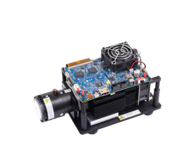
Figure 6 shows the final setup of all parts.
12
Using the DLP4710EVM-LC Light Control Evaluation Module
Copyright © 2019, Texas Instruments Incorporated
DLPU079A – February 2019 – Revised July 2019
Submit Documentation Feedback
�EVM Setup
www.ti.com
Figure 6. DLP4710 Light Control EVM
CAUTION
Make sure to follow all of the initialization procedures listed in this document
before connecting the power. Verify that the DMD flex cable is connected
correctly to the DLP4710 Light Control board.
DLPU079A – February 2019 – Revised July 2019
Submit Documentation Feedback
Using the DLP4710EVM-LC Light Control Evaluation Module
Copyright © 2019, Texas Instruments Incorporated
13
�Revision History
www.ti.com
Revision History
NOTE: Page numbers for previous revisions may differ from page numbers in the current version.
Changes from Original (February 2019) to A Revision .................................................................................................. Page
•
•
•
14
Added throw ratio for optical engine .................................................................................................... 6
Added note on ensuring 1080p input source resolution for pattern streaming modes ........................................... 8
Added ground pin details on connector for LC triggers ............................................................................. 10
Revision History
DLPU079A – February 2019 – Revised July 2019
Submit Documentation Feedback
Copyright © 2019, Texas Instruments Incorporated
�IMPORTANT NOTICE AND DISCLAIMER
TI PROVIDES TECHNICAL AND RELIABILITY DATA (INCLUDING DATASHEETS), DESIGN RESOURCES (INCLUDING REFERENCE
DESIGNS), APPLICATION OR OTHER DESIGN ADVICE, WEB TOOLS, SAFETY INFORMATION, AND OTHER RESOURCES “AS IS”
AND WITH ALL FAULTS, AND DISCLAIMS ALL WARRANTIES, EXPRESS AND IMPLIED, INCLUDING WITHOUT LIMITATION ANY
IMPLIED WARRANTIES OF MERCHANTABILITY, FITNESS FOR A PARTICULAR PURPOSE OR NON-INFRINGEMENT OF THIRD
PARTY INTELLECTUAL PROPERTY RIGHTS.
These resources are intended for skilled developers designing with TI products. You are solely responsible for (1) selecting the appropriate
TI products for your application, (2) designing, validating and testing your application, and (3) ensuring your application meets applicable
standards, and any other safety, security, or other requirements. These resources are subject to change without notice. TI grants you
permission to use these resources only for development of an application that uses the TI products described in the resource. Other
reproduction and display of these resources is prohibited. No license is granted to any other TI intellectual property right or to any third
party intellectual property right. TI disclaims responsibility for, and you will fully indemnify TI and its representatives against, any claims,
damages, costs, losses, and liabilities arising out of your use of these resources.
TI’s products are provided subject to TI’s Terms of Sale (www.ti.com/legal/termsofsale.html) or other applicable terms available either on
ti.com or provided in conjunction with such TI products. TI’s provision of these resources does not expand or otherwise alter TI’s applicable
warranties or warranty disclaimers for TI products.
Mailing Address: Texas Instruments, Post Office Box 655303, Dallas, Texas 75265
Copyright © 2019, Texas Instruments Incorporated
�