DLPC910
DLPC910
DLPS064D – SEPTEMBER 2015 – REVISED SEPTEMBER
2020
DLPS064D – SEPTEMBER 2015 – REVISED SEPTEMBER 2020
www.ti.com
DLPC910 Digital DMD Controller
1 Features
•
•
•
•
•
•
•
•
•
Operates the following DLP ® DMD Chips
– DLP9000X DMD
– DLP9000XUV DMD
– DLP6500 DMD
User-selectable input clock rate
– 400 MHz or 480 MHz with the DLP9000X and
DLP9000XUV
– 400 MHz with the DLP6500
Continuous streaming input data
– Up to 61 gigabits per second with the
DLP9000X and DLP9000XUV
– Up to 24 gigabits per second with the DLP6500
Enables high-speed pattern rates
– Up to 15 kHz binary patterns per second with
the DLP9000X and DLP9000XUV
– Up to 11.5 kHz binary patterns per second with
the DLP6500
8-Bit gray scale pattern rates
– Up to 1.8 kHz with the DLP9000X and
DLP9000XUV with modulated illumination
– Up to 1.4 kHz with the DLP6500 with
modulated illumination
64-Bit 2x LVDS data bus interface
Random DMD row addressing and Load4 loading
Compatible with a variety of user-defined
application processors or FPGAs
I2C interface for control and status queries
3 Description
The DLPC910 is a digital controller for three DMDs:
the DLP9000X, DLP9000XUV, and DLP6500. The
DLPC910 provides customers a high-speed data and
control interface for the DMD to enable binary pattern
rates up to 15 kHz with the DLP9000X/DLP9000XUV
DMDs, and 11.5 kHz with the DLP6500 DMD. These
fast pattern rates set DLP technology apart from other
spatial light modulators and offer customers a
strategic advantage for equipment needing fast,
accurate, and programmable light steering capability.
The DLPC910 provides the required mirror clocking
pulses and timing information to the DMD. The unique
capability and value offered by the DLPC910 device
makes it well suited to support a wide variety of
lithography, industrial, and advanced display
applications.
In DLP-based electronics solutions, image data is
100% digital from the DLPC910 input port to the
projected image. The image stays in digital form and
is never converted into an analog signal. The
DLPC910 processes the digital input image and
converts the data into a format needed by the DMD
for proper display. The DMD then steers the light to
the location determined by the pixel data loaded into
the DMD.
For complete electrical and mechanical specifications
of the DLPC910, see the Virtex®-5 product
specification at www.xilinx.com.
Device Information (1)
2 Applications
•
•
•
Lithography
– Direct imaging
– Flat panel display
– Printed circuit board manufacturing
Industrial
– 3D printing
– 3D scanners for machine vision
– Quality control
Displays
– 3D imaging
– Augmented reality and information overlay
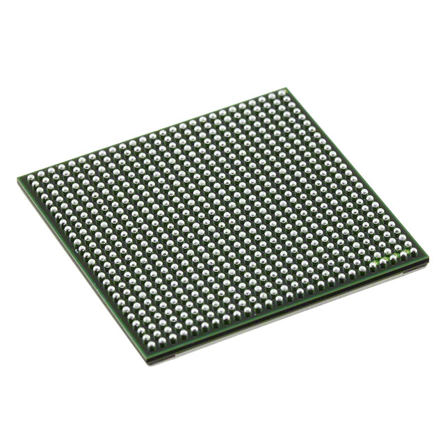
PART NUMBER
DLPC910
(1)
PACKAGE
FCBGA (676)
BODY SIZE (NOM)
27.00 mm × 27.00 mm
For all available packages, see the orderable addendum at
the end of the data sheet.
Typical Application Diagram
An IMPORTANT NOTICE at the end of this data sheet addresses availability, warranty, changes, use in safety-critical applications,
Submit Document Feedback
Copyright
© 2020 Texas
Instruments
Incorporated
intellectual
property
matters
and other important disclaimers. PRODUCTION DATA.
1
�DLPC910
www.ti.com
DLPS064D – SEPTEMBER 2015 – REVISED SEPTEMBER 2020
Table of Contents
1 Features............................................................................1
2 Applications..................................................................... 1
3 Description.......................................................................1
4 Revision History.............................................................. 2
5 Pin Configuration and Functions...................................4
Pin Functions.................................................................... 5
6 Specifications................................................................ 15
6.1 Absolute Maximum Ratings...................................... 15
6.2 ESD Ratings............................................................. 15
6.3 Recommended Operating Conditions.......................15
6.4 Thermal Information..................................................16
6.5 Electrical Characteristics...........................................16
6.6 Timing Requirements................................................ 16
7 Detailed Description......................................................18
7.1 Overview................................................................... 18
7.2 Functional Block Diagram......................................... 18
7.3 Feature Description...................................................18
7.4 Device Functional Modes..........................................26
7.5 Register Map.............................................................40
8 Application and Implementation.................................. 47
8.1 Application Information............................................. 47
8.2 Typical Application.................................................... 47
9 Power Supply Recommendations................................52
9.1 Power Supply Distribution and Requirements.......... 52
9.2 Power Down Requirements...................................... 52
10 Layout...........................................................................53
10.1 Layout Guidelines................................................... 53
10.2 Layout Example...................................................... 57
11 Device and Documentation Support..........................59
11.1 Device Support........................................................59
11.2 Documentation Support.......................................... 59
11.3 Support Resources................................................. 59
11.4 Trademarks............................................................. 59
11.5 Electrostatic Discharge Caution.............................. 60
11.6 Glossary.................................................................. 60
12 Mechanical, Packaging, and Orderable
Information.................................................................... 60
4 Revision History
Changes from Revision C (March 2020) to Revision D (September 2020)
Page
• Updated Description section for DDC_DCLK_(A,B,C,D)_DP(N,P), DDC_DIN_(A,B,C,D)(1-15)_DP(N,P), and
DVALID_(A,B,C,D)_DP(N,P) from "100-Ω internal LVDS termination." to "100-Ω external LVDS termination
required...............................................................................................................................................................5
• Updated I/O Type section for LOAD4_ENZ from LVCMOS33_I to LVCMOS25_I.............................................. 5
• Updated I/O Type section for DMD_IRQ from LVCMOS33_O to LVCMOS25_O...............................................5
• Corrected HBM and CDM values. ................................................................................................................... 15
• Corrected "...during which time RST_ACTIVE is asserted." to "...during which time RST_ACTIVE is NOT
asserted."..........................................................................................................................................................21
• Updated section name from "DMD Power Down" to "DMD Mirror Float". Removed outdated information about
power down...................................................................................................................................................... 21
• Removed "After PWR_FLOAT is asserted, a Mirror Clocking Pulse is issued, or a mirror Float operation is
requested" ........................................................................................................................................................23
• Updated I2C terminology to "primary" and "secondary" throughout section. ................................................... 24
• Updated performance plot for DLP6500 DMD (Figure 8-4) ............................................................................. 50
• Updated performance plot for DLP9000X/DLP9000XUV DMD (Figure 8-3).................................................... 50
Changes from Revision B (November 2016) to Revision C (March 2020)
Page
• Changed title from DLPC910 Digital Controller to DLPC910 Digital DMD Controller ........................................1
• Added new DLP9000XUV DMD as DLPC910 supported DMD (multiple places).............................................. 1
• Updated "DDC_IIC_x" signal names to "DDC_I2C_x" in multiple locations....................................................... 5
• Added missing DLPC_DOUTBUSY pin to complete the listing of all 676 pins of DLPC910.............................. 5
• Added missing unconnected pins to complete the listing of all 676 pins of DLPC910....................................... 5
• Corrected signal name RESETZ to RESET_RSTZ ......................................................................................... 18
• Deleted package code FLS from DMD callout for readability .......................................................................... 18
• Added section describing DDC_Version output pins ....................................................................................... 23
• Corrected I2C version from 1.0-1995 to 1.0-1992. ...........................................................................................24
• Combined Figure 8 and Figure 9 into new Figure 7-6 to incorporate Application Note/Tech Advisory dlpa092
(DLPC910 / DLPR910A - Continuous Row Command Operation). .................................................................34
2
Submit Document Feedback
Copyright © 2020 Texas Instruments Incorporated
�www.ti.com
•
•
•
•
•
•
•
DLPC910
DLPS064D – SEPTEMBER 2015 – REVISED SEPTEMBER 2020
Added DLP9000XUV to DMD Characteristics Table ....................................................................................... 35
Changed "Connected DMD ID" to "Connected DMD TYPE" to match nomenclature of DMD_TYPE_[3:0] input
pins .................................................................................................................................................................. 40
Added explanation that DDC_VERSION_(2:0) output values are mirrored in DESTOP_VERSION register... 43
Corrected signal name RESETZ to RESET_RSTZ in DLP9000X block diagram ........................................... 47
Corrected signal name RESETZ to RESET_RSTZ in DLP6500 block diagram ..............................................47
Added DLP9000XUV to Figure 9-1 - changed previous sentence to clarify one DMD per DLPC910/DLPR910.
..........................................................................................................................................................................52
Added DLP9000XUV link to Related Documentation section ..........................................................................59
Changes from Revision A (October 2015) to Revision B (November 2016)
Page
• Simplified datasheet title.....................................................................................................................................1
• Added family of supported DMDs in Section 1 .................................................................................................. 1
• Updated supply current values in Section 6.5. ................................................................................................ 16
• Indicated how SPEED_SEL should be set when DLP6500 is used in Section 7.3.2 ...................................... 18
• Added reference to the Section 9.2 in Section 7.3.6.4 .................................................................................... 21
• Replaced DMD part number and row count with variable VRes in Section 7.3.6.5.1 ......................................22
• Indicated how SPEED_SEL should be set when DLP6500 is used in Section 7.3.10.3 ................................. 25
• Added cross reference to Table 7-11 in Section 7.4 ........................................................................................ 26
• Added cross reference to Table 7-11 in Section 7.4.1 ..................................................................................... 26
• Added pixel mapping tables for both DMDs in Section 7.4.1 ...........................................................................26
• Added single row write example for the DLP6500 in Section 7.4.1.1 .............................................................. 34
• Added DLP6500 to Table 7-11 .........................................................................................................................35
• Added the number of row cycles required to clear the entire DMD for the DLP6500 in Section 7.4.3 ............ 37
• Added DLP6500 to Table 7-13 .........................................................................................................................37
• Added cross reference to Table 7-11 in Section 7.4.4 ..................................................................................... 37
• Added additional description for activating buses in Section 7.5.1.9 ...............................................................45
• Added DLP6500 DMD to application details to Section 8.2 .............................................................................47
• Added cross reference to Table 7-11 in Section 8.2.1.1 .................................................................................. 49
• Replaced references to part numbers with DMD in Section 8.2.1.2 ................................................................ 49
• Associated performance plot with appropriate DMD (Figure 8-3).....................................................................50
• Added performance plot for DLP6500 DMD (Figure 8-4)................................................................................. 50
• Added power down requirements and increased the minimum 300 µs to 500 µs for maintaining power levels
in Section 9.2 ................................................................................................................................................... 52
• Added Table 9-1, Figure 9-2, Figure 9-3 ..........................................................................................................52
Changes from Revision * (September 2015) to Revision A (October 2015)
Page
• Changed the device from: Product Preview to Production Data.........................................................................1
Copyright © 2020 Texas Instruments Incorporated
Submit Document Feedback
3
�DLPC910
www.ti.com
DLPS064D – SEPTEMBER 2015 – REVISED SEPTEMBER 2020
5 Pin Configuration and Functions
Figure 5-1. ZYR Package 676-Pin FCBGA Top View
4
Submit Document Feedback
Copyright © 2020 Texas Instruments Incorporated
�DLPC910
www.ti.com
DLPS064D – SEPTEMBER 2015 – REVISED SEPTEMBER 2020
I/O Type Descriptions
I/O TYPE
DESCRIPTION
PWR
Power
GND
Ground
LVDS_25_NI
LVDS 2.5-V negative input
LVDS_25_PI
LVDS 2.5-V positive input
LVDS_25_NO
LVDS 2.5-V negative output
LVDS_25_PO
LVDS 2.5-V positive output
LVCMOS25_I
LVCMOS 2.5-V input
LVCMOS25_O
LVCMOS 2.5-V output
LVCMOS25_B
LVCMOS 2.5-V bidirectional
LVCMOS33_I
LVCMOS 3.3-V input
LVCMOS33_O
LVCMOS 3.3-V output
LVCMOS33_B
LVCMOS 3.3-V bidirectional
LVDCI_33_O
Low-voltage digitally controlled impedance 3.3-V output
NC
No connection
Pin Functions
PIN
NAME
CTRL_RSTZ
NO.
F9
I/O TYPE
ACTIVE
(HI OR LO)
CLOCK SYSTEM
LVCMOS25_I
Lo = 0
-
DLPC910 Reset.
DESCRIPTION
AA10
LVCMOS33_I
Hi = 1
-
DLPC910 Secondary I2C Address Lo =
0x34, Hi = 0x36. Includes Internal pull-up.
DDC_I2C_SCL
Y8
LVCMOS33_B
-
-
DLPC910 Secondary I2C Clock.
Requires an external 1-kΩ pull-up
resistor.
DDC_I2C_SDA
AA8
LVCMOS33_B
-
DDC_I2C_SCL
DLPC910 Secondary I2C Data. Requires
an external 1-kΩ pull-up resistor.
DDC_I2C_ADDR_SEL
CLKIN_R
E10
LVCMOS25_I
-
Reference clock
50-MHz Reference Clock
RESET_ADDR0
AD18
LVDCI_33_O
Hi
-
Connect to DMD RESET_ADDR0
RESET_ADDR1
AC18
LVDCI_33_O
Hi
-
Connect to DMD RESET_ADDR1
RESET_ADDR2
AC17
LVDCI_33_O
Hi
-
Connect to DMD RESET_ADDR2
RESET_ADDR3
AC16
LVDCI_33_O
Hi
-
Connect to DMD RESET_ADDR3
RESET_MODE0
AC13
LVDCI_33_O
Hi
-
Connect to DMD RESET_MODE0
RESET_MODE1
AD13
LVDCI_33_O
Hi
-
Connect to DMD RESET_MODE1
RESET_SEL0
AD15
LVDCI_33_O
Hi
-
Connect to DMD RESET_SEL0
RESET_SEL1
AC14
LVDCI_33_O
Hi
-
Connect to DMD RESET_SEL1
RESET_STROBE
AD10
LVDCI_33_O
Hi
-
Connect to DMD RESET_STROBE
RESET_OEZ
AD14
LVDCI_33_O
Lo
-
Connect to DMD RESET_OEZ
RESET_IRQZ
AD8
LVCMOS33_I
Lo
-
Connect to DMD RESET_IRQZ
RESET_RSTZ
AB10
LVDCI_33_O
Lo
-
Connect to DMD PWRDNZ and RESETZ
inputs
SCPCLK
AC7
LVDCI_33_O
-
-
Connect to DMD SCP_CLK
SCPDI
AC8
LVCMOS33_I
-
SCPCLK
Connect to DMD SCP_DO
SCPDO
AC9
LVDCI_33_O
-
SCPCLK
Connect to DMD SCP_DI
DMD_SCPENZ
AB9
LVDCI_33_O
Lo
SCPCLK
Connect to DMD SCP_ENZ
DMD_TYPE_0
G11
LVCMOS25_O
Hi
-
Attached DMD Type bit 0
DMD_TYPE_1
G12
LVCMOS25_O
Hi
-
Attached DMD Type bit 1
DMD_TYPE_2
H11
LVCMOS25_O
Hi
-
Attached DMD Type bit 2
DMD_TYPE_3
H12
LVCMOS25_O
Hi
-
Attached DMD Type bit 3
BLKAD_0
E12
LVCMOS25_I
Hi
DDC_DCLK_[A,B,C,D]
Block Address bit 0
BLKAD_1
D13
LVCMOS25_I
Hi
DDC_DCLK_[A,B,C,D]
Block Address bit 1
BLKAD_2
E13
LVCMOS25_I
Hi
DDC_DCLK_[A,B,C,D]
Block Address bit 2
BLKAD_3
F13
LVCMOS25_I
Hi
DDC_DCLK_[A,B,C,D]
Block Address bit 3
BLKMD_0
H13
LVCMOS25_I
Hi
DDC_DCLK_[A,B,C,D]
Block Mode Bit 0
Copyright © 2020 Texas Instruments Incorporated
Submit Document Feedback
5
�DLPC910
www.ti.com
DLPS064D – SEPTEMBER 2015 – REVISED SEPTEMBER 2020
PIN
6
I/O TYPE
ACTIVE
(HI OR LO)
CLOCK SYSTEM
H14
LVCMOS25_I
Hi
DDC_DCLK_[A,B,C,D]
Block Mode Bit 1
D14
LVCMOS25_I
Hi
-
DMD Row Address bit 0
ROWAD_1
D15
LVCMOS25_I
Hi
-
DMD Row Address bit 1
ROWAD_2
E15
LVCMOS25_I
Hi
-
DMD Row Address bit 2
ROWAD_3
F14
LVCMOS25_I
Hi
-
DMD Row Address bit 3
ROWAD_4
G14
LVCMOS25_I
Hi
-
DMD Row Address bit 4
ROWAD_5
E16
LVCMOS25_I
Hi
-
DMD Row Address bit 5
ROWAD_6
F15
LVCMOS25_I
Hi
-
DMD Row Address bit 6
ROWAD_7
G15
LVCMOS25_I
Hi
-
DMD Row Address bit 7
ROWAD_8
E17
LVCMOS25_I
Hi
-
DMD Row Address bit 8
ROWAD_9
F17
LVCMOS25_I
Hi
-
DMD Row Address bit 9
ROWAD_10
G16
LVCMOS25_I
Hi
-
DMD Row Address bit 10
ROWMD_0
H17
LVCMOS25_I
Hi
-
DMD Row Mode bit 0
ROWMD_1
H16
LVCMOS25_I
Hi
-
DMD Row Mode bit 1
DDC_DCLK_A_DPN
B21
LVDS_25_NI
-
-
DDC_DCLK_A_DPP
C21
LVDS_25_PI
-
-
Input Bus A Clock. 100-Ω external LVDS
termination required.
DDC_DCLK_B_DPN
A7
LVDS_25_NI
-
-
DDC_DCLK_B_DPP
B7
LVDS_25_PI
-
-
DDC_DCLK_C_DPN
K20
LVDS_25_NI
-
-
DDC_DCLK_C_DPP
K21
LVDS_25_PI
-
-
DDC_DCLK_D_DPN
L5
LVDS_25_NI
-
-
DDC_DCLK_D_DPP
K5
LVDS_25_PI
-
-
DDC_DCLKOUT_A_DPN
N1
LVDS_25_NO
-
-
DDC_DCLKOUT_A_DPP
M1
LVDS_25_PO
-
-
DDC_DCLKOUT_B_DPN
Y5
LVDS_25_NO
-
-
DDC_DCLKOUT_B_DPP
Y6
LVDS_25_PO
-
-
DDC_DCLKOUT_C_DPN
AA22
LVDS_25_NO
-
-
DDC_DCLKOUT_C_DPP
AB22
LVDS_25_PO
-
-
DDC_DCLKOUT_D_DPN
M26
LVDS_25_NO
-
-
DDC_DCLKOUT_D_DPP
M25
LVDS_25_PO
-
-
DDC_DIN_A0_DPN
A15
LVDS_25_NI
-
DDC_DCLK_A
DDC_DIN_A0_DPP
A14
LVDS_25_PI
-
DDC_DCLK_A
DDC_DIN_A1_DPN
B14
LVDS_25_NI
-
DDC_DCLK_A
DDC_DIN_A1_DPP
C14
LVDS_25_PI
-
DDC_DCLK_A
DDC_DIN_A2_DPN
B16
LVDS_25_NI
-
DDC_DCLK_A
NAME
NO.
BLKMD_1
ROWAD_0
DESCRIPTION
Input Bus B Clock. 100-Ω external LVDS
termination required.
Input Bus C Clock. 100-Ω external LVDS
termination required.
Input Bus D Clock. 100-Ω external LVDS
termination required.
Output Bus A Clock to DMD.
Output Bus B Clock to DMD.
Output Bus C Clock to DMD.
Output Bus D Clock to DMD.
DDC_DIN_A2_DPP
B15
LVDS_25_PI
-
DDC_DCLK_A
DDC_DIN_A3_DPN
C16
LVDS_25_NI
-
DDC_DCLK_A
DDC_DIN_A3_DPP
D16
LVDS_25_PI
-
DDC_DCLK_A
DDC_DIN_A4_DPN
A17
LVDS_25_NI
-
DDC_DCLK_A
DDC_DIN_A4_DPP
B17
LVDS_25_PI
-
DDC_DCLK_A
DDC_DIN_A5_DPN
C17
LVDS_25_NI
-
DDC_DCLK_A
DDC_DIN_A5_DPP
D18
LVDS_25_PI
-
DDC_DCLK_A
DDC_DIN_A6_DPN
A19
LVDS_25_NI
-
DDC_DCLK_A
Input Bus A Data bit 0.
100-Ω external LVDS termination
required.
Input Bus A Data bit 1.
100-Ω external LVDS termination
required.
Input Bus A Data bit 2.
100-Ω external LVDS termination
required.
Input Bus A Data bit 3.
100-Ω external LVDS termination
required.
Input Bus A Data bit 4.
100-Ω external LVDS termination
required.
Input Bus A Data bit 5.
100-Ω external LVDS termination
required.
Input Bus A Data bit 6.
100-Ω external LVDS termination
required.
DDC_DIN_A6_DPP
A18
LVDS_25_PI
-
DDC_DCLK_A
DDC_DIN_A7_DPN
C18
LVDS_25_NI
-
DDC_DCLK_A
DDC_DIN_A7_DPP
B19
LVDS_25_PI
-
DDC_DCLK_A
DDC_DIN_A8_DPN
D19
LVDS_25_NI
-
DDC_DCLK_A
DDC_DIN_A8_DPP
C19
LVDS_25_PI
-
DDC_DCLK_A
DDC_DIN_A9_DPN
B20
LVDS_25_NI
-
DDC_DCLK_A
DDC_DIN_A9_DPP
A20
LVDS_25_PI
-
DDC_DCLK_A
DDC_DIN_A10_DPN
A22
LVDS_25_NI
-
DDC_DCLK_A
DDC_DIN_A10_DPP
B22
LVDS_25_PI
-
DDC_DCLK_A
Input Bus A Data bit 10.
100-Ω external LVDS termination
required.
DDC_DIN_A11_DPN
A24
LVDS_25_NI
-
DDC_DCLK_A
Input Bus A Data bit 11.
Submit Document Feedback
Input Bus A Data bit 7.
100-Ω external LVDS termination
required.
Input Bus A Data bit 8.
100-Ω external LVDS termination
required.
Input Bus A Data bit 9.
100-Ω external LVDS termination
required.
Copyright © 2020 Texas Instruments Incorporated
�DLPC910
www.ti.com
DLPS064D – SEPTEMBER 2015 – REVISED SEPTEMBER 2020
PIN
I/O TYPE
ACTIVE
(HI OR LO)
CLOCK SYSTEM
DESCRIPTION
A23
LVDS_25_PI
-
DDC_DCLK_A
100-Ω external LVDS termination
required.
DDC_DIN_A12_DPN
C23
LVDS_25_NI
-
DDC_DCLK_A
DDC_DIN_A12_DPP
B24
LVDS_25_PI
-
DDC_DCLK_A
DDC_DIN_A13_DPN
C24
LVDS_25_NI
-
DDC_DCLK_A
DDC_DIN_A13_DPP
D24
LVDS_25_PI
-
DDC_DCLK_A
DDC_DIN_A14_DPN
A25
LVDS_25_NI
-
DDC_DCLK_A
DDC_DIN_A14_DPP
B25
LVDS_25_PI
-
DDC_DCLK_A
DDC_DIN_A15_DPN
C26
LVDS_25_NI
-
DDC_DCLK_A
DDC_DIN_A15_DPP
B26
LVDS_25_PI
-
DDC_DCLK_A
DDC_DIN_B0_DPN
A12
LVDS_25_NI
-
DDC_DCLK_B
DDC_DIN_B0_DPP
A13
LVDS_25_PI
-
DDC_DCLK_B
DDC_DIN_B1_DPN
B12
LVDS_25_NI
-
DDC_DCLK_B
DDC_DIN_B1_DPP
C13
LVDS_25_PI
-
DDC_DCLK_B
DDC_DIN_B2_DPN
D10
LVDS_25_NI
-
DDC_DCLK_B
NAME
NO.
DDC_DIN_A11_DPP
DDC_DIN_B2_DPP
D11
LVDS_25_PI
-
DDC_DCLK_B
DDC_DIN_B3_DPN
C12
LVDS_25_NI
-
DDC_DCLK_B
DDC_DIN_B3_DPP
C11
LVDS_25_PI
-
DDC_DCLK_B
DDC_DIN_B4_DPN
A10
LVDS_25_NI
-
DDC_DCLK_B
DDC_DIN_B4_DPP
B11
LVDS_25_PI
-
DDC_DCLK_B
DDC_DIN_B5_DPN
D9
LVDS_25_NI
-
DDC_DCLK_B
DDC_DIN_B5_DPP
C9
LVDS_25_PI
-
DDC_DCLK_B
DDC_DIN_B6_DPN
B10
LVDS_25_NI
-
DDC_DCLK_B
DDC_DIN_B6_DPP
B9
LVDS_25_PI
-
DDC_DCLK_B
DDC_DIN_B7_DPN
A8
LVDS_25_NI
-
DDC_DCLK_B
DDC_DIN_B7_DPP
A9
LVDS_25_PI
-
DDC_DCLK_B
DDC_DIN_B8_DPN
D6
LVDS_25_NI
-
DDC_DCLK_B
DDC_DIN_B8_DPP
D5
LVDS_25_PI
-
DDC_DCLK_B
DDC_DIN_B9_DPN
C7
LVDS_25_NI
-
DDC_DCLK_B
DDC_DIN_B9_DPP
C6
LVDS_25_PI
-
DDC_DCLK_B
DDC_DIN_B10_DPN
B6
LVDS_25_NI
-
DDC_DCLK_B
DDC_DIN_B10_DPP
B5
LVDS_25_PI
-
DDC_DCLK_B
DDC_DIN_B11_DPN
D4
LVDS_25_NI
-
DDC_DCLK_B
DDC_DIN_B11_DPP
D3
LVDS_25_PI
-
DDC_DCLK_B
DDC_DIN_B12_DPN
B4
LVDS_25_NI
-
DDC_DCLK_B
DDC_DIN_B12_DPP
C4
LVDS_25_PI
-
DDC_DCLK_B
DDC_DIN_B13_DPN
C3
LVDS_25_NI
-
DDC_DCLK_B
DDC_DIN_B13_DPP
C2
LVDS_25_PI
-
DDC_DCLK_B
DDC_DIN_B14_DPN
A3
LVDS_25_NI
-
DDC_DCLK_B
DDC_DIN_B14_DPP
A2
LVDS_25_PI
-
DDC_DCLK_B
DDC_DIN_B15_DPN
B2
LVDS_25_NI
-
DDC_DCLK_B
DDC_DIN_B15_DPP
B1
LVDS_25_PI
-
DDC_DCLK_B
DDC_DIN_C0_DPN
E20
LVDS_25_NI
-
DDC_DCLK_C
DDC_DIN_C0_DPP
E21
LVDS_25_PI
-
DDC_DCLK_C
DDC_DIN_C1_DPN
F20
LVDS_25_NI
-
DDC_DCLK_C
DDC_DIN_C1_DPP
G20
LVDS_25_PI
-
DDC_DCLK_C
DDC_DIN_C2_DPN
H19
LVDS_25_NI
-
DDC_DCLK_C
Input Bus A Data bit 12.
100-Ω external LVDS termination
required.
Input Bus A Data bit 13.
100-Ω external LVDS termination
required.
Input Bus A Data bit 14.
100-Ω external LVDS termination
required.
Input Bus A Data bit 15.
100-Ω external LVDS termination
required.
Input Bus B Data bit 0.
100-Ω external LVDS termination
required.
Input Bus B Data bit 1.
100-Ω external LVDS termination
required.
Input Bus B Data bit 2.
100-Ω external LVDS termination
required.
Input Bus B Data bit 3.
100-Ω external LVDS termination
required.
Input Bus B Data bit 4.
100-Ω external LVDS termination
required.
Input Bus B Data bit 5.
100-Ω external LVDS termination
required.
Input Bus B Data bit 6.
100-Ω external LVDS termination
required.
Input Bus B Data bit 7.
100-Ω external LVDS termination
required.
Input Bus B Data bit 8.
100-Ω external LVDS termination
required.
Input Bus B Data bit 9.
100-Ω external LVDS termination
required.
Input Bus B Data bit 10.
100-Ω external LVDS termination
required.
Input Bus B Data bit 11.
100-Ω external LVDS termination
required.
Input Bus B Data bit 12.
100-Ω external LVDS termination
required.
Input Bus B Data bit 13.
100-Ω external LVDS termination
required.
Input Bus B Data bit 14.
100-Ω external LVDS termination
required.
Input Bus B Data bit 15.
100-Ω external LVDS termination
required.
Input Bus C Data bit 0.
100-Ω external LVDS termination
required.
Input Bus C Data bit 1.
100-Ω external LVDS termination
required.
DDC_DIN_C2_DPP
J19
LVDS_25_PI
-
DDC_DCLK_C
Input Bus C Data bit 2.
100-Ω external LVDS termination
required.
DDC_DIN_C3_DPN
E23
LVDS_25_NI
-
DDC_DCLK_C
Input Bus C Data bit 3.
Copyright © 2020 Texas Instruments Incorporated
Submit Document Feedback
7
�DLPC910
www.ti.com
DLPS064D – SEPTEMBER 2015 – REVISED SEPTEMBER 2020
PIN
8
I/O TYPE
ACTIVE
(HI OR LO)
CLOCK SYSTEM
DESCRIPTION
E22
LVDS_25_PI
-
DDC_DCLK_C
100-Ω external LVDS termination
required.
DDC_DIN_C4_DPN
F23
LVDS_25_NI
-
DDC_DCLK_C
DDC_DIN_C4_DPP
F22
LVDS_25_PI
-
DDC_DCLK_C
DDC_DIN_C5_DPN
G22
LVDS_25_NI
-
DDC_DCLK_C
DDC_DIN_C5_DPP
G21
LVDS_25_PI
-
DDC_DCLK_C
DDC_DIN_C6_DPN
J20
LVDS_25_NI
-
DDC_DCLK_C
DDC_DIN_C6_DPP
J21
LVDS_25_PI
-
DDC_DCLK_C
DDC_DIN_C7_DPN
H22
LVDS_25_NI
-
DDC_DCLK_C
DDC_DIN_C7_DPP
H21
LVDS_25_PI
-
DDC_DCLK_C
DDC_DIN_C8_DPN
J23
LVDS_25_NI
-
DDC_DCLK_C
DDC_DIN_C8_DPP
H23
LVDS_25_PI
-
DDC_DCLK_C
DDC_DIN_C9_DPN
K22
LVDS_25_NI
-
DDC_DCLK_C
DDC_DIN_C9_DPP
K23
LVDS_25_PI
-
DDC_DCLK_C
DDC_DIN_C10_DPN
M19
LVDS_25_NI
-
DDC_DCLK_C
DDC_DIN_C10_DPP
M20
LVDS_25_PI
-
DDC_DCLK_C
DDC_DIN_C11_DPN
M21
LVDS_25_NI
-
DDC_DCLK_C
DDC_DIN_C11_DPP
M22
LVDS_25_PI
-
DDC_DCLK_C
DDC_DIN_C12_DPN
N19
LVDS_25_NI
-
DDC_DCLK_C
NAME
NO.
DDC_DIN_C3_DPP
DDC_DIN_C12_DPP
P19
LVDS_25_PI
-
DDC_DCLK_C
DDC_DIN_C13_DPN
N21
LVDS_25_NI
-
DDC_DCLK_C
DDC_DIN_C13_DPP
N22
LVDS_25_PI
-
DDC_DCLK_C
DDC_DIN_C14_DPN
P20
LVDS_25_NI
-
DDC_DCLK_C
DDC_DIN_C14_DPP
P21
LVDS_25_PI
-
DDC_DCLK_C
DDC_DIN_C15_DPN
N23
LVDS_25_NI
-
DDC_DCLK_C
DDC_DIN_C15_DPP
P23
LVDS_25_PI
-
DDC_DCLK_C
DDC_DIN_D0_DPN
T3
LVDS_25_NI
-
DDC_DCLK_D
DDC_DIN_D0_DPP
R3
LVDS_25_PI
-
DDC_DCLK_D
DDC_DIN_D1_DPN
R5
LVDS_25_NI
-
DDC_DCLK_D
DDC_DIN_D1_DPP
R6
LVDS_25_PI
-
DDC_DCLK_D
DDC_DIN_D2_DPN
R7
LVDS_25_NI
-
DDC_DCLK_D
DDC_DIN_D2_DPP
P6
LVDS_25_PI
-
DDC_DCLK_D
DDC_DIN_D3_DPN
N3
LVDS_25_NI
-
DDC_DCLK_D
DDC_DIN_D3_DPP
P3
LVDS_25_PI
-
DDC_DCLK_D
DDC_DIN_D4_DPN
P4
LVDS_25_NI
-
DDC_DCLK_D
DDC_DIN_D4_DPP
P5
LVDS_25_PI
-
DDC_DCLK_D
DDC_DIN_D5_DPN
N6
LVDS_25_NI
-
DDC_DCLK_D
DDC_DIN_D5_DPP
N7
LVDS_25_PI
-
DDC_DCLK_D
DDC_DIN_D6_DPN
N4
LVDS_25_NI
-
DDC_DCLK_D
DDC_DIN_D6_DPP
M4
LVDS_25_PI
-
DDC_DCLK_D
DDC_DIN_D7_DPN
M7
LVDS_25_NI
-
DDC_DCLK_D
DDC_DIN_D7_DPP
L7
LVDS_25_PI
-
DDC_DCLK_D
DDC_DIN_D8_DPN
K7
LVDS_25_NI
-
DDC_DCLK_D
DDC_DIN_D8_DPP
K6
LVDS_25_PI
-
DDC_DCLK_D
DDC_DIN_D9_DPN
J4
LVDS_25_NI
-
DDC_DCLK_D
DDC_DIN_D9_DPP
J5
LVDS_25_PI
-
DDC_DCLK_D
DDC_DIN_D10_DPN
H7
LVDS_25_NI
-
DDC_DCLK_D
DDC_DIN_D10_DPP
J6
LVDS_25_PI
-
DDC_DCLK_D
DDC_DIN_D11_DPN
G4
LVDS_25_NI
-
DDC_DCLK_D
DDC_DIN_D11_DPP
H4
LVDS_25_PI
-
DDC_DCLK_D
Submit Document Feedback
Input Bus C Data bit 4.
100-Ω external LVDS termination
required.
Input Bus C Data bit 5.
100-Ω external LVDS termination
required.
Input Bus C Data bit 6.
100-Ω external LVDS termination
required.
Input Bus C Data bit 7.
100-Ω external LVDS termination
required.
Input Bus C Data bit 8.
100-Ω external LVDS termination
required.
Input Bus C Data bit 9.
100-Ω external LVDS termination
required.
Input Bus C Data bit 10.
100-Ω external LVDS termination
required.
Input Bus C Data bit 11.
100-Ω external LVDS termination
required.
Input Bus C Data bit 12.
100-Ω external LVDS termination
required.
Input Bus C Data bit 13.
100-Ω external LVDS termination
required.
Input Bus C Data bit 14.
100-Ω external LVDS termination
required.
Input Bus C Data bit 15.
100-Ω external LVDS termination
required.
Input Bus D Data bit 0.
100-Ω external LVDS termination
required.
Input Bus D Data bit 1.
100-Ω external LVDS termination
required.
Input Bus D Data bit 2.
100-Ω external LVDS termination
required.
Input Bus D Data bit 3.
100-Ω external LVDS termination
required.
Input Bus D Data bit 4.
100-Ω external LVDS termination
required.
Input Bus D Data bit 5.
100-Ω external LVDS termination
required.
Input Bus D Data bit 6.
100-Ω external LVDS termination
required.
Input Bus D Data bit 7.
100-Ω external LVDS termination
required.
Input Bus D Data bit 8.
100-Ω external LVDS termination
required.
Input Bus D Data bit 9.
100-Ω external LVDS termination
required.
Input Bus D Data bit 10.
100-Ω external LVDS termination
required.
Input Bus D Data bit 11.
100-Ω external LVDS termination
required.
Copyright © 2020 Texas Instruments Incorporated
�DLPC910
www.ti.com
DLPS064D – SEPTEMBER 2015 – REVISED SEPTEMBER 2020
PIN
I/O TYPE
ACTIVE
(HI OR LO)
CLOCK SYSTEM
DESCRIPTION
G5
LVDS_25_NI
-
DDC_DCLK_D
H6
LVDS_25_PI
-
DDC_DCLK_D
Input Bus D Data bit 12.
100-Ω external LVDS termination
required.
DDC_DIN_D13_DPN
G7
LVDS_25_NI
-
DDC_DCLK_D
DDC_DIN_D13_DPP
G6
LVDS_25_PI
-
DDC_DCLK_D
DDC_DIN_D14_DPN
F4
LVDS_25_NI
-
DDC_DCLK_D
DDC_DIN_D14_DPP
F5
LVDS_25_PI
-
DDC_DCLK_D
DDC_DIN_D15_DPN
E5
LVDS_25_NI
-
DDC_DCLK_D
NAME
NO.
DDC_DIN_D12_DPN
DDC_DIN_D12_DPP
DDC_DIN_D15_DPP
E6
LVDS_25_PI
-
DDC_DCLK_D
DDC_DOUT_A0_DPN
AE2
LVDS_25_NO
-
DDC_DCLKOUT_A
DDC_DOUT_A0_DPP
AF2
LVDS_25_PO
-
DDC_DCLKOUT_A
DDC_DOUT_A1_DPN
AD1
LVDS_25_NO
-
DDC_DCLKOUT_A
DDC_DOUT_A1_DPP
AE1
LVDS_25_PO
-
DDC_DCLKOUT_A
DDC_DOUT_A2_DPN
AC1
LVDS_25_NO
-
DDC_DCLKOUT_A
DDC_DOUT_A2_DPP
AC2
LVDS_25_PO
-
DDC_DCLKOUT_A
DDC_DOUT_A3_DPN
AB1
LVDS_25_NO
-
DDC_DCLKOUT_A
DDC_DOUT_A3_DPP
AB2
LVDS_25_PO
-
DDC_DCLKOUT_A
DDC_DOUT_A4_DPN
Y2
LVDS_25_NO
-
DDC_DCLKOUT_A
DDC_DOUT_A4_DPP
AA2
LVDS_25_PO
-
DDC_DCLKOUT_A
DDC_DOUT_A5_DPN
W1
LVDS_25_NO
-
DDC_DCLKOUT_A
DDC_DOUT_A5_DPP
Y1
LVDS_25_PO
-
DDC_DCLKOUT_A
DDC_DOUT_A6_DPN
V1
LVDS_25_NO
-
DDC_DCLKOUT_A
DDC_DOUT_A6_DPP
V2
LVDS_25_PO
-
DDC_DCLKOUT_A
DDC_DOUT_A7_DPN
U1
LVDS_25_NO
-
DDC_DCLKOUT_A
DDC_DOUT_A7_DPP
U2
LVDS_25_PO
-
DDC_DCLKOUT_A
DDC_DOUT_A8_DPN
R2
LVDS_25_NO
-
DDC_DCLKOUT_A
DDC_DOUT_A8_DPP
T2
LVDS_25_PO
-
DDC_DCLKOUT_A
DDC_DOUT_A9_DPN
N2
LVDS_25_NO
-
DDC_DCLKOUT_A
DDC_DOUT_A9_DPP
M2
LVDS_25_PO
-
DDC_DCLKOUT_A
DDC_DOUT_A10_DPN
K1
LVDS_25_NO
-
DDC_DCLKOUT_A
DDC_DOUT_A10_DPP
L2
LVDS_25_PO
-
DDC_DCLKOUT_A
DDC_DOUT_A11_DPN
K2
LVDS_25_NO
-
DDC_DCLKOUT_A
DDC_DOUT_A11_DPP
K3
LVDS_25_PO
-
DDC_DCLKOUT_A
DDC_DOUT_A12_DPN
J3
LVDS_25_NO
-
DDC_DCLKOUT_A
DDC_DOUT_A12_DPP
H3
LVDS_25_PO
-
DDC_DCLKOUT_A
DDC_DOUT_A13_DPN
H2
LVDS_25_NO
-
DDC_DCLKOUT_A
DDC_DOUT_A13_DPP
J1
LVDS_25_PO
-
DDC_DCLKOUT_A
DDC_DOUT_A14_DPN
H1
LVDS_25_NO
-
DDC_DCLKOUT_A
DDC_DOUT_A14_DPP
G1
LVDS_25_PO
-
DDC_DCLKOUT_A
DDC_DOUT_A15_DPN
G2
LVDS_25_NO
-
DDC_DCLKOUT_A
DDC_DOUT_A15_DPP
F2
LVDS_25_PO
-
DDC_DCLKOUT_A
DDC_DOUT_B0_DPN
AE5
LVDS_25_NO
-
DDC_DCLKOUT_B
DDC_DOUT_B0_DPP
AE6
LVDS_25_PO
-
DDC_DCLKOUT_B
DDC_DOUT_B1_DPN
AD3
LVDS_25_NO
-
DDC_DCLKOUT_B
DDC_DOUT_B1_DPP
AD4
LVDS_25_PO
-
DDC_DCLKOUT_B
DDC_DOUT_B2_DPN
AD5
LVDS_25_NO
-
DDC_DCLKOUT_B
DDC_DOUT_B2_DPP
AD6
LVDS_25_PO
-
DDC_DCLKOUT_B
DDC_DOUT_B3_DPN
AC3
LVDS_25_NO
-
DDC_DCLKOUT_B
DDC_DOUT_B3_DPP
AC4
LVDS_25_PO
-
DDC_DCLKOUT_B
DDC_DOUT_B4_DPN
AB5
LVDS_25_NO
-
DDC_DCLKOUT_B
DDC_DOUT_B4_DPP
AB6
LVDS_25_PO
-
DDC_DCLKOUT_B
DDC_DOUT_B5_DPN
AB7
LVDS_25_NO
-
DDC_DCLKOUT_B
DDC_DOUT_B5_DPP
AC6
LVDS_25_PO
-
DDC_DCLKOUT_B
DDC_DOUT_B6_DPN
AA5
LVDS_25_NO
-
DDC_DCLKOUT_B
DDC_DOUT_B6_DPP
AA4
LVDS_25_PO
-
DDC_DCLKOUT_B
Copyright © 2020 Texas Instruments Incorporated
Input Bus D Data bit 13.
100-Ω external LVDS termination
required.
Input Bus D Data bit 14.
100-Ω external LVDS termination
required.
Input Bus D Data bit 15.
100-Ω external LVDS termination
required.
Output Bus A Data bit 0 to DMD.
Output Bus A Data bit 1 to DMD.
Output Bus A Data bit 2 to DMD.
Output Bus A Data bit 3 to DMD.
Output Bus A Data bit 4 to DMD.
Output Bus A Data bit 5 to DMD.
Output Bus A Data bit 6 to DMD.
Output Bus A Data bit 7 to DMD.
Output Bus A Data bit 8 to DMD.
Output Bus A Data bit 9 to DMD.
Output Bus A Data bit 10 to DMD.
Output Bus A Data bit 11 to DMD.
Output Bus A Data bit 12 to DMD.
Output Bus A Data bit 13 to DMD.
Output Bus A Data bit 14 to DMD.
Output Bus A Data bit 15 to DMD.
Output Bus B Data bit 0 to DMD.
Output Bus B Data bit 1 to DMD.
Output Bus B Data bit 2 to DMD.
Output Bus B Data bit 3 to DMD.
Output Bus B Data bit 4 to DMD.
Output Bus B Data bit 5 to DMD.
Output Bus B Data bit 6 to DMD.
Submit Document Feedback
9
�DLPC910
www.ti.com
DLPS064D – SEPTEMBER 2015 – REVISED SEPTEMBER 2020
PIN
I/O TYPE
ACTIVE
(HI OR LO)
CLOCK SYSTEM
AA7
LVDS_25_NO
-
DDC_DCLKOUT_B
Y7
LVDS_25_PO
-
DDC_DCLKOUT_B
DDC_DOUT_B8_DPN
Y3
LVDS_25_NO
-
DDC_DCLKOUT_B
DDC_DOUT_B8_DPP
W3
LVDS_25_PO
-
DDC_DCLKOUT_B
DDC_DOUT_B9_DPN
W4
LVDS_25_NO
-
DDC_DCLKOUT_B
DDC_DOUT_B9_DPP
V4
LVDS_25_PO
-
DDC_DCLKOUT_B
DDC_DOUT_B10_DPN
W6
LVDS_25_NO
-
DDC_DCLKOUT_B
DDC_DOUT_B10_DPP
W5
LVDS_25_PO
-
DDC_DCLKOUT_B
DDC_DOUT_B11_DPN
V7
LVDS_25_NO
-
DDC_DCLKOUT_B
DDC_DOUT_B11_DPP
V6
LVDS_25_PO
-
DDC_DCLKOUT_B
DDC_DOUT_B12_DPN
U4
LVDS_25_NO
-
DDC_DCLKOUT_B
DDC_DOUT_B12_DPP
V3
LVDS_25_PO
-
DDC_DCLKOUT_B
DDC_DOUT_B13_DPN
T4
LVDS_25_NO
-
DDC_DCLKOUT_B
DDC_DOUT_B13_DPP
T5
LVDS_25_PO
-
DDC_DCLKOUT_B
DDC_DOUT_B14_DPN
U6
LVDS_25_NO
-
DDC_DCLKOUT_B
DDC_DOUT_B14_DPP
U5
LVDS_25_PO
-
DDC_DCLKOUT_B
DDC_DOUT_B15_DPN
U7
LVDS_25_NO
-
DDC_DCLKOUT_B
DDC_DOUT_B15_DPP
T7
LVDS_25_PO
-
DDC_DCLKOUT_B
DDC_DOUT_C0_DPN
T22
LVDS_25_NO
-
DDC_DCLKOUT_C
DDC_DOUT_C0_DPP
T23
LVDS_25_PO
-
DDC_DCLKOUT_C
DDC_DOUT_C1_DPN
R20
LVDS_25_NO
-
DDC_DCLKOUT_C
DDC_DOUT_C1_DPP
R21
LVDS_25_PO
-
DDC_DCLKOUT_C
DDC_DOUT_C2_DPN
T19
LVDS_25_NO
-
DDC_DCLKOUT_C
DDC_DOUT_C2_DPP
T20
LVDS_25_PO
-
DDC_DCLKOUT_C
DDC_DOUT_C3_DPN
U21
LVDS_25_NO
-
DDC_DCLKOUT_C
DDC_DOUT_C3_DPP
U22
LVDS_25_PO
-
DDC_DCLKOUT_C
DDC_DOUT_C4_DPN
U20
LVDS_25_NO
-
DDC_DCLKOUT_C
DDC_DOUT_C4_DPP
U19
LVDS_25_PO
-
DDC_DCLKOUT_C
DDC_DOUT_C5_DPN
V23
LVDS_25_NO
-
DDC_DCLKOUT_C
DDC_DOUT_C5_DPP
V24
LVDS_25_PO
-
DDC_DCLKOUT_C
DDC_DOUT_C6_DPN
V22
LVDS_25_NO
-
DDC_DCLKOUT_C
DDC_DOUT_C6_DPP
V21
LVDS_25_PO
-
DDC_DCLKOUT_C
DDC_DOUT_C7_DPN
W19
LVDS_25_NO
-
DDC_DCLKOUT_C
DDC_DOUT_C7_DPP
V19
LVDS_25_PO
-
DDC_DCLKOUT_C
DDC_DOUT_C8_DPN
W23
LVDS_25_NO
-
DDC_DCLKOUT_C
DDC_DOUT_C8_DPP
W24
LVDS_25_PO
-
DDC_DCLKOUT_C
DDC_DOUT_C9_DPN
Y22
LVDS_25_NO
-
DDC_DCLKOUT_C
DDC_DOUT_C9_DPP
Y23
LVDS_25_PO
-
DDC_DCLKOUT_C
DDC_DOUT_C10_DPN
Y20
LVDS_25_NO
-
DDC_DCLKOUT_C
DDC_DOUT_C10_DPP
Y21
LVDS_25_PO
-
DDC_DCLKOUT_C
DDC_DOUT_C11_DPN
AA24
LVDS_25_NO
-
DDC_DCLKOUT_C
DDC_DOUT_C11_DPP
AA23
LVDS_25_PO
-
DDC_DCLKOUT_C
DDC_DOUT_C12_DPN
AA19
LVDS_25_NO
-
DDC_DCLKOUT_C
DDC_DOUT_C12_DPP
AA20
LVDS_25_PO
-
DDC_DCLKOUT_C
DDC_DOUT_C13_DPN
AC24
LVDS_25_NO
-
DDC_DCLKOUT_C
DDC_DOUT_C13_DPP
AB24
LVDS_25_PO
-
DDC_DCLKOUT_C
DDC_DOUT_C14_DPN
AC19
LVDS_25_NO
-
DDC_DCLKOUT_C
DDC_DOUT_C14_DPP
AD19
LVDS_25_PO
-
DDC_DCLKOUT_C
DDC_DOUT_C15_DPN
AC22
LVDS_25_NO
-
DDC_DCLKOUT_C
DDC_DOUT_C15_DPP
AC23
LVDS_25_PO
-
DDC_DCLKOUT_C
DDC_DOUT_D0_DPN
AB26
LVDS_25_NO
-
DDC_DCLKOUT_D
DDC_DOUT_D0_DPP
AC26
LVDS_25_PO
-
DDC_DCLKOUT_D
DDC_DOUT_D1_DPN
AA25
LVDS_25_NO
-
DDC_DCLKOUT_D
DDC_DOUT_D1_DPP
AB25
LVDS_25_PO
-
DDC_DCLKOUT_D
DDC_DOUT_D2_DPN
Y26
LVDS_25_NO
-
DDC_DCLKOUT_D
NAME
NO.
DDC_DOUT_B7_DPN
DDC_DOUT_B7_DPP
10
Submit Document Feedback
DESCRIPTION
Output Bus B Data bit 7 to DMD.
Output Bus B Data bit 8 to DMD.
Output Bus B Data bit 9 to DMD.
Output Bus B Data bit 10 to DMD.
Output Bus B Data bit 11 to DMD.
Output Bus B Data bit 12 to DMD.
Output Bus B Data bit 13 to DMD.
Output Bus B Data bit 14 to DMD.
Output Bus B Data bit 15 to DMD.
Output Bus C Data bit 0 to DMD.
Output Bus C Data bit 1 to DMD.
Output Bus C Data bit 2 to DMD.
Output Bus C Data bit 3 to DMD.
Output Bus C Data bit 4 to DMD.
Output Bus C Data bit 5 to DMD.
Output Bus C Data bit 6 to DMD.
Output Bus C Data bit 7 to DMD.
Output Bus C Data bit 8 to DMD.
Output Bus C Data bit 9 to DMD.
Output Bus C Data bit 10 to DMD.
Output Bus C Data bit 11 to DMD.
Output Bus C Data bit 12 to DMD.
Output Bus C Data bit 13 to DMD.
Output Bus C Data bit 14 to DMD.
Output Bus C Data bit 15 to DMD.
Output Bus D Data bit 0 to DMD.
Output Bus D Data bit 1 to DMD.
Output Bus D Data bit 2 to DMD.
Copyright © 2020 Texas Instruments Incorporated
�DLPC910
www.ti.com
DLPS064D – SEPTEMBER 2015 – REVISED SEPTEMBER 2020
PIN
NAME
NO.
I/O TYPE
ACTIVE
(HI OR LO)
CLOCK SYSTEM
DDC_DOUT_D2_DPP
Y25
LVDS_25_PO
-
DDC_DCLKOUT_D
DDC_DOUT_D3_DPN
W26
LVDS_25_NO
-
DDC_DCLKOUT_D
DDC_DOUT_D3_DPP
W25
LVDS_25_PO
-
DDC_DCLKOUT_D
DDC_DOUT_D4_DPN
U26
LVDS_25_NO
-
DDC_DCLKOUT_D
DDC_DOUT_D4_DPP
V26
LVDS_25_PO
-
DDC_DCLKOUT_D
DDC_DOUT_D5_DPN
U25
LVDS_25_NO
-
DDC_DCLKOUT_D
DDC_DOUT_D5_DPP
U24
LVDS_25_PO
-
DDC_DCLKOUT_D
DDC_DOUT_D6_DPN
T25
LVDS_25_NO
-
DDC_DCLKOUT_D
DDC_DOUT_D6_DPP
T24
LVDS_25_PO
-
DDC_DCLKOUT_D
DDC_DOUT_D7_DPN
R26
LVDS_25_NO
-
DDC_DCLKOUT_D
DDC_DOUT_D7_DPP
R25
LVDS_25_PO
-
DDC_DCLKOUT_D
DDC_DOUT_D8_DPN
P24
LVDS_25_NO
-
DDC_DCLKOUT_D
DDC_DOUT_D8_DPP
P25
LVDS_25_PO
-
DDC_DCLKOUT_D
DDC_DOUT_D9_DPN
N24
LVDS_25_NO
-
DDC_DCLKOUT_D
DDC_DOUT_D9_DPP
M24
LVDS_25_PO
-
DDC_DCLKOUT_D
DDC_DOUT_D10_DPN
L25
LVDS_25_NO
-
DDC_DCLKOUT_D
DDC_DOUT_D10_DPP
L24
LVDS_25_PO
-
DDC_DCLKOUT_D
DDC_DOUT_D11_DPN
K26
LVDS_25_NO
-
DDC_DCLKOUT_D
DDC_DOUT_D11_DPP
K25
LVDS_25_PO
-
DDC_DCLKOUT_D
DDC_DOUT_D12_DPN
J26
LVDS_25_NO
-
DDC_DCLKOUT_D
DDC_DOUT_D12_DPP
J25
LVDS_25_PO
-
DDC_DCLKOUT_D
DDC_DOUT_D13_DPN
J24
LVDS_25_NO
-
DDC_DCLKOUT_D
DDC_DOUT_D13_DPP
H24
LVDS_25_PO
-
DDC_DCLKOUT_D
DDC_DOUT_D14_DPN
H26
LVDS_25_NO
-
DDC_DCLKOUT_D
DDC_DOUT_D14_DPP
G26
LVDS_25_PO
-
DDC_DCLKOUT_D
DDC_DOUT_D15_DPN
G25
LVDS_25_NO
-
DDC_DCLKOUT_D
DDC_DOUT_D15_DPP
G24
LVDS_25_PO
-
DDC_DCLKOUT_D
DDC_SCTRL_AN
R1
LVDS_25_NO
-
DDC_DCLKOUT_A
DDC_SCTRL_AP
P1
LVDS_25_PO
-
DDC_DCLKOUT_A
DDC_SCTRL_BN
AA3
LVDS_25_NO
-
DDC_DCLKOUT_B
DDC_SCTRL_BP
AB4
LVDS_25_PO
-
DDC_DCLKOUT_B
DDC_SCTRL_CN
W20
LVDS_25_NO
-
DDC_DCLKOUT_C
DDC_SCTRL_CP
W21
LVDS_25_PO
-
DDC_DCLKOUT_C
DDC_SCTRL_DN
N26
LVDS_25_NO
-
DDC_DCLKOUT_D
DDC_SCTRL_DP
P26
LVDS_25_PO
-
DDC_DCLKOUT_D
DVALID_A_DPN
D20
LVDS_25_NI
-
DDC_DCLK_A
DVALID_A_DPP
D21
LVDS_25_PI
-
DDC_DCLK_A
DVALID_B_DPN
C8
LVDS_25_NI
-
DDC_DCLK_B
DVALID_B_DPP
D8
LVDS_25_PI
-
DDC_DCLK_B
DVALID_C_DPN
L19
LVDS_25_NI
-
DDC_DCLK_C
DVALID_C_DPP
L20
LVDS_25_PI
-
DDC_DCLK_C
DVALID_D_DPN
L3
LVDS_25_NI
-
DDC_DCLK_D
DESCRIPTION
Output Bus D Data bit 3 to DMD.
Output Bus D Data bit 4 to DMD.
Output Bus D Data bit 5 to DMD.
Output Bus D Data bit 6 to DMD.
Output Bus D Data bit 7 to DMD.
Output Bus D Data bit 8 to DMD.
Output Bus D Data bit 9 to DMD.
Output Bus D Data bit 10 to DMD.
Output Bus D Data bit 11 to DMD.
Output Bus D Data bit 12 to DMD.
Output Bus D Data bit 13 to DMD.
Output Bus D Data bit 14 to DMD.
Output Bus D Data bit 15 to DMD.
Output Bus A Serial Control to DMD.
Output Bus B Serial Control to DMD.
Output Bus C Serial Control to DMD.
Output Bus D Serial Control to DMD.
Input Bus A Data Valid Signal.
100-Ω external LVDS termination
required.
Input Bus B Data Valid Signal.
100-Ω external LVDS termination
required.
Input Bus C Data Valid Signal.
100-Ω external LVDS termination
required.
L4
LVDS_25_PI
-
DDC_DCLK_D
Input Bus D Data Valid Signal.
100-Ω external LVDS termination
required.
DDC_VERSION_0
F18
LVCMOS25_O
Hi
-
DLPC910 Firmware Rev Number bit 0
DDC_VERSION_1
G17
LVCMOS25_O
Hi
-
DLPC910 Firmware Rev Number bit 1
DDC_VERSION_2
H18
LVCMOS25_O
Hi
-
DLPC910 Firmware Rev Number bit 2
SPEED_SEL_0
H8
LVCMOS25_I
Hi
-
SPEED_SEL_1
H9
LVCMOS25_I
Hi
-
SPEED_SEL[1:0]
= 00 400MHz
= 01 480MHz
= 10, 11 Reserved Includes internal pullups. SPEED_SEL[1:0] must be set to 00
when connecting the DLPC910 with a
DLP6500.
VSP_ENABLE
E8
LVCMOS25_I
Hi
-
Reserved. Do not connect. Includes
internal pull-up.
ECP2_FINISHED
E25
LVCMOS25_O
Hi
-
DLPR910 Initialization complete.
Connected to LED.
DVALID_D_DPP
Copyright © 2020 Texas Instruments Incorporated
Submit Document Feedback
11
�DLPC910
www.ti.com
DLPS064D – SEPTEMBER 2015 – REVISED SEPTEMBER 2020
PIN
I/O TYPE
ACTIVE
(HI OR LO)
CLOCK SYSTEM
AA17
LVCMOS25_O
Hi = On
-
Power Indicator LED Output.
AB17
LVCMOS25_O
Hi = On
-
Heartbeat Indicator LED Output.
F25
LVCMOS25_I
Lo
-
DMD Reset Pulse Watchdog Timer
Enable
PWR_FLOAT
G9
LVCMOS25_I
Hi
-
Park DMD mirrors.
NS_FLIP
F19
LVCMOS25_I
Hi
-
Top/Bottom image flip on DMD
COMP_DATA
G19
LVCMOS25_I
Hi
DDC_DCLK_[A,B,C,D]
Compliment Data (0 1)
INIT_ACTIVE
E26
LVCMOS25_O
Hi
-
DLPC910 Initialization Routine Active
RST_ACTIVE
G10
LVCMOS25_O
Hi
-
DMD Mirror Clocking Pulse in progress
RST2BLKZ
E18
LVCMOS25_I
Hi
-
Dual and Quad Block control
NAME
NO.
VLED0
VLED1
WDT_ENBLZ
DESCRIPTION
TST_PT_0
Y12
LVCMOS33_O
-
-
No connect. For access to test point
output route to test via.
TST_PT_1
AA12
LVCMOS33_O
-
-
No connect. For access to test point
output route to test via.
TST_PT_2
Y13
LVCMOS33_O
-
-
No connect. For access to test point
output route to test via.
TST_PT_3
AA13
LVCMOS33_O
-
-
No connect. For access to test point
output route to test via.
TST_PT_4
AA14
LVCMOS33_O
-
-
No connect. For access to test point
output route to test via.
TST_PT_5
AB14
LVCMOS33_O
-
-
No connect. For access to test point
output route to test via.
TST_PT_6
AA15
LVCMOS33_O
-
-
No connect. For access to test point
output route to test via.
TST_PT_7
AB15
LVCMOS33_O
-
-
No connect. For access to test point
output route to test via.
TST_PT_8
C1
LVCMOS25_O
-
-
No connect. For access to test point
output route to test via.
TST_PT_9
D1
LVCMOS25_O
-
-
No connect. For access to test point
output route to test via.
TST_PT_10
E1
LVCMOS25_O
-
-
No connect. For access to test point
output route to test via.
TST_PT_11
E2
LVCMOS25_O
-
-
No connect. For access to test point
output route to test via.
TST_PT_12
E3
LVCMOS25_O
-
-
No connect. For access to test point
output route to test via.
TST_PT_13
F3
LVCMOS25_O
-
-
No connect. For access to test point
output route to test via.
TST_PT_14
E7
LVCMOS25_O
-
-
No connect. For access to test point
output route to test via.
TST_PT_15
F7
LVCMOS25_O
-
-
No connect. For access to test point
output route to test via.
DLPC_VRN_BANK4
AB12
DCI Reference Voltage
-
-
Requires an external 49.9-Ω pull-up
resistor to 3.3 V.
DLPC_VRP_BANK4
AC11
DCI Reference Voltage
-
-
Requires an external 49.9-Ω pull-down
resistor to GND.
LOAD4_ENZ
D25
LVCMOS25_I
Lo
-
Signal enables the Load-4 functionality of
the DMD. Includes internal pull-up.
DMD_IRQ
D26
LVCMOS25_O
Hi
-
Signal indicates a DMD voltage is
inactive. Includes internal pull-up
DLPC_VBATT
K18
LVCMOS33_I
-
-
DLPC910 VBATT reference. Connect to
GND.
DLPC_DONE
K10
LVCOMS33_O
-
-
DLPC910 Initialization configuration
complete. Connect to DLPR910 CEZ pin.
Requires 4.7-kΩ pull-up to 3.3 V.
DLPC_HSWAPEN
L18
LVCMOS33_I
-
-
DLPC910 Configuration. Requires 4.7kΩ pull-up to 3.3 V.
DDC_M0
W18
LVCMOS33_I
-
-
DLPC910 Configuration. Connect to GND
DDC_M1
Y17
LVCMOS33_I
-
-
DLPC910 Configuration. Connect to GND
DDC_M2
V18
LVCMOS33_I
-
-
DLPC910 Configuration. Connect to GND
INTB_DDC
J11
LVCMOS25_O
Hi
-
DLPC910 Configuration. Connect to
DLPR910 OE/RESET. Requires 4.7-kΩ
pull-up to 3.3 V.
PROGB_DDC
J18
LVCMOS25_O
Hi
-
DLPC910 Configuration. Connect to
DLPR910 CF. Requires 4.7-kΩ pull-up
to 3.3 V.
12
Submit Document Feedback
Copyright © 2020 Texas Instruments Incorporated
�DLPC910
www.ti.com
DLPS064D – SEPTEMBER 2015 – REVISED SEPTEMBER 2020
PIN
I/O TYPE
ACTIVE
(HI OR LO)
CLOCK SYSTEM
DESCRIPTION
J10
LVCMOS25_O
-
PROM_CCK_DDC
Configuration PROM Clock. Connect to
DLPR910 CLK. Connects to center of
voltage divider (100/100-Ω 3.3 V and
GND).
PROM_D0_DDC
K11
LVCMOS25_I
-
PROM_CCK_DDC
Configuration PROM Data in. Connected
to DLPR910 Data 0 (D0)
DLPC_DOUTBUSY
W11
LVCMOS25_I
-
-
Configuration PROM Busy. Connect to
test via for debug only.
RDWR_B
P18
LVCMOS25_I
-
-
DLPC910 Configuration. Requires 1-kΩ
pull-down to ground.
TCK_JTAG
U11
LVCMOS33_I
-
TCK_JTAG
JTAG Clock. Connects to DLPC910,
DLPR910, and JTAG header TCK (if user
has JTAG they must build their chain
accordingly)
TDO_DDC
W10
LVCMOS33_O
-
TCK_JTAG
JTAG Data out of DLPC910. Connects to
JTAG return TDO on JTAG header
TDO_XCF16DDC
V11
LVCMOS33_I
-
TCK_JTAG
JTAG Data out of DLPR910 to DLPC910.
Connects to DLPR910 TDO (DLPC910
internal signal TDI_0)
TMS_JTAG
V12
LVCMOS33_I
Hi
TCK_JTAG
NAME
NO.
PROM_CCK_DDC
JTAG. Connects to DLPC910, DLPR910,
and JTAG
header TMS
VCCAUX
J8, K17, L8, M17, N8, P17,
R8, T17, U8, V17, W8, W16
PWR
-
-
Aux Power. VCC_2P5V
VCCINT
H15, J12, J14, J16, K9, K13,
K15, L10, L12, L14, L16, M9,
M11, M15, N10, N12, N16,
P9, P11, P15, R10, R12,
R16, T9, T11, T13, T15, U10,
U12, U14, U16, V9, V13,
V15, W14, Y15
PWR
-
-
Power. VCC_1P0V
VCCO_0
Y9, W12
PWR
-
-
VCCO_2
AA16, AD17
PWR
VCCO_4
AB13, AC10
PWR
-
-
VCCO_1
C10, F11
PWR
-
-
VCCO_3
D17, E14
PWR
-
-
VCCO_11
F21, H25, J22
PWR
-
-
VCCO_12
H5, J2, L6
PWR
-
-
VCCO_13
M23, N20, R24
PWR
-
-
VCCO_14
R4, V5, W2
PWR
-
-
VCCO_15
B23,C20, E24
PWR
-
-
VCCO_16
D7, E4, G8
PWR
-
-
VCCO_17
T21, V25, W22
PWR
-
-
VCCO_18
AA6, AB3, AD7
PWR
-
-
VCCO_21
AC20, AB23, AE24
PWR
-
-
A1, A6, A11, A16, A21, A26,
AA1, AA11, AA21, AA26,
AB8, AB18, AC5, AC15,
AC25, AD2, AD12, AD22,
AE4, AE9, AE14, AE19, AF1,
AF6, AF11, AF16, AF21,
AF26, B3, B8, B13, B18, C5,
C15, C25, D2, D12, D22, E9,
E19, F1, F6, F16, F26, G3,
G13, G18, G23, H10, H20,
J7, J9, J13, J15, J17, K4, K8,
K12, K14, K16, K19, K24,
L1, L9, L11, L13, L15, L17,
L21, L26, M3, M8, M10,
GND
-
-
GND
Power. VCC_3P3V
Power. VCC_2P5V
M12, M16, M18, N5, N9,
N11, N15, N17, N25, P2, P7,
P8, P10, P12, P16, P22, R9,
R11, R15, R17, R19, T1, T6,
T8, T10, T12, T14, T16, T26,
U3, U9, U13, U15, U17, U18,
U23, V8, V10, V14, V16,
V20, W7, W9, W13, W15,
W17, Y4, Y14, Y16, Y19,
Y24, M13, M14, N13, N14,
P13, P14, R13, R14, N18,
R18, T18
Copyright © 2020 Texas Instruments Incorporated
Submit Document Feedback
13
�DLPC910
www.ti.com
DLPS064D – SEPTEMBER 2015 – REVISED SEPTEMBER 2020
PIN
NAME
NO.
I/O TYPE
ACTIVE
(HI OR LO)
CLOCK SYSTEM
DESCRIPTION
RESERVED_AC12
AC12
LVCMOS33_O
-
-
Route to via for access to pin output.
RESERVED_AD11
AD11
LVCMOS33_O
-
-
Route to via for access to pin output.
RESERVED_AA9
AA9
LVCMOS33_I
-
-
Includes internal pull-up
RESERVED_Y10
Y10
LVCMOS33_I
-
-
Includes internal pull-up
RESERVED_Y11
Y11
LVCMOS33_I
-
-
Includes internal pull-up
AB11
LVCMOS33_I
-
-
Includes internal pull-up
RESERVED_F10
F10
LVCMOS33_I
-
-
Includes internal pull-up
RESERVED_F8
F8
LVCMOS33_I
-
-
Includes internal pull-up
A4, A5, AA18, AB16, AB19,
AB20, AB21, AC21, AD9,
AD16, AD20, AD21, AD23,
AD24, AD25, AD26, AE3,
AE7, AE8, AE10, AE11,
AE12, AE13, AE15, AE16,
AE17, AE18, AE20, AE21,
AE22, AE23, AE25, AE26,
AF3, AF4, AF5, AF7, AF8,
AF9, AF10, AF12, AF13,
AF14, AF15, AF17, AF18,
AF19, AF20, AF22, AF23,
AF24, AF25, C22, D23, E11,
F12, F24, L22, L23, M5, M6,
R22, R23, Y18
NC
-
-
No Connection.
Unused Pins.
RESERVED_AB11
UNUSED
14
Submit Document Feedback
Copyright © 2020 Texas Instruments Incorporated
�DLPC910
www.ti.com
DLPS064D – SEPTEMBER 2015 – REVISED SEPTEMBER 2020
6 Specifications
6.1 Absolute Maximum Ratings
See (1)
MIN
MAX
UNIT
ELECTRICAL
VCCINT
Supply voltage range (2)
VCCO
VCCAUX
VI
Input voltage range (3)
VO
Output voltage range (4)
–0.50
1.1
–0.50
3.75
V
–0.50
3.0
3.3 V
–0.95
4.05
2.5 V
–0.75
VCCO + 0.50
3.3 V
–0.30
VCCO – 0.40
2.5 V
–0.30
VCCO – 0.40
125
°C
–65
150
°C
V
V
ENVIRONMENTAL
TJ
Junction temperature
Tstg
Storage temperature (ambient)
(1)
(2)
(3)
(4)
Stresses beyond those listed under Absolute Maximum Ratings may cause permanent damage to the device. These are stress ratings
only, which do not imply functional operation of the device at these or any other conditions beyond those indicated under
Recommended Operating Conditions. Exposure to absolute-maximum-rated conditions for extended periods may affect device
reliability.
All voltage values are with respect to GND.
Applies to external input and bidirectional buffers.
Applies to external output and bidirectional buffers.
6.2 ESD Ratings
VALUE
V(ESD)
(1)
(2)
Electrostatic discharge
Human body model (HBM), per ANSI/ESDA/JEDEC
JS-001-2010, all pins (1)
+ 2000
Charged device model (CDM), per JEDEC specification
JESD22-C101, all pins (2)
+ 400
UNIT
V
Level listed above is the passing level per ANSI, ESDA, and JEDEC JS-001-2010. JEDEC document JEP155 states that 500V HBM
allows safe manufacturing with a standard ESD control process.
Level listed above is the passing level per EIA-JEDEC JESD22-C101. JEDEC document JEP157 states that 250-V CDM allows safe
manufacturing with a standard ESD control process.
6.3 Recommended Operating Conditions
over operating free-air temperature range (unless otherwise noted)
MIN
NOM
MAX
UNIT
ELECTRICAL
VCCINT
1-V supply voltage, core logic
0.95
1.00
1.05
V
VCCO
2.5-V supply voltage, I/O for VCCO_1,3,11,12,13,14,15,16,17,18,21
1.14
2.50
3.45
V
VCCO
3.3-V supply voltage, I/O for VCCO_0,2,4
VCCAUX 2.5-V supply voltage, I/O
VI
Input voltage
Output voltage
3.30
3.45
V
2.500
2.625
V
3.3-V DCI and CMOS for VCCO_0,2,4
0
VCCO
2. 5-V CMOS for
VCCO_1,3,11,12,13,14,15,16,17,18,21
0
VCCO
0.3
2.2
3.3-V DCI and CMOS for VCCO_0,2,4
0
VCCO
2.5-V CMOS for
VCCO_1,3,11,12,13,14,15,16,17,18,21
0
VCCO
2.5-V LVDS
VO
3.0
2.375
Copyright © 2020 Texas Instruments Incorporated
V
V
Submit Document Feedback
15
�DLPC910
www.ti.com
DLPS064D – SEPTEMBER 2015 – REVISED SEPTEMBER 2020
over operating free-air temperature range (unless otherwise noted)
MIN
2.5-V LVDS
TA
Operating ambient temperature
NOM
MAX
UNIT
0.825
1.675
0
85
°C
6
W
ENVIRONMENTAL
PD
Continuous total power dissipation
6.4 Thermal Information
DLPC910
THERMAL METRIC
(1)
ZYR (FCBGA)
UNIT
676 PINS
RθJA
Junction-to-ambient thermal resistance (2)
12.1
°C/W
RθJC
Junction-to-case thermal resistance
3.2
°C/W
RθJB
Junction-to-board thermal resistance
0.19
°C/W
(1)
(2)
Refer to the XC5VLX30 product specifications at www.xilinx.com for complete thermal specifications.
In still air.
6.5 Electrical Characteristics
over operating free-air temperature range (unless otherwise noted)
PARAMETER
VIH
High-level input voltage
3.3-V CMOS
VIL
Low-level input voltage
3.3-V CMOS
VOH
High-level output voltage
3.3-V DCI and CMOS
VOL
Low-level output voltage
3.3-V DCI and CMOS
MIN
TYP
MAX
UNIT
2.0
V
0.8
V
0.4
V
2.9
V
VIH
High-level input voltage
2.5-V CMOS
VIL
Low-level input voltage
2.5-V CMOS
1.7
V
VOH
High-level output voltage
VOL
Low-level output voltage
CI
Input capacitance
ICCINT
1V Supply voltage range, core supply
1430
2100
mA
ICCO +
ICCAUX
2.5V Supply voltage range, I/O supply
1650
2300
mA
ICCO
3.3V Supply voltage range, I/O supply
180
mA
0.7
2.5-V interface
V
VCCO – 0.4
2.5-V LVDS
V
1.38
2.5-V interface
0.4
2.5-V LVDS
V
1.03
2.5-V interface
8
2.5-V LVDS
8
pF
6.6 Timing Requirements
(see (1))
MIN
fcd
Clock frequency, DCLKIN_n
NOM
(2)
MAX
UNIT
400
MHz
480
fcr
Clock frequency, CLK_R
tc
Cycle time, DCLKIN_n
tw(H)
Pulse duration, high
16
Submit Document Feedback
50
50% to 50% reference
points (signal)
MHz
fcd = 400 MHz
2.5
fcd = 480 MHz
2.083
fcd = 400 MHz
1.25
fcd = 480 MHz
1.042
ns
ns
Copyright © 2020 Texas Instruments Incorporated
�DLPC910
www.ti.com
DLPS064D – SEPTEMBER 2015 – REVISED SEPTEMBER 2020
(see (1))
MAX
UNIT
tw(L)
Pulse duration, low
50% to 50% reference
points (signal)
fcd = 400 MHz
MIN
1.25
ns
fcd = 480 MHz
1.042
tt
Transition time, tt = tf /tr
20% to 80% reference
points (signal)
fcd = 400 MHz
0.6
tjp
Period Jitter DCLKIN_n (3)
tsk
(1)
(2)
(3)
(4)
NOM
fcd = 480 MHz
ns
0.5
100
ps
Skew, DIN_A(15-0) to DCLKIN_A
-100
Skew, DIN_B(15-0) to DCLKIN_B
-100
100
100
Skew, DIN_C(15-0) to DCLKIN_C
-100
100
Skew, DIN_D(15-0) to DCLKIN_D
-100
100
Skew, DVALID_n to DCLKIN_n↑
-100
100
Skew, BLKMD BLKAD to
DCLKIN_n↑ (4)
-100
100
Skew, ROWMD or ROWAD to
DCLKIN_n↑ (4)
-100
100
Skew, STEPVCC to DCLKIN↑ (4)
-100
100
ps
It is recommended that the COMP_DATA, NS_FLIP and RST2BLK flags be set to one value and not adjusted during normal system
operation.
Preferred DDC_DCLK _n duty cycle = 50%
This is the deviation in period from ideal period due solely to high frequency jitter.
First edge of DDC_DIN*, ROW*, and BLK* should be synchronous to DVALID rising edge.
tsk
tw(H)
DCLKIN
50%
tsk
tt
tc
tw(L)
50%
Cycle 1
50%
80%
20%
Cycle#CLKS/
ROW
50%
DVALID
DDR Data
Control
Figure 6-1. Input Interface Timing
Note
Dynamic changes to RST2BLK, NS_FLIP and COMP_DATA during normal operation are not
recommended.
Copyright © 2020 Texas Instruments Incorporated
Submit Document Feedback
17
�DLPC910
DLPS064D – SEPTEMBER 2015 – REVISED SEPTEMBER 2020
www.ti.com
7 Detailed Description
7.1 Overview
The DLPC910 digital controller provides a reliable high speed data pipe to the DMD, where the digital input on
the LVDS interface is configured for the required timing requirements of the DMD. The DMD reflects light by
using 1-bit binary encoded patterns, where each mirror is a pixel-to-mirror mapping of the pattern.
7.2 Functional Block Diagram
7.3 Feature Description
7.3.1 Input LVDS Interface
The data input interface consists of four input data buses: DDC_DIN_A, DDC_DIN_B, DDC_DIN_C, and
DDC_DIN_D. Each bus contains 16 differential pairs which are synchronous to the rising and falling edges of its
associated DDC_DCLK signal.
7.3.2 Data Clock
The data clock interface consists of four differential pairs: DDC_DCLK_A, DDC_DCLK_B, DDC_DCLK_C, and
DDC_DCLK_D. Each must operate continuously. All signals associated with the data clock should be
synchronous to these signals. For example, DDC_DIN_A and DVALID_A should be synchronous to the rising
edge of DDC_DCLK_A. This clock should be valid prior to releasing CTRL_RSTZ. DDC_DCLK is a DDR clock
with data loaded on both rising and falling edges of DDC_DCLK. The jitter on this clock is specified in Timing
Requirements. When connecting the DLPC910 with a DLP6500, SPEED_SEL[1:0] inputs must be set to
"00".
7.3.3 Data Valid
The data valid interface consists of four differential pairs: DVALID_A, DVALID _B, DVALID _C, and DVALID _D.
The DVALID signal should be asserted synchronous to the data it is meant to frame. DVALID can be asserted
as:
18
Submit Document Feedback
Copyright © 2020 Texas Instruments Incorporated
�DLPC910
www.ti.com
•
•
•
DLPS064D – SEPTEMBER 2015 – REVISED SEPTEMBER 2020
Framing individual row loads with breaks between rows, or
Framing block loads - for example, the DLP9000X/DLP9000XUV with 16 blocks allows framing 100
contiguous row loads, or
Framing the entire DMD load where the DVALID stays active for all DMD row loads with zero invalid data
between rows.
If the DVALID frames DMD blocks or the entire DMD, assure that the block and row control signals are adjusted
at the proper locations in the data stream. Refer to Block Mode Operation for further information.
7.3.4 Interface Training
The DLPC910 detects the phase differences between the ½ speed clock (used in the device driving the LVDS
data) and the internally generated ½ speed data clocks to select a clock phase for data capture. This is done by
supplying a simple repeating pattern on all of the data inputs while the INIT_ACTIVE output of the DLPC910 is
high/active. The details of the training pattern are described below.
Figure 7-1 shows a simple block diagram of the training pattern insertion logic.
Sys Clk
IO Clk
System Data
0
4:1 Serdes
Dout
Training Data
(0100)
1
Din 3:0
INIT_ACTIVE
Figure 7-1. Block Diagram of Training Pattern Logic
The expected training pattern is 0100. In Figure 7-2, the data input to the 4:1 SERDES cells is captured on the
rising edge of the ½ speed system clock. The output latency shown is based on the documentation for the Xilinx
SERDES cells. Individual implementation may vary depending on the type of cells, technology, and design
technique used.
Copyright © 2020 Texas Instruments Incorporated
Submit Document Feedback
19
�DLPC910
www.ti.com
DLPS064D – SEPTEMBER 2015 – REVISED SEPTEMBER 2020
½ Speed
System CLK
Full Speed
IO CLK
4:1
SERDES Data
(at the interface)
0100
0100
0100
0100
0100
Output Data
Figure 7-2. Training Pattern Alignment
Note
In Xilinx FPGAs (due to the construction of the ISERDES and OSERDES cells) a pattern of 0010
needs to be applied to the output/transmitting SERDES cells data pins (D1 = 0, D2 = 0, D3 = 1, D4 =
0) in order to receive a result of 0100 (Q1 = 0, Q2 = 1, Q3 = 0, Q4 = 0) at the input/receiving SERDES
cell.
The patterns should be applied on all of the data and DVALID pins. In this respect, the interface is treated as a
17 bit interface with DVALID being the 17th data bit. The receiving logic in the DLPC910 adjusts the clock phase
until the correct pattern is seen at the inputs. This allows DLPC910 to correctly select a clock phase for data
capture and will contribute to a more robust interface. It is important that the training pattern is applied to the
DVALID and data inputs of the DLPC910 before reset to the device is de-asserted, as training commences
immediately on the de-assertion of reset. The INIT_ACTIVE signal is asserted while the device is held in reset in
order to help facilitate this behavior.
7.3.5 Row and Block Interface
7.3.5.1 Row Mode
The DMD incorporates single row write operations using a row address counter that is randomly addressable.
ROWMD(1:0) determines the single row write count mode and ROWAD(10:0) determines the single row write
address. ROWMD and ROWAD must be asserted and de-asserted synchronously with DVALID. Row address
orientation depends on the North or South Flip Flag (NS_FLIP) input to the DLPC910. Refer to Related
Documentation for the DMD datasheet regarding orientation of rows, columns, and Mirror Clocking Pulse (MCP)
blocks. The row address counter does not automatically wrap-around when using the increment row address
pointer instruction. After the final row is addressed, the row address pointer must be cleared to 0.
7.3.5.2 Block Mode
The signals RST2BLKZ, BLKMD and BLKAD are used to designate which mirror block(s) is to be issued a MCP
or a Block Clear.
7.3.6 Control Interface
7.3.6.1 Complement Data
By setting the COMP_DATA input high (logic 1), the user is able to command the DMD to internally complement
its data inputs prior to loading the data into the mirror array. At least 0.6 ms is needed for the signal to be loaded.
20
Submit Document Feedback
Copyright © 2020 Texas Instruments Incorporated
�DLPC910
www.ti.com
DLPS064D – SEPTEMBER 2015 – REVISED SEPTEMBER 2020
This signal should not be used to invert data on a row basis. When used with the Clear command, the mirrors
are still set to zero regardless of the COMP_DATA bit. The COMP_DATA signal should be kept low during
initialization to ensure proper setup of the system.
7.3.6.2 North South Flip
The NS_FLIP signal allows the user to specify the loading direction of rows in the DMD when used with ROWMD
= 01. This control has no effect if ROWMD = 10. Table 7-1 and Table 7-2 describe the effect of N/S flip. If
NS_FLIP is set, this does not reverse the direction of MCP groups. For example, the normal case is to MCP
blocks 0 – 15 in order. When NS_FLIP is set, the order of block MCPs must be reversed to 15 – 0. The NS_FLIP
signal should be kept low during initialization to ensure proper setup of the system.
Table 7-1. Row Write Modes - N/S Flip Flag = 0
ROWM
D
ROWAD
9
8
7
6
5
4
ACTION
1 0
10
3
2
1
0
0
0
0
0
0
0
0
0
0
0
0
0
0
None
0
1
0
0
0
0
0
0
0
0
0
0
0
Increment row address pointer and write
the concurrent data into that row
1
0
R
R
R
R
R
R
R
R
R
R
R
Set row address pointer to R and write the
concurrent data into that row.
1
1
0
0
0
0
0
0
0
0
0
0
0
Clear row address pointer to 0 and write
concurrent data into first row
(that is, row 0).
Table 7-2. Row Write Modes - N/S Flip Flag = 1
ROWM
D
ROWAD
9
8
7
6
5
4
ACTION
1 0
10
3
2
1
0
0
0
0
0
0
0
0
0
0
0
0
0
0
None
0
1
0
0
0
0
0
0
0
0
0
0
0
Decrement the row address pointer and
write the concurrent data into that row
1
0
R
R
R
R
R
R
R
R
R
R
R
Set the row address pointer to R and write
the concurrent data into that row.
1
1
0
0
0
0
0
0
0
0
0
0
0
Set row address pointer to row = last row
and write concurrent data into last row
(that is, the last row = 1599 or 1079).
7.3.6.3 Watchdog
The DLPC910 contains a watchdog timer that initiates a global DMD MCP in the event that any DMD reset block
has not received a MCP within 10 seconds. This auto-MCP function can be disabled by asserting WDT_ENBLZ
high. Disabling the watchdog is not recommended unless the user ensures that a MCP to the entire DMD occurs
within 10 seconds. During the time when the DLPC910 is in idle mode or is not operating, it is recommended to
exercise the DMD mirrors by continuously loading alternating all-on/all-off patterns.
7.3.6.4 DMD Mirror Float
To avoid leaving a static image on the DMD without removing power, a mirror FLOAT operation can be issued to
the DMD. A mirror FLOAT sequence begins by asserting the proper BLKMD and BLKAD as described in Table
7-12. During the following row cycle, the DMD releases the tension under each mirror so that all mirrors are in a
relatively flat position. The FLOAT operation takes approximately 500 μs to complete, during which time
RST_ACTIVE is NOT asserted. Normal operation may then continue without resetting or cycling power to the
DLPC910 or the DMD.
7.3.6.5 Load4
Load4 functionality provides improved global binary pattern rates for applications that can trade diminished
vertical resolution for higher pattern rates. Examples of these types of applications are shutter or chopper
Copyright © 2020 Texas Instruments Incorporated
Submit Document Feedback
21
�DLPC910
www.ti.com
DLPS064D – SEPTEMBER 2015 – REVISED SEPTEMBER 2020
applications and vertical structured light patterns. Asserting LOAD4_ENZ causes the attached DMD to load 4
rows for every row of data sent, reducing the pattern load time to ¼ of a full DMD load. It does not reduce the
MCP timing.
7.3.6.5.1 Load4 Row Addressing
In Load4 mode, automatic increment mode and row address mode can still be used as before, however the
largest addressable row is (VRes/4) - 1, where VRes = the vertical resolution of the DMD. The addressable
vertical resolution is reduced by four, although the physical resolution is unchanged.
Automatic increment address mode will automatically increment the row address input by one (or decrement by
one for N/S flip). The row address input will be re-mapped as shown in Table 7-3.
Table 7-3. Load4 Row Address Mapping
ROW ADDRESS INPUT
PHYSICAL ROWS LOADED ON DMD
0
0, 1, 2, 3
1
4, 5, 6, 7
2
8, 9, 10, 11
3
12, 13, 14, 15
N
4N, 4N+1, 4N+2, 4N+3
(VRes/4) -1
VRes-4, VRes-3, VRes-2, VRes-1
Data Sent
Data Loaded
0
1
2
3
4
0
1
2
3
4
5
6
7
8
9
10
11
12
13
14
15
16
17
18
19
Figure 7-3. Example Load4 Row Address Mapping
7.3.6.5.2 Load4 Block Clears
While Load4 is enabled, Block Clear requests will be ignored. To load using Load4 followed by Block Clear
request(s), simply de-assert LOAD4_ENZ at the beginning of the MCP request(s) preceding the Block Clear
request(s). Re-assert LOAD4_ENZ at the beginning of the MCP request(s) preceding the next desired Load4
operation. This will ensure that the DLPC910 controller has sufficient time to disable or enable LOAD4_ENZ
before data is loaded or Block Clear(s) are requested. Refer to Block Clear regarding block clear operation.
7.3.7 Status Interface
7.3.7.1 ECP2 Finished
When power is applied, the ECP2_FINISHED signal goes high to indicate the DLPC910 has completed loading
the configuration from the DLPR910 PROM.
7.3.7.2 Initialization Active
The initialization active signal INIT_ACTIVE indicates that the DMD and the DLPC910 digital controller are in an
initialization state after power is applied. During this initialization period, the DLPC910 is calibrating the data
22
Submit Document Feedback
Copyright © 2020 Texas Instruments Incorporated
�DLPC910
www.ti.com
DLPS064D – SEPTEMBER 2015 – REVISED SEPTEMBER 2020
interface, and initializing the DMD by setting all internal registers to their correct states. Monitoring the
INIT_ACTIVE signal should not begin until ECP2_FINISHED goes high. When this signal goes low, the system
has completed initialization. System initialization takes approximately 4 ms to complete. Data and command
write cycles must not be asserted during the initialization. This signal is driven by a CLK_R register and should
be considered an asynchronous signal. Standard synchronization techniques should be applied if monitoring this
signal with a synchronous circuit clocked by a clock other than CLK_R. After initialization is complete, a delay of
at least 64 clocks should be observed before the first DVALID is asserted (to ensure a clean start up process).
Note
The RST2BLKZ, COMP_DATA, and NS_FLIP signals should be kept low during initialization to ensure
proper setup of the system.
7.3.7.3 Reset Active
The reset active signal RST_ACTIVE goes high for approximately 4 µs, indicating a MCP operation is in
progress. During this time, no additional MCPs will be accepted by the DLPC910 until RST_ACTIVE returns low.
RST_ACTIVE does not return to low unless continuous no-op or data loading row cycles are issued.
RST_ACTIVE is asserted to indicate that the operation is in progress. Each RST_ACTIVE pulse applies to one
or more MCPs depending on the reset block operation chosen from Table 7-12. RST_ACTIVE is synchronized to
an internal version of DDC_DCLK. As such, circuits in the application FPGA should consider this signal
asynchronous and use standard synchronization techniques to assure reliable registering of this signal.
7.3.7.4 DMD_TYPE
During initialization, the DLPC910 queries the attached DMD for its DMD Type information. This information can
then be monitored by an external processor via the status output pins DMD_TYPE_[3:0], or can be read via
software over the I2C interface from the Section 7.5.1.4. The DMD types supported by the DLPC910 are listed in
Table 7-4.
Table 7-4. DMD Type Information
DMD_TYPE_[3:0] output
pins
DESTOP_DMD_ID_REG value
Type of DMD identified by DLPC410
'0000'
0x00000000
Value upon reset condition. Once read = unsupported
DMD or DMD not connected
'1110'
0x0000000E
DLP6500
'1111'
0x0000000F
DLP9000X or DLP9000XUV
all other values
invalid
invalid
Note
If the DMD type is unsupported by the DLPC910 or the DMD type is unable to be read from the DMD,
then the DLPC910 will not allow bit plane images to be displayed on the DMD.
7.3.7.5 DDC_Version(2:0)
These three output pins of the DLPC910 identify the version of the DLPC910 firmware as determined by the
contents of DLPR910 PROM. If a problem is encountered which encourages you to contact a Texas Instruments
representative, please provide the version number along with the detailed information of the issue. The current
state of these output pins can also be acquired over the I2C bus by reading the DESTOP_VERSION Register.
See the DLPR910 datasheet link located in Section 11.2.1 for the expected version numbers related to DLPR910
revisions.
7.3.7.6 DMD_IRQ
The DMD_IRQ signal indicates a DMD power fault of one of the bias, offset, or reset power supplies. If the
customer interface wishes to monitor this signal, it must first be enabled in the DESTOP_INTERRUPT Register.
The cause of the fault should be determined and resolved prior to a system reset to continue operation. The
Copyright © 2020 Texas Instruments Incorporated
Submit Document Feedback
23
�DLPC910
DLPS064D – SEPTEMBER 2015 – REVISED SEPTEMBER 2020
www.ti.com
customer interface can also monitor this event by polling the DESTOP_INTERRUPT Register via the I2C
interface.
7.3.7.7 LED Indicators
7.3.7.7.1 VLED0
The VLED0 signal is typically connected to an LED to show that the DLPC910 is operating normally. The signal
is 1 Hz with 50% duty cycle, otherwise known as the heartbeat.
7.3.7.7.2 VLED1
The VLED1 signal is typically connected to an LED indicator to show the status of system initialization and the
status of the clock circuits. The VLED1 signal is asserted only when system initialization is complete and clock
circuits are initialized. Logically, these signals are ANDed together to show an indication of the health of the
system. If the Phase Locked Loop (PLL) connected to the data clock and the DMD clock are functioning correctly
after system initialization, the LED will be illuminated.
7.3.8 Reset and System Clock
7.3.8.1 Controller Reset
The controller reset input CTRL_RSTZ is an active low, asynchronous reset. This reset can be sourced from a
voltage supervisor or from the customer interface. Users should note that the chipset will not operate correctly if
all DLPC910 power supplies are not in range at the time this reset is released.
7.3.8.2 Main Oscillator Clock
The reference clock, CLKIN_R, supplied from an oscillator must be 50 MHz. This is required for the precise
timing used to perform the DMD MCP. This clock should be valid prior to releasing CTRL_RSTZ.
7.3.9 I2C Interface
The I2C interface is compliant to I2C specification version 1.0 – 1992, and operates between 100 kHz and 400
kHz clock rate. The interface allows the user to set controller configuration and provides status information such
as:
• Controller and DMD identification
• DMD Type
• Versions
• Controller operating status
• Controller operating modes
Each I2C clock and data I/O requires an external 1K-Ω pull-up resistor to 3.3 V. Depending on the speed that is
selected and the loading of the interface, a different pull-up resistor may be required.
7.3.9.1 Configuration Pins
The DDC_I2C_ADDR_SEL input signal allows the user to select the DLPC910 I2C slave address. When this pin
is low, the slave address is 0x34 and when high the slave address is 0x36. If pin is left unconnected, the default
slave address is 0x36.
The DDC_I2C_SCL is the master controller input clock. The DDC_I2C_SDA is the bidirectional data signal. Both
these signals require a 1-kΩ pull-up resistor.
7.3.9.2 Communications Interface
Communications is performed over the I2C interface where the DLPC910 is the slave device. The DLPC910
slave address consists of a 7-bit address plus 1 R/W bit. Communicating with the DLPC910 involves writing to or
reading from the registers listed in Register Map.
7.3.9.2.1 Command Format
All register addresses are 32-bit in size, where each register contains a 32-bit value. The actual valid bits are
shown in each respective register. Most registers contain spare or unused bits. These bits should be treated as
don't-care during a read operation unless otherwise specified. When writing to spare or unused bits, these bits
24
Submit Document Feedback
Copyright © 2020 Texas Instruments Incorporated
�DLPC910
www.ti.com
DLPS064D – SEPTEMBER 2015 – REVISED SEPTEMBER 2020
MUST be set to 0. Both the register address and the data require the least-significant byte to be first and mostsignificant byte last. A SUB CMD must precede the register address to indicate the type of operation, where a
0xF1 indicates a write operation and a 0xF2 indicates a read operation. The following figures show examples of
writing and reading to the DESTOP_BUS_SWAP register.
Figure 7-4 shows an I2C master writing data to the DLPC910, where 0xF1 is required as the SUB CMD followed
by the register address and finally the register data.
Figure 7-4. Example I2C Master Writing DLPC910 Register Data
Figure 7-5 shows an I2C master reading data from the DLPC910, where 0xF2 is required as the SUB CMD
followed by the register address. Then the master performs STOP followed by a START to read the register
data.
Figure 7-5. Example I2C Master Reading DLPC910 Register Data
7.3.10 DMD Interface
Refer to Table 7-11 to obtain the required LVDS buses needed for each supported DMD.
7.3.10.1 DDC_DOUT
The controller provides four (A, B, C, D) 16-bit wide 2x LVDS output data buses to the DMD with a user
selectable bus frequency of 400 or 480 MHz.
7.3.10.2 DDC_SCTRL
The controller provides four (A, B, C, D) control output buses to the DMD. Each bus provides the necessary
control data for the different operating modes of the DMD.
7.3.10.3 DDC_DCLKOUT
The controller provides four (A, B, C, D) clock outputs to the DMD with a clock frequency of 400 or 480 MHz
(user selectable). Both DDC_DOUT and DDC_SCTRL are clocked into the DMD on both the rising and falling
edges of the DDC_DCLKOUT. When connecting the DLPC910 with a DLP6500, SPEED_SEL[1:0] inputs
must be set to "00".
7.3.10.4 DMD Reset Interface
7.3.10.4.1 Mirror Reset Control
The controller provides the necessary mirror reset control signals to the DMD, which are:
Copyright © 2020 Texas Instruments Incorporated
Submit Document Feedback
25
�DLPC910
www.ti.com
DLPS064D – SEPTEMBER 2015 – REVISED SEPTEMBER 2020
•
•
•
•
RESET_ADDR(3:0) – Reset Driver Address Select.
RESET_MODE(3:0) – Reset Driver Mode Select.
RESET_SEL(1:0) – Reset Driver Level Select.
RESET_STRB – Reset Address, Mode, and Level Select latched on rising-edge.
7.3.10.5 Enable and Interrupt Signals
The controller provides the necessary outputs for DMD enables and an input interrupt from the DMD, which are:
• RESET_RSTZ – Active-low reset output to the DMD PWRDNZ and RESETZ inputs.
• RESET_OEZ – Active-low output enable for the DMD reset driver circuits.
• RESET_IRQZ – Active-low input interrupt from the DMD.
7.3.10.6 Serial Control Port
The DLPC910 communicates with the DMD over the SCP bus to perform initialization, set configuration, and
retrieve identification information.
7.3.11 Flash PROM Interface
7.3.11.1 JTAG Interface
The JTAG interface has multiple purposes that can be used in the following manner:
• Program the configuration bit stream directly into the DLPC910
• Perform boundary test and debug of the DLPC910
• Program the configuration bit stream directly into the DLPR910 Flash PROM (not user configurable)
7.3.11.2 PGM Interface
The PGM(4:0) interface is used by the DLPC910 to read in the configuration bit stream from the attached
DLPR910 PROM.
7.4 Device Functional Modes
The following section focuses on the operation of the DLP9000X/DLP9000XUV DMDs. The DLP6500 operates
similar to the DLP9000X/DLP9000XUV. Refer to Table 7-11 for the differences between the supported DMDs.
7.4.1 DMD Row Operation
The DMD data is loaded one row at a time with the LVDS buses into the DMD SRAM array. All DMD data buses
are required for correct operation. Refer to Table 7-11 to obtain the required LVDS buses for each DMD
supported. Each bus consists of a differential clock (DDC_DCLKOUT), a differential control signal
(DDC_SCTRL), and 16 differential pairs of LVDS signals (DDC_DOUT[15:0]) that are output from the DLPC910.
Data and control are clocked into the DMD on both the rising and falling edges of the DDC_DCLKOUT clocks.
Data loading does not cause mirror switching until a MCP operation is completed.
The number of clocks to load a row can be calculated as:
C = P / (D × E)
(1)
where
•
•
•
•
C = number of clocks per row
P = number of pixels per row
D = data bus bit width
E = 2. (Data is clocked on both the rising and falling edge of DCLK.)
Example:
C = 2560 / (64 × 2) = 20 clocks per row
Row address orientation depends on the North or South Flip Flag (NS_FLIP) input to the DLPC910. Refer to
Related Documentation for the DMD datasheet regarding orientation of rows, columns, and MCP blocks. The
row address counter does not automatically wrap-around when using the increment row address pointer
instruction. After the final row is addressed, the row address pointer must be cleared to 0.
26
Submit Document Feedback
Copyright © 2020 Texas Instruments Incorporated
�DLPC910
www.ti.com
DLPS064D – SEPTEMBER 2015 – REVISED SEPTEMBER 2020
Note
The pin names in the following Pixel Mapping tables have been shortened to allow the tables to fit on
the page. For example: D_A(0) = DDC_DIN_A0, D_A(1) = DDC_DIN_A1, and so on.
Table 7-5. DLP9000X/DLP9000XUV Pixel Mapping for D_A(x)
DCLK
EDGE
D_A(0)
D_A(1)
D_A(2)
D_A(3)
D_A(6)
D_A(7)
D_A(8)
D_A(9)
D_A(10)
D_A(11)
D_A(14)
D_A(15)
0
0
1
2
3
4
5
6
7
8
9
10
11
12
13
14
15
1
32
33
34
35
36
37
38
39
40
41
42
43
44
45
46
47
2
64
65
66
67
68
69
70
71
72
73
74
75
76
77
78
79
3
96
97
98
99
100
101
102
103
104
105
106
107
108
109
110
111
4
128
129
130
131
132
133
134
135
136
137
138
139
140
141
142
143
5
160
161
162
163
164
165
166
167
168
169
170
171
172
173
174
175
6
192
193
194
195
196
197
198
199
200
201
202
203
204
205
206
207
7
224
225
226
227
228
229
230
231
232
233
234
235
236
237
238
239
8
256
257
258
259
260
261
262
263
264
265
266
267
268
269
270
271
9
288
289
290
291
292
293
294
295
296
297
298
299
300
301
302
303
10
320
321
322
323
324
325
326
327
328
329
330
331
332
333
334
335
11
352
353
354
355
356
357
358
359
360
361
362
363
364
365
366
367
12
384
385
386
387
388
389
390
391
392
393
394
395
396
397
398
399
13
416
417
418
419
420
421
422
423
424
425
426
427
428
429
430
431
14
448
449
450
451
452
453
454
455
456
457
458
459
460
461
462
463
15
480
481
482
483
484
485
486
487
488
489
490
491
492
493
494
495
16
512
513
514
515
516
517
518
519
520
521
522
523
524
525
526
527
17
544
545
546
547
548
549
550
551
552
553
554
555
556
557
558
559
18
576
577
578
579
580
581
582
583
584
585
586
587
588
589
590
591
19
608
609
610
611
612
613
614
615
616
617
618
619
620
621
622
623
20
640
641
642
643
644
645
646
647
648
649
650
651
652
653
654
655
21
672
673
674
675
676
677
678
679
680
681
682
683
684
685
686
687
22
704
705
706
707
708
709
710
711
712
713
714
715
716
717
718
719
23
736
737
738
739
740
741
742
743
744
745
746
747
748
749
750
751
24
768
769
770
771
772
773
774
775
776
777
778
779
780
781
782
783
25
800
801
802
803
804
805
806
807
808
809
810
811
812
813
814
815
26
832
833
834
835
836
837
838
839
840
841
842
843
844
845
846
847
27
864
865
866
867
868
869
870
871
872
873
874
875
876
877
878
879
28
896
897
898
899
900
901
902
903
904
905
906
907
908
909
910
911
29
928
929
930
931
932
933
934
935
936
937
938
939
940
941
942
943
30
960
961
962
963
964
965
966
967
968
969
970
971
972
973
974
975
31
992
993
994
995
996
997
998
999
1000
1001
1002
1003
1004
1005
1006
1007
32
1024
1025
1026
1027
1028
1029
1030
1031
1032
1033
1034
1035
1036
1037
1038
1039
33
1056
1057
1058
1059
1060
1061
1062
1063
1064
1065
1066
1067
1068
1069
1070
1071
34
1088
1089
1090
1091
1092
1093
1094
1095
1096
1097
1098
1099
1100
1101
1102
1103
35
1120
1121
1122
1123
1124
1125
1126
1127
1128
1129
1130
1131
1132
1133
1134
1135
36
1152
1153
1154
1155
1156
1157
1158
1159
1160
1161
1162
1163
1164
1165
1166
1167
37
1184
1185
1186
1187
1188
1189
1190
1191
1192
1193
1194
1195
1196
1197
1198
1199
38
1216
1217
1218
1219
1220
1221
1222
1223
1224
1225
1226
1227
1228
1229
1230
1231
39
1248
1249
1250
1251
1252
1253
1254
1255
1256
1257
1258
1259
1260
1261
1262
1263
DCLK
EDGE
D_B(0)
D_B(1)
D_B(2)
D_B(3)
D_B(14)
D_B(15)
0
16
17
18
19
20
1
48
49
50
51
52
2
80
81
82
83
3
112
113
114
4
144
145
5
176
177
D_A(4)
D_A(5)
D_A(12) D_A(12)
Table 7-6. DLP9000X/DLP9000XUV Pixel Mapping for D_B(x)
D_B(4)
D_B(6)
D_B(7)
D_B(8)
D_B(9)
21
22
23
24
53
54
55
56
84
85
86
87
115
116
117
118
146
147
148
149
178
179
180
181
Copyright © 2020 Texas Instruments Incorporated
D_B(5)
D_B(10)
D_B(11)
D_B(12) D_B(12)
25
26
27
28
29
30
31
57
58
59
60
61
62
63
88
89
90
91
92
93
94
95
119
120
121
122
123
124
125
126
127
150
151
152
153
154
155
156
157
158
159
182
183
184
185
186
187
188
189
190
191
Submit Document Feedback
27
�DLPC910
www.ti.com
DLPS064D – SEPTEMBER 2015 – REVISED SEPTEMBER 2020
Table 7-6. DLP9000X/DLP9000XUV Pixel Mapping for D_B(x) (continued)
DCLK
EDGE
D_B(0)
6
7
28
D_B(1)
D_B(2)
D_B(3)
D_B(6)
D_B(7)
D_B(8)
D_B(9)
D_B(10)
D_B(11)
D_B(14)
D_B(15)
208
209
210
211
212
240
241
242
243
244
213
214
215
216
245
246
247
248
217
218
219
220
249
250
251
252
221
222
223
253
254
8
272
273
274
275
276
277
278
279
280
281
282
283
255
284
285
286
9
304
305
306
307
308
309
310
311
312
313
314
287
315
316
317
318
10
336
337
338
339
340
341
342
343
344
345
319
346
347
348
349
350
11
368
369
370
371
372
373
374
375
376
351
377
378
379
380
381
382
12
400
401
402
403
404
405
406
407
383
408
409
410
411
412
413
414
13
432
433
434
435
436
437
438
415
439
440
441
442
443
444
445
446
14
464
465
466
467
468
469
447
470
471
472
473
474
475
476
477
478
15
496
497
498
499
500
479
501
502
503
504
505
506
507
508
509
510
16
528
529
530
531
511
532
533
534
535
536
537
538
539
540
541
542
17
560
561
562
543
563
564
565
566
567
568
569
570
571
572
573
574
18
592
593
575
594
595
596
597
598
599
600
601
602
603
604
605
606
19
624
607
625
626
627
628
629
630
631
632
633
634
635
636
637
638
20
639
656
657
658
659
660
661
662
663
664
665
666
667
668
669
670
671
21
688
689
690
691
692
693
694
695
696
697
698
699
700
701
702
703
22
720
721
722
723
724
725
726
727
728
729
730
731
732
733
734
735
23
752
753
754
755
756
757
758
759
760
761
762
763
764
765
766
767
24
784
785
786
787
788
789
790
791
792
793
794
795
796
797
798
799
25
816
817
818
819
820
821
822
823
824
825
826
827
828
829
830
831
26
848
849
850
851
852
853
854
855
856
857
858
859
860
861
862
863
27
880
881
882
883
884
885
886
887
888
889
890
891
892
893
894
895
28
912
913
914
915
916
917
918
919
920
921
922
923
924
925
926
927
29
944
945
946
947
948
949
950
951
952
953
954
955
956
957
958
959
30
976
977
978
979
980
981
982
983
984
985
986
987
988
989
990
991
31
1008
1009
1010
1011
1012
1013
1014
1015
1016
1017
1018
1019
1020
1021
1022
1023
32
1040
1041
1042
1043
1044
1045
1046
1047
1048
1049
1050
1051
1052
1053
1054
1055
33
1072
1073
1074
1075
1076
1077
1078
1079
1080
1081
1082
1083
1084
1085
1086
1087
34
1104
1105
1106
1107
1108
1109
1110
1111
1112
1113
1114
1115
1116
1117
1118
1119
35
1136
1137
1138
1139
1140
1141
1142
1143
1144
1145
1146
1147
1148
1149
1150
1151
36
1168
1169
1170
1171
1172
1173
1174
1175
1176
1177
1178
1179
1180
1181
1182
1183
37
1200
1201
1202
1203
1204
1205
1206
1207
1208
1209
1210
1211
1212
1213
1214
1215
38
1232
1233
1234
1235
1236
1237
1238
1239
1240
1241
1242
1243
1244
1245
1246
1247
39
1264
1265
1266
1267
1268
1269
1270
1271
1272
1273
1274
1275
1276
1277
1278
1279
Submit Document Feedback
D_B(4)
D_B(5)
D_B(12) D_B(12)
Copyright © 2020 Texas Instruments Incorporated
�DLPC910
www.ti.com
DLPS064D – SEPTEMBER 2015 – REVISED SEPTEMBER 2020
Table 7-7. DLP9000X/DLP9000XUV Pixel Mapping for D_C(x)
DCLK
EDGE
D_C(0)
0
1
D_C(1)
D_C(2)
D_C(3)
D_C(4)
1280
1281
1282
1283
1284
1312
1313
1314
1315
1316
2
1344
1345
1346
1347
3
1376
1377
1378
4
1408
1409
5
1440
6
D_C(6)
D_C(7)
D_C(8)
D_C(9)
D_C(10)
D_C(11)
D_C(14)
D_C(15)
1285
1286
1287
1288
1317
1318
1319
1320
1289
1290
1291
1292
1321
1322
1323
1324
1293
1294
1295
1325
1326
1348
1349
1350
1351
1352
1353
1354
1355
1327
1356
1357
1358
1379
1380
1381
1382
1383
1384
1385
1386
1359
1387
1388
1389
1390
1410
1411
1412
1413
1414
1415
1416
1417
1391
1418
1419
1420
1421
1422
1441
1442
1443
1444
1445
1446
1447
1448
1423
1449
1450
1451
1452
1453
1454
1472
1473
1474
1475
1476
1477
1478
1479
1455
1480
1481
1482
1483
1484
1485
1486
7
1504
1505
1506
1507
1508
1509
1510
1487
1511
1512
1513
1514
1515
1516
1517
1518
8
1536
1537
1538
1539
1540
1541
1519
1542
1543
1544
1545
1546
1547
1548
1549
1550
9
1568
1569
1570
1571
1572
1551
1573
1574
1575
1576
1577
1578
1579
1580
1581
1582
10
1600
1601
1602
1603
1583
1604
1605
1606
1607
1608
1609
1610
1611
1612
1613
1614
11
1632
1633
1634
1615
1635
1636
1637
1638
1639
1640
1641
1642
1643
1644
1645
1646
12
1664
1665
1647
1666
1667
1668
1669
1670
1671
1672
1673
1674
1675
1676
1677
1678
13
1696
1679
1697
1698
1699
1700
1701
1702
1703
1704
1705
1706
1707
1708
1709
1710
14
1711
1728
1729
1730
1731
1732
1733
1734
1735
1736
1737
1738
1739
1740
1741
1742
1743
15
1760
1761
1762
1763
1764
1765
1766
1767
1768
1769
1770
1771
1772
1773
1774
1775
16
1792
1793
1794
1795
1796
1797
1798
1799
1800
1801
1802
1803
1804
1805
1806
1807
17
1824
1825
1826
1827
1828
1829
1830
1831
1832
1833
1834
1835
1836
1837
1838
1839
18
1856
1857
1858
1859
1860
1861
1862
1863
1864
1865
1866
1867
1868
1869
1870
1871
19
1888
1889
1890
1891
1892
1893
1894
1895
1896
1897
1898
1899
1900
1901
1902
1903
20
1920
1921
1922
1923
1924
1925
1926
1927
1928
1929
1930
1931
1932
1933
1934
1935
21
1952
1953
1954
1955
1956
1957
1958
1959
1960
1961
1962
1963
1964
1965
1966
1967
22
1984
1985
1986
1987
1988
1989
1990
1991
1992
1993
1994
1995
1996
1997
1998
1999
23
2016
2017
2018
2019
2020
2021
2022
2023
2024
2025
2026
2027
2028
2029
2030
2031
24
2048
2049
2050
2051
2052
2053
2054
2055
2056
2057
2058
2059
2060
2061
2062
2063
25
2080
2081
2082
2083
2084
2085
2086
2087
2088
2089
2090
2091
2092
2093
2094
2095
26
2112
2113
2114
2115
2116
2117
2118
2119
2120
2121
2122
2123
2124
2125
2126
2127
27
2144
2145
2146
2147
2148
2149
2150
2151
2152
2153
2154
2155
2156
2157
2158
2159
28
2176
2177
2178
2179
2180
2181
2182
2183
2184
2185
2186
2187
2188
2189
2190
2191
29
2208
2209
2210
2211
2212
2213
2214
2215
2216
2217
2218
2219
2220
2221
2222
2223
30
2240
2241
2242
2243
2244
2245
2246
2247
2248
2249
2250
2251
2252
2253
2254
2255
31
2272
2273
2274
2275
2276
2277
2278
2279
2280
2281
2282
2283
2284
2285
2286
2287
32
2304
2305
2306
2307
2308
2309
2310
2311
2312
2313
2314
2315
2316
2317
2318
2319
33
2336
2337
2338
2339
2340
2341
2342
2343
2344
2345
2346
2347
2348
2349
2350
2351
34
2368
2369
2370
2371
2372
2373
2374
2375
2376
2377
2378
2379
2380
2381
2382
2383
35
2400
2401
2402
2403
2404
2405
2406
2407
2408
2409
2410
2411
2412
2413
2414
2415
36
2432
2433
2434
2435
2436
2437
2438
2439
2440
2441
2442
2443
2444
2445
2446
2447
37
2464
2465
2466
2467
2468
2469
2470
2471
2472
2473
2474
2475
2476
2477
2478
2479
38
2496
2497
2498
2499
2500
2501
2502
2503
2504
2505
2506
2507
2508
2509
2510
2511
39
2528
2529
2530
2531
2532
2533
2534
2535
2536
2537
2538
2539
2540
2541
2542
2543
Copyright © 2020 Texas Instruments Incorporated
D_C(5)
D_C(12) D_C(12)
Submit Document Feedback
29
�DLPC910
www.ti.com
DLPS064D – SEPTEMBER 2015 – REVISED SEPTEMBER 2020
Table 7-8. DLP9000X/DLP9000XUV Pixel Mapping for D_D(x)
DCLK
EDGE
D_D(0)
0
1
30
D_D(1)
D_D(2)
D_D(3)
D_D(6)
D_D(7)
D_D(8)
D_D(9)
D_D(10)
D_D(11)
D_D(14)
D_D(15)
1296
1297
1298
1299
1300
1328
1329
1330
1331
1332
1301
1302
1303
1304
1333
1334
1335
1336
1305
1306
1307
1308
1337
1338
1339
1340
1309
1310
1311
1341
1342
2
1360
1361
1362
1363
1364
1365
1366
1367
1368
1369
1370
1371
1343
1372
1373
1374
3
1392
1393
1394
1395
1396
1397
1398
1399
1400
1401
1402
1375
1403
1404
1405
1406
4
1424
1425
1426
1427
1428
1429
1430
1431
1432
1433
1407
1434
1435
1436
1437
1438
5
1456
1457
1458
1459
1460
1461
1462
1463
1464
1439
1465
1466
1467
1468
1469
1470
6
1488
1489
1490
1491
1492
1493
1494
1495
1471
1496
1497
1498
1499
1500
1501
1502
7
1520
1521
1522
1523
1524
1525
1526
1503
1527
1528
1529
1530
1531
1532
1533
1534
8
1552
1553
1554
1555
1556
1557
1535
1558
1559
1560
1561
1562
1563
1564
1565
1566
9
1584
1585
1586
1587
1588
1567
1589
1590
1591
1592
1593
1594
1595
1596
1597
1598
10
1616
1617
1618
1619
1599
1620
1621
1622
1623
1624
1625
1626
1627
1628
1629
1630
11
1648
1649
1650
1631
1651
1652
1653
1654
1655
1656
1657
1658
1659
1660
1661
1662
12
1680
1681
1663
1682
1683
1684
1685
1686
1687
1688
1689
1690
1691
1692
1693
1694
13
1712
1695
1713
1714
1715
1716
1717
1718
1719
1720
1721
1722
1723
1724
1725
1726
14
1727
1744
1745
1746
1747
1748
1749
1750
1751
1752
1753
1754
1755
1756
1757
1758
1759
15
1776
1777
1778
1779
1780
1781
1782
1783
1784
1785
1786
1787
1788
1789
1790
1791
16
1808
1809
1810
1811
1812
1813
1814
1815
1816
1817
1818
1819
1820
1821
1822
1823
17
1840
1841
1842
1843
1844
1845
1846
1847
1848
1849
1850
1851
1852
1853
1854
1855
18
1872
1873
1874
1875
1876
1877
1878
1879
1880
1881
1882
1883
1884
1885
1886
1887
19
1904
1905
1906
1907
1908
1909
1910
1911
1912
1913
1914
1915
1916
1917
1918
1919
20
1936
1937
1938
1939
1940
1941
1942
1943
1944
1945
1946
1947
1948
1949
1950
1951
21
1968
1969
1970
1971
1972
1973
1974
1975
1976
1977
1978
1979
1980
1981
1982
1983
22
2000
2001
2002
2003
2004
2005
2006
2007
2008
2009
2010
2011
2012
2013
2014
2015
23
2032
2033
2034
2035
2036
2037
2038
2039
2040
2041
2042
2043
2044
2045
2046
2047
24
2064
2065
2066
2067
2068
2069
2070
2071
2072
2073
2074
2075
2076
2077
2078
2079
25
2096
2097
2098
2099
2100
2101
2102
2103
2104
2105
2106
2107
2108
2109
2110
2111
26
2128
2129
2130
2131
2132
2133
2134
2135
2136
2137
2138
2139
2140
2141
2142
2143
27
2160
2161
2162
2163
2164
2165
2166
2167
2168
2169
2170
2171
2172
2173
2174
2175
28
2192
2193
2194
2195
2196
2197
2198
2199
2200
2201
2202
2203
2204
2205
2206
2207
29
2224
2225
2226
2227
2228
2229
2230
2231
2232
2233
2234
2235
2236
2237
2238
2239
30
2256
2257
2258
2259
2260
2261
2262
2263
2264
2265
2266
2267
2268
2269
2270
2271
31
2288
2289
2290
2291
2292
2293
2294
2295
2296
2297
2298
2299
2300
2301
2302
2303
32
2320
2321
2322
2323
2324
2325
2326
2327
2328
2329
2330
2331
2332
2333
2334
2335
33
2352
2353
2354
2355
2356
2357
2358
2359
2360
2361
2362
2363
2364
2365
2366
2367
34
2384
2385
2386
2387
2388
2389
2390
2391
2392
2393
2394
2395
2396
2397
2398
2399
35
2416
2417
2418
2419
2420
2421
2422
2423
2424
2425
2426
2427
2428
2429
2430
2431
36
2448
2449
2450
2451
2452
2453
2454
2455
2456
2457
2458
2459
2460
2461
2462
2463
37
2480
2481
2482
2483
2484
2485
2486
2487
2488
2489
2490
2491
2492
2493
2494
2495
38
2512
2513
2514
2515
2516
2517
2518
2519
2520
2521
2522
2523
2524
2525
2526
2527
39
2544
2545
2546
2547
2548
2549
2550
2551
2552
2553
2554
2555
2556
2557
2558
2559
Submit Document Feedback
D_D(4)
D_D(5)
D_D(12) D_D(12)
Copyright © 2020 Texas Instruments Incorporated
�DLPC910
www.ti.com
DLPS064D – SEPTEMBER 2015 – REVISED SEPTEMBER 2020
Table 7-9. DLP6500 Pixel Mapping for D_A(x)
DCLK
EDGE
D_A(0)
D_A(1)
D_A(2)
D_A(3)
D_A(4)
D_A(5)
D_A(6)
D_A(7)
0
D_A(8)
D_A(9)
D_A(10)
D_A(11)
D_A(12) D_A(12)
D_A(14)
D_A(15)
Not visible
1
2
0
1
2
3
4
5
6
7
8
9
10
11
12
13
14
15
3
32
33
34
35
36
37
38
39
40
41
42
43
44
45
46
47
4
64
65
66
67
68
69
70
71
72
73
74
75
76
77
78
79
5
96
97
98
99
100
101
102
103
104
105
106
107
108
109
110
111
6
128
129
130
131
132
133
134
135
136
137
138
139
140
141
142
143
7
160
161
162
163
164
165
166
167
168
169
170
171
172
173
174
175
8
192
193
194
195
196
197
198
199
200
201
202
203
204
205
206
207
9
224
225
226
227
228
229
230
231
232
233
234
235
236
237
238
239
10
256
257
258
259
260
261
262
263
264
265
266
267
268
269
270
271
11
288
289
290
291
292
293
294
295
296
297
298
299
300
301
302
303
12
320
321
322
323
324
325
326
327
328
329
330
331
332
333
334
335
13
352
353
354
355
356
357
358
359
360
361
362
363
364
365
366
367
14
384
385
386
387
388
389
390
391
392
393
394
395
396
397
398
399
15
416
417
418
419
420
421
422
423
424
425
426
427
428
429
430
431
16
448
449
450
451
452
453
454
455
456
457
458
459
460
461
462
463
17
480
481
482
483
484
485
486
487
488
489
490
491
492
493
494
495
18
512
513
514
515
516
517
518
519
520
521
522
523
524
525
526
527
19
544
545
546
547
548
549
550
551
552
553
554
555
556
557
558
559
20
576
577
578
579
580
581
582
583
584
585
586
587
588
589
590
591
21
608
609
610
611
612
613
614
615
616
617
618
619
620
621
622
623
22
640
641
642
643
644
645
646
647
648
649
650
651
652
653
654
655
23
672
673
674
675
676
677
678
679
680
681
682
683
684
685
686
687
24
704
705
706
707
708
709
710
711
712
713
714
715
716
717
718
719
25
736
737
738
739
740
741
742
743
744
745
746
747
748
749
750
751
26
768
769
770
771
772
773
774
775
776
777
778
779
780
781
782
783
27
800
801
802
803
804
805
806
807
808
809
810
811
812
813
814
815
28
832
833
834
835
836
837
838
839
840
841
842
843
844
845
846
847
29
864
865
866
867
868
869
870
871
872
873
874
875
876
877
878
879
30
896
897
898
899
900
901
902
903
904
905
906
907
908
909
910
911
31
928
929
930
931
932
933
934
935
936
937
938
939
940
941
942
943
32
960
961
962
963
964
965
966
967
968
969
970
971
972
973
974
975
33
992
993
994
995
996
997
998
999
1000
1001
1002
1003
1004
1005
1006
1007
34
1024
1025
1026
1027
1028
1029
1030
1031
1032
1033
1034
1035
1036
1037
1038
1039
35
1056
1057
1058
1059
1060
1061
1062
1063
1064
1065
1066
1067
1068
1069
1070
1071
36
1088
1089
1090
1091
1092
1093
1094
1095
1096
1097
1098
1099
1100
1101
1102
1103
37
1120
1121
1122
1123
1124
1125
1126
1127
1128
1129
1130
1131
1132
1133
1134
1135
38
1152
1153
1154
1155
1156
1157
1158
1159
1160
1161
1162
1163
1164
1165
1166
1167
39
1184
1185
1186
1187
1188
1189
1190
1191
1192
1193
1194
1195
1196
1197
1198
1199
40
1216
1217
1218
1219
1220
1221
1222
1223
1224
1225
1226
1227
1228
1229
1230
1231
41
1248
1249
1250
1251
1252
1253
1254
1255
1256
1257
1258
1259
1260
1261
1262
1263
42
1280
1281
1282
1283
1284
1285
1286
1287
1288
1289
1290
1291
1292
1293
1294
1295
43
1312
1313
1314
1315
1316
1317
1318
1319
1320
1321
1322
1323
1324
1325
1326
1327
44
1344
1345
1346
1347
1348
1349
1350
1351
1352
1353
1354
1355
1356
1357
1358
1359
45
1376
1377
1378
1379
1380
1381
1382
1383
1384
1385
1386
1387
1388
1389
1390
1391
46
1408
1409
1410
1411
1412
1413
1414
1415
1416
1417
1418
1419
1420
1421
1422
1423
47
1440
1441
1442
1443
1444
1445
1446
1447
1448
1449
1450
1451
1452
1453
1454
1455
48
1472
1473
1474
1475
1476
1477
1478
1479
1480
1481
1482
1483
1484
1485
1486
1487
49
1504
1505
1506
1507
1508
1509
1510
1511
1512
1513
1514
1515
1516
1517
1518
1519
50
1536
1537
1538
1539
1540
1541
1542
1543
1544
1545
1546
1547
1548
1549
1550
1551
51
1568
1569
1570
1571
1572
1573
1574
1575
1576
1577
1578
1579
1580
1581
1582
1583
52
1600
1601
1602
1603
1604
1605
1606
1607
1608
1609
1610
1611
1612
1613
1614
1615
53
1632
1633
1634
1635
1636
1637
1638
1639
1640
1641
1642
1643
1644
1645
1646
1647
Copyright © 2020 Texas Instruments Incorporated
Submit Document Feedback
31
�DLPC910
www.ti.com
DLPS064D – SEPTEMBER 2015 – REVISED SEPTEMBER 2020
Table 7-9. DLP6500 Pixel Mapping for D_A(x) (continued)
DCLK
EDGE
D_A(0)
54
55
D_A(1)
D_A(2)
D_A(3)
D_A(6)
D_A(7)
D_A(8)
D_A(9)
1664
1665
1666
1667
1668
1696
1697
1698
1699
1700
1669
1670
1671
1672
1701
1702
1703
1704
56
1728
1729
1730
1731
1732
1733
1734
1735
57
1760
1761
1762
1763
1764
1765
1766
58
1792
1793
1794
1795
1796
1797
59
1824
1825
1826
1827
1828
60
1856
1857
1858
1859
61
1888
1889
1890
1891
62
D_A(5)
D_A(10)
D_A(11)
D_A(12) D_A(12)
D_A(14)
D_A(15)
1673
1674
1675
1676
1705
1706
1707
1708
1677
1678
1679
1709
1710
1736
1737
1738
1739
1711
1740
1741
1742
1767
1768
1769
1770
1743
1771
1772
1773
1774
1798
1799
1800
1801
1775
1802
1803
1804
1805
1806
1829
1830
1831
1832
1807
1833
1834
1835
1836
1837
1838
1860
1861
1862
1863
1839
1864
1865
1866
1867
1868
1869
1870
1892
1893
1894
1895
1871
1896
1897
1898
1899
1900
1901
1902
1903
Not visible
63
32
D_A(4)
Submit Document Feedback
Copyright © 2020 Texas Instruments Incorporated
�DLPC910
www.ti.com
DLPS064D – SEPTEMBER 2015 – REVISED SEPTEMBER 2020
Table 7-10. DLP6500 Pixel Mapping for D_B(x)
DCLK
EDGE
D_B(0)
D_B(1)
D_B(2)
D_B(3)
D_B(4)
D_B(5)
D_B(6)
D_B(7)
0
D_B(8)
D_B(9)
D_B(10)
D_B(11)
D_B(12) D_B(12)
D_B(14)
D_B(15)
Not visible
1
2
16
17
18
19
20
21
22
23
24
25
26
27
28
29
30
31
3
48
49
50
51
52
53
54
55
56
57
58
59
60
61
62
63
4
80
81
82
83
84
85
86
87
88
89
90
91
92
93
94
95
5
112
113
114
115
116
117
118
119
120
121
122
123
124
125
126
127
6
144
145
146
147
148
149
150
151
152
153
154
155
156
157
158
159
7
176
177
178
179
180
181
182
183
184
185
186
187
188
189
190
191
8
208
209
210
211
212
213
214
215
216
217
218
219
220
221
222
223
9
240
241
242
243
244
245
246
247
248
249
250
251
252
253
254
255
10
272
273
274
275
276
277
278
279
280
281
282
283
284
285
286
287
11
304
305
306
307
308
309
310
311
312
313
314
315
316
317
318
319
12
336
337
338
339
340
341
342
343
344
345
346
347
348
349
350
351
13
368
369
370
371
372
373
374
375
376
377
378
379
380
381
382
383
14
400
401
402
403
404
405
406
407
408
409
410
411
412
413
414
415
15
432
433
434
435
436
437
438
439
440
441
442
443
444
445
446
447
16
464
465
466
467
468
469
470
471
472
473
474
475
476
477
478
479
17
496
497
498
499
500
501
502
503
504
505
506
507
508
509
510
511
18
528
529
530
531
532
533
534
535
536
537
538
539
540
541
542
543
19
560
561
562
563
564
565
566
567
568
569
570
571
572
573
574
575
20
592
593
594
595
596
597
598
599
600
601
602
603
604
605
606
607
21
624
625
626
627
628
629
630
631
632
633
634
635
636
637
638
639
22
656
657
658
659
660
661
662
663
664
665
666
667
668
669
670
671
23
688
689
690
691
692
693
694
695
696
697
698
699
700
701
702
703
24
720
721
722
723
724
725
726
727
728
729
730
731
732
733
734
735
25
752
753
754
755
756
757
758
759
760
761
762
763
764
765
766
767
26
784
785
786
787
788
789
790
791
792
793
794
795
796
797
798
799
27
816
817
818
819
820
821
822
823
824
825
826
827
828
829
830
831
28
848
849
850
851
852
853
854
855
856
857
858
859
860
861
862
863
29
880
881
882
883
884
885
886
887
888
889
890
891
892
893
894
895
30
912
913
914
915
916
917
918
919
920
921
922
923
924
925
926
927
31
944
945
946
947
948
949
950
951
952
953
954
955
956
957
958
959
32
976
977
978
979
980
981
982
983
984
985
986
987
988
989
990
991
33
1008
1009
1010
1011
1012
1013
1014
1015
1016
1017
1018
1019
1020
1021
1022
1023
34
1040
1041
1042
1043
1044
1045
1046
1047
1048
1049
1050
1051
1052
1053
1054
1055
35
1072
1073
1074
1075
1076
1077
1078
1079
1080
1081
1082
1083
1084
1085
1086
1087
36
1104
1105
1106
1107
1108
1109
1110
1111
1112
1113
1114
1115
1116
1117
1118
1119
37
1136
1137
1138
1139
1140
1141
1142
1143
1144
1145
1146
1147
1148
1149
1150
1151
38
1168
1169
1170
1171
1172
1173
1174
1175
1176
1177
1178
1179
1180
1181
1182
1183
39
1200
1201
1202
1203
1204
1205
1206
1207
1208
1209
1210
1211
1212
1213
1214
1215
40
1232
1233
1234
1235
1236
1237
1238
1239
1240
1241
1242
1243
1244
1245
1246
1247
41
1264
1265
1266
1267
1268
1269
1270
1271
1272
1273
1274
1275
1276
1277
1278
1279
42
1296
1297
1298
1299
1300
1301
1302
1303
1304
1305
1306
1307
1308
1309
1310
1311
43
1328
1329
1330
1331
1332
1333
1334
1335
1336
1337
1338
1339
1340
1341
1342
1343
44
1360
1361
1362
1363
1364
1365
1366
1367
1368
1369
1370
1371
1372
1373
1374
1375
45
1392
1393
1394
1395
1396
1397
1398
1399
1400
1401
1402
1403
1404
1405
1406
1407
46
1424
1425
1426
1427
1428
1429
1430
1431
1432
1433
1434
1435
1436
1437
1438
1439
47
1456
1457
1458
1459
1460
1461
1462
1463
1464
1465
1466
1467
1468
1469
1470
1471
48
1488
1489
1490
1491
1492
1493
1494
1495
1496
1497
1498
1499
1500
1501
1502
1503
49
1520
1521
1522
1523
1524
1525
1526
1527
1528
1529
1530
1531
1532
1533
1534
1535
50
1552
1553
1554
1555
1556
1557
1558
1559
1560
1561
1562
1563
1564
1565
1566
1567
51
1584
1585
1586
1587
1588
1589
1590
1591
1592
1593
1594
1595
1596
1597
1598
1599
52
1616
1617
1618
1619
1620
1621
1622
1623
1624
1625
1626
1627
1628
1629
1630
1631
53
1648
1649
1650
1651
1652
1653
1654
1655
1656
1657
1658
1659
1660
1661
1662
1663
Copyright © 2020 Texas Instruments Incorporated
Submit Document Feedback
33
�DLPC910
www.ti.com
DLPS064D – SEPTEMBER 2015 – REVISED SEPTEMBER 2020
Table 7-10. DLP6500 Pixel Mapping for D_B(x) (continued)
DCLK
EDGE
D_B(0)
54
55
D_B(1)
D_B(2)
D_B(3)
D_B(4)
1680
1681
1682
1683
1684
1712
1713
1714
1715
1716
56
1744
1745
1746
1747
57
1776
1777
1778
58
1808
1809
59
1840
60
61
D_B(5)
D_B(6)
D_B(7)
D_B(8)
D_B(9)
D_B(10)
D_B(11)
1685
1686
1687
1688
1717
1718
1719
1720
1748
1749
1750
1751
1779
1780
1781
1782
1810
1811
1812
1813
1841
1842
1843
1844
1872
1873
1874
1875
1904
1905
1906
1907
1689
1690
1691
1692
1721
1722
1723
1724
1752
1753
1754
1755
1783
1784
1785
1786
1814
1815
1816
1817
1845
1846
1847
1848
1876
1877
1878
1879
1908
1909
1910
1911
62
D_B(12) D_B(12)
D_B(14)
D_B(15)
1693
1694
1695
1725
1726
1727
1756
1757
1758
1759
1787
1788
1789
1790
1791
1818
1819
1820
1821
1822
1823
1849
1850
1851
1852
1853
1854
1855
1880
1881
1882
1883
1884
1885
1886
1887
1912
1913
1914
1915
1916
1917
1918
1919
Not visible
63
7.4.1.1 Data and Command Write Cycle
Once initialization completes (INIT_ACTIVE = 0), the user is free to send bit plane data and control information
to the DLPC910. The row write cycle begins with the assertion of DVALID. DVALID, all bit plane data, and all
DMD control information must be presented to the DLPC910 synchronous to the input clock DCLKIN. When the
user asserts a DVALID signal, the DLPC910 begins sampling the LVDS data inputs and control inputs and
synchronously sends this information to the DMD along with row address control information.
The DMD incorporates single row write operations using a row address counter that is randomly addressable.
The Row Mode and Row address must be presented synchronous to the DCLKIN at this beginning of each row
cycle. As shown in Table 7-1 and Table 7-2, ROWMD(1:0) determines the single row write count mode and
ROWAD(10:0) determines the single row write address. ROWMD and ROWAD must be asserted synchronously
with DVALID and must be valid synchronous to the beginning of the bit plane data as shown in Figure 7-6.
Figure 7-6 shows an example of data written to the DLPC910 for two consecutive row cycles. This diagram
applies to the DLPC910 for all compatible DMDs with a difference between DMD bus widths and number of
clock cycles per row. For the DLP9000X/DLP9000XUV DMDs, data is written to the DLPC910 64 bits on each
clock edge (16 Bus A bits + 16 Bus B bits + 16 Bus C bits + 16 Bus D bits) for 20 clock cycles (N=40) to
complete one row cycle. For the DLP6500 DMD, only Bus A and Bus B are used (32 bits total) for 32 clock
cycles (N=64) to complete one row cycle. An entire row of data must be written for data to be properly latched
into the DMD memory. To complete the first row cycle (k), DVALID should be de-asserted (logic '0') two full clock
cycles prior to the completion of the row cycle. The assertion of DVALID back high ('1') indicates the beginning of
the next row cycle (k+1). For non-consecutive row cycles, keep DVALID low until the next row cycles is to begin,
at which point DVALID should be taken high to start the next row cycle. This is for all row cycle operations
including No-Op row cycles.
Note
Setting DVALID to LOW for the last clock cycle does not affect data read in the last two clock
transitions. The firmware will finish the correct number data reads from DIN_(A/B/C/D) for the specific
DMD, started by the rising edge of DVALID at the beginning of the row cycle.
34
Submit Document Feedback
Copyright © 2020 Texas Instruments Incorporated
�DLPC910
www.ti.com
DLPS064D – SEPTEMBER 2015 – REVISED SEPTEMBER 2020
Row cycle k+1
Row cycle k
DCLKIN
Low for last two
full clocks in row
DVALID
ROWMD/ROWAD
BLK_MD/BLK_AD
NS_FLIP/COMP_DATA
0
DIN_A/B/C/D
1
2
3
4
N-6
N-5
N-4
N-3
N-2
N-1
0
1
Figure 7-6. DLPC910 Input Consecutive Single Row Write Cycles
7.4.2 Block Mode Operation
The DMD mirrors and corresponding SRAM pixels are organized into blocks and each block is broken into rows
per BLK as described in Table 7-11. Mirror blocks are addressed for either the Mirror Clocking Pulse or Block
Clear functions by asserting block control signals at the start of each row data load. RST2BLKZ, BLKMD and
BLKAD are used as shown in Table 7-12 to designate which mirror block(s) is to be issued a MCP or a Block
Clear. Refer to Related Documentation for the DMD datasheet regarding block location information.
• The clear operation sets all of the SRAM pixels in the designated block to logic zero during the current row
cycle.
• It is possible to issue a MCP to a block while loading a different block.
• It is not possible to clear a block while writing to a different block.
• It is not necessary to clear a block if it is going to be reloaded with new data (just like a normal memory cell).
• It is recommended that RST2BLKZ, COMP, and NS_FLIP be set to one value and not adjusted during normal
system operation.
• A change in RST2BLKZ is not immediately effective and will require more than one row load cycle to
complete.
Note
RST2BLK needs to be kept low during initialization for proper setup of the system. Dynamic changes
to RST2BLK during normal operation are not recommended.
Table 7-11. DMD Characteristics
TYPE
COLS ROWS
BLKS
ROWS PER
BLK
CLKS PER
ROW
#DATA IN
Required Output
LVDS Buses
Required Input
LVDS Buses
DLP9000X - 0.9 WQXGA
Type A
2560
1600
16
100
20
64
A, B, C, and D
A, B, C, and D
DLP9000XUV - 0.9
WQXGA Type A
2560
1600
16
100
20
64
A, B, C, and D
A, B, C, and D
Copyright © 2020 Texas Instruments Incorporated
Submit Document Feedback
35
�DLPC910
www.ti.com
DLPS064D – SEPTEMBER 2015 – REVISED SEPTEMBER 2020
Table 7-11. DMD Characteristics (continued)
TYPE
COLS ROWS
DLP6500 - 0.65 1080p
Type A and S600
(1)
1920
1080
BLKS
ROWS PER
BLK
CLKS PER
ROW
#DATA IN
15
72
32
32
Required Output
LVDS Buses
Required Input
LVDS Buses
A and B(1)
or
C and D
A and B
By default data and serial control outputs are active on buses A and B. Refer to Section 7.5.1.9 to activate data and serial control
outputs on buses C and D.
Table 7-12. Block Operations
36
RST2BKLZ
BLKMD_1
BLKMD_2
BLKAD_3
BLKAD_2
BLKAD_1
BLKAD_0
X
0
0
X
X
X
X
None
OPERATION
X
0
1
0
0
0
0
Clear block 00
X
0
1
0
0
0
1
Clear block 01
X
0
1
0
0
1
0
Clear block 02
X
0
1
0
0
1
1
Clear block 03
X
0
1
0
1
0
0
Clear block 04
X
0
1
0
1
0
1
Clear block 05
X
0
1
0
1
1
0
Clear block 06
X
0
1
0
1
1
1
Clear block 07
X
0
1
1
0
0
0
Clear block 08
X
0
1
1
0
0
1
Clear block 09
X
0
1
1
0
1
0
Clear block 10
X
0
1
1
0
1
1
Clear block 11
X
0
1
1
1
0
0
Clear block 12
X
0
1
1
1
0
1
Clear block 13
X
0
1
1
1
1
0
Clear block 14
X
0
1
1
1
1
1
Clear block 15 (1)
X
1
0
0
0
0
0
Reset block 00
X
1
0
0
0
0
1
Reset block 01
X
1
0
0
0
1
0
Reset block 02
X
1
0
0
0
1
1
Reset block 03
X
1
0
0
1
0
0
Reset block 04
X
1
0
0
1
0
1
Reset block 05
X
1
0
0
1
1
0
Reset block 06
X
1
0
0
1
1
1
Reset block 07
X
1
0
1
0
0
0
Reset block 08
X
1
0
1
0
0
1
Reset block 09
X
1
0
1
0
1
0
Reset block 10
X
1
0
1
0
1
1
Reset block 11
X
1
0
1
1
0
0
Reset block 12
X
1
0
1
1
0
1
Reset block 13
X
1
0
1
1
1
0
Reset block 14
X
1
0
1
1
1
1
Reset block 15 (1)
0
1
1
0
0
0
0
Reset blocks 00-01
0
1
1
0
0
0
1
Reset blocks 02-03
0
1
1
0
0
1
0
Reset blocks 04-05
0
1
1
0
0
1
1
Reset blocks 06-07
0
1
1
0
1
0
0
Reset blocks 08-09
0
1
1
0
1
0
1
Reset blocks 10-11
0
1
1
0
1
1
0
Reset blocks 12-13
0
1
1
0
1
1
1
Reset blocks 14-15
1
1
1
0
0
0
X
Reset blocks 00-03
Submit Document Feedback
Copyright © 2020 Texas Instruments Incorporated
�DLPC910
www.ti.com
DLPS064D – SEPTEMBER 2015 – REVISED SEPTEMBER 2020
Table 7-12. Block Operations (continued)
RST2BKLZ
(1)
BLKMD_1
BLKMD_2
BLKAD_3
BLKAD_2
BLKAD_1
BLKAD_0
OPERATION
Reset blocks 04-07
1
1
1
0
0
1
X
1
1
1
0
1
0
X
Reset blocks 08-11
1
1
1
0
1
1
X
Reset blocks 12-15
X
1
1
1
0
X
X
Reset blocks 00-15
X
1
1
1
1
X
X
Float blocks 00-15
Not applicable on DLP6500.
7.4.3 Block Clear
The DMD incorporates block clear operations using the BLKMD and BLKAD signals as shown in Table 7-12. The
block address does not automatically increment and must be set to the desired block to be cleared. The Block
clear operation writes logic zero data to all the SRAM cells in one DMD block regardless of the COMP_DATA
input state. It is not possible to clear a DMD block while writing to a different block. BLKMD and BLKAD are
asserted to perform a MCP on the block(s) that have been cleared. The customer interface should introduce a
delay on the last block(s) that were issued a MCP to allow the mirrors to become stable. Each Block Clear
operation must be followed by two no-op row load cycles. For the DLP9000X/DLP9000XUV there are 16
total Block Clear commands and 32 total no-op row cycles that are required to clear the entire DMD array. For
the DLP6500 there are 15 total Block Clear commands and 30 total no-op row cycles that are required to clear
the entire DMD array.
7.4.4 Mirror Clocking Pulse
A Mirror Clocking Pulse (MCP) sequence begins by asserting BLKMD and BLKAD for a single, dual, quad, or
global block operation as defined in Table 7-12. A MCP causes a reset on the block(s), and the data stored in
the block(s) takes effect on the mirrors of the DMD. Shortly after a MCP has been issued, RST_ACTIVE goes
high for approximately 4 μs, indicating a MCP operation is in progress. During this time, no additional MCPs may
be initiated until RST_ACTIVE returns low. RST_ACTIVE does not return to low unless continuous no-op or data
loading row cycles are issued. A typical single block load phased sequence in which consecutive DMD blocks
are loaded is illustrated in Figure 7-8. A MCP time is identical for single, dual, quad or global block operations.
Note that it may take longer to complete a MCP on a block than it does to load a block. The block load time may
be calculated as:
Block Load Time = Clock Period × number CLKS per ROW × number ROWS per BLK
Table 7-13. DMD Block Load Time
DMD
MINIMUM BLOCK LOAD TIME
DCLKIN (MHz)
DLP9000X
4.167 µsec
480
DLP9000XUV
4.167 µsec
480
DLP6500
5.76 µsec
400
For any case which involves sending a MCP or a Block Clear without data loading, the customer interface must
send no-op row cycles. This can be accomplished by asserting DVALID, while holding ROWMD at 00 and
BLKMD at 00 for the number of clocks per row in the DMD, as in Figure 7-7. Refer to Table 7-11 to obtain the
number of clocks per row. Following the loading of all rows in a block or the entire DMD, at least one no-op row
cycle must be completed to initiate the MCP. If the MCP is asserted prior to loading all rows in a block or the
entire DMD, rows which were not updated will show old data. Additional MCP operations may not be initiated
until RST_ACTIVE is low. Block Clear operations for the DMD must be followed by two consecutive no-op row
cycle commands.
To obtain full utilization of the DMD bandwidth, load four blocks and then issue a MCP to the four blocks
concurrently by setting RST2BLKZ to 1 and BLKMD to 11 with the appropriate address in BLKAD. This is
illustrated in Figure 7-10.
Copyright © 2020 Texas Instruments Incorporated
Submit Document Feedback
37
�DLPC910
www.ti.com
DLPS064D – SEPTEMBER 2015 – REVISED SEPTEMBER 2020
It is possible to load other blocks while the block(s) previously issued a MCP is settling. This is illustrated in
Figure 7-9 and Figure 7-10, where blocks are reloaded while the mirror setting time is occurring. It is also
possible to load other blocks while previously loaded block(s) have an outstanding RST_ACTIVE. This is
illustrated in Figure 7-10, where block 0 is loaded while RST_ACTIVE is asserted for blocks 12-15.
Note
While RST_ACTIVE is high for 4 μs, the data for the block(s) being issued a MCP should not be
changed to allow the mirrors to become stable. The RST_ACTIVE does not include the mirror settling
period. A short delay of 6 μs should be introduced during the last block(s) that is issued a MCP. The
mirror settling time is illustrated in Figure 7-8, Figure 7-9, Figure 7-10, and Figure 7-11, where the
customer interface introduces a delay on the last block(s) that were issued a MCP to allow the mirrors
to become stable.
Figure 7-8, Figure 7-9, Figure 7-10, and Figure 7-11 all show an exposure period. Once the customer interface
has issued all required MCPs and the proper mirror settling time has been applied, the customer interface may
pulse an illumination source onto the DMD during this period. The exposure period is user adjustable; however,
increasing the exposure period decreases the pattern rate. Refer to Application Curves regarding exposure
period.
Figure 7-7, Figure 7-8, Figure 7-9, Figure 7-10, and Figure 7-11 show timing for the DLP9000X/DLP9000XUV.
Refer to Table 7-11 to obtain the number of reset blocks and clocks per row for the DLP6500 DMD.
DCLKIN
0
1
37
38
39
DVALID
ROWMD
00
00
BLK_MD
00
00
BLK_AD
XXXX
XXXX
Figure 7-7. DMD No-op Row Cycle
Mirror
Settling Time
for Block 15
DIN_A/B/C/D
Block 13
Load Block 14
Load Block 15
BLK_MD/BLK_AD
Block 12
Reset Block 13
Reset Block 14
Exposure Period
Load Block 0
Reset Block 15
Load Block 1
Reset Block 0
RST_ACTIVE
Figure 7-8. Single Block Load Phased Sequence
38
Submit Document Feedback
Copyright © 2020 Texas Instruments Incorporated
�DLPC910
www.ti.com
DLPS064D – SEPTEMBER 2015 – REVISED SEPTEMBER 2020
DIN_A/B/C/D
Load Block 15
BLK_MD/BLK_AD
Mirror Settling
Time for Blocks
14 and 15
Exposure Period
Load Block 0
Load Block 1
Load Block 2
Reset Blocks 0-1
Reset Blocks 14-15
RST_ACTIVE
Figure 7-9. Dual Block Load Phased Sequence
Mirror Settling
Time for Blocks
12 - 15
DIN_A/B/C/D
Load Block 15
Load Block 0
Load Block 1
Exposure Period
Load Block 2
Load Block 3
Reset Blocks 12-15
BLK_MD/BLK_AD
Load Block 4
Reset Blocks 0-3
RST_ACTIVE
Figure 7-10. Quad Block Load Phased Sequence
Mirror Settling
Time for All
Blocks
DIN_A/B/C/D
Load Block 0
{{
Load Block 1
Load Block 15
Exposure Period
Load Block 0
{{
Load Block 1
{{
Load Block 15
{{
BLK_MD/BLK_AD
Reset All
Reset All
RST_ACTIVE
Figure 7-11. Full DMD Global Load Sequence
Note: After a MCP or Block Clear command is given, RST_ACTIVE may not be asserted until up to 60 ns
(depending on the clock frequency) after the command. While RST_ACTIVE is asserted, no other command
should be given.
7.4.5 DMD Array Subset
It is possible to use a subset of the DMD array including individual MCP blocks. The driving software/hardware
MUST ensure that the MCP rate for the number of blocks in the subset plus the mirror settling time does not
exceed 50 kHz.
Copyright © 2020 Texas Instruments Incorporated
Submit Document Feedback
39
�DLPC910
www.ti.com
DLPS064D – SEPTEMBER 2015 – REVISED SEPTEMBER 2020
Load4 functionality is primarily intended to be used with global MCPs. However, it is possible to use a subset of
the DMD array including individual MCP blocks. The driving software/hardware MUST ensure that the MCP rate
for the number of blocks in the Load4 subset plus the mirror settling time does not exceed 50 kHz.
7.4.6 Global Mirror Clocking Pulse Consideration
A Global MCP (BLKMD = 11 and BLKAD = 10XX), takes the same amount of time as the single, dual, and quad
block MCP. In addition to requiring a no-op row cycle to initiate a global MCP, a row cycle (either no-op or data
loading) is also required to complete the operation. If the customer interface is monitoring RST_ACTIVE to
determine when to send a subsequent row cycle, it will never see RST_ACTIVE transition low. One method of
operation would be to continue sending no-op row cycles until RST_ACTIVE goes low then continue loading
data with real row cycles. Another method of operation is to delay greater than 10 μs, then start loading new
data to DMD.
7.5 Register Map
7.5.1 Register Table Overview
Table 7-14 lists the I2C accessible memory mapped registers for the DLPC910. Access to the I2C registers
should not begin until INIT_ACTIVE has transitioned low (logic 0).
Table 7-14. Communication Registers
ADDRESS
REGISTER NAME
DESCRIPTION
SIZE
DESTOP_INTERRUPT
DESTOP Interrupt Status
32
0x0000
0x0004
0x0008
40
0x000C
MAIN_STATUS
Main Status
32
0x0010
DESTOP_CAL
DESTOP input calibration status
32
0x0014
DESTOP_DMD_ID_REG
Connected DMD Type
32
0x0018
DESTOP_CATBITS_REG
Connected DMD fuse catalog bits
32
0x001C
DESTOP_910VERSION_REG
DLPC910 Version Number
32
0x0020
DESTOP_RESET_REG
Reset status signals
32
0x0024
DESTOP_INFIFO_STATUS
Input interface FIFO status
32
0x0028
DESTOP_BUS_SWAP
Output bus swap
32
0x002C
DESTOP_DMDCTRL
DMD Control Register
32
0x0030
DESTOP_BIT_FLIP
Output data bus bit reversal/flip
32
Submit Document Feedback
Copyright © 2020 Texas Instruments Incorporated
�DLPC910
www.ti.com
DLPS064D – SEPTEMBER 2015 – REVISED SEPTEMBER 2020
7.5.1.1 DESTOP_INTERRUPT Register
The DESTOP_INTERRUPT register is used for controlling the interrupt source. Interrupts can be enabled,
disabled, cleared and read independently.
Table 7-15. DESTOP_INTERRUPT Register
ADDRESS (1) (2) (3) (4)
0x0000
0x0004
0x0008
BITS
RESET
TYPE
0
SPARE
0x0
R/W
1
SPARE
0x0
R
2
A DMD IRQZ event occurred. The only existing source for this event is a
DMD power fault indicating bias, offset, or reset power supplies have
become inactive. The cause of the fault should be determined and
resolved prior to a system reset to continue operation. (5)
0x0
R/W
3
SPARE
0x0
R
UNUSED
0x0
R
31:4
(1)
(2)
(3)
(4)
(5)
DESCRIPTION
Interrupt status can be obtained by reading 0x0000 or 0x0004 address.
Interrupt bits are asserted either by the corresponding H/W events or by S/W writing a 1 to the target bit of 0x0004 address.
Interrupt bits are cleared by S/W writing a 1 to the target bit in 0x0000 address.
Interrupts are enabled by setting the appropriate bits in register 0x0008.
This bit must be cleared after a power cycle or a reset to the DLPC910.
Copyright © 2020 Texas Instruments Incorporated
Submit Document Feedback
41
�DLPC910
www.ti.com
DLPS064D – SEPTEMBER 2015 – REVISED SEPTEMBER 2020
7.5.1.2 MAIN_STATUS Register
The MAIN_STATUS register is used for reading the status of the DLPC910. The register can be polled during
operation to obtain the current state of the DLPC910.
Table 7-16. MAIN_STATUS Register
ADDRESS
BITS
DESCRIPTION
RESET
TYPE
0x0
R
0x0
R
0x0
R
0x0
R
0x0
R
0x0
R
0x0
R
0x0
R
0x0
R
0x0
R
0x0
R
0x0
R
0x0
R
DMD initialization in progress flag
0
0 - No DMD initialization activity
1 - DMD initialization in progress
DMD initialization in progress flag 1
1
0 - No DMD stage 1 initialization activity
1 - DMD stage 1 initialization activity in progress
DMD initialization in progress flag 2
2
0 - No DMD stage 2 initialization activity
1 - DMD stage 2 initialization activity in progress
DMD supports AB channels
3
0 - Operation of DMD AB buses not enabled
1 - Operation of DMD AB buses enabled
DMD supports CD channels
4
0 - Operation of DMD CD buses not enabled
1 - Operation of DMD CD buses enabled
Input interface calibration in progress
5
0 - Input interface calibration inactive
1 - Input interface calibration in progress
DVALID alignment on interface A ok
0x000C
6
0 - DVALID alignment invalid on channel A
1 - DVALID alignment correct on channel A
DVALID alignment on interface B ok
7
0 - DVALID alignment invalid on channel B
1 - DVALID alignment correct on channel B
DVALID alignment on interface C ok
8
0 - DVALID alignment invalid on channel C
1 - DVALID alignment correct on channel C
DVALID alignment on interface D ok
9
0 - DVALID alignment invalid on channel D
1 - DVALID alignment correct on channel D
System PLL locked flag
10
0 - PLL not locked
1 - PLL locked
Reference PLL locked flag
11
0 - PLL not locked
1 - PLL locked
31:12
42
Submit Document Feedback
UNUSED
Copyright © 2020 Texas Instruments Incorporated
�DLPC910
www.ti.com
DLPS064D – SEPTEMBER 2015 – REVISED SEPTEMBER 2020
7.5.1.3 DESTOP_CAL Register
The DESTOP_CAL register is used for reading the calibration state of the LVDS input buses of the DLPC910.
The calibration occurs during the initialization after power is applied to the DLPC910.
Table 7-17. DESTOP_CAL Register
ADDRESS
BITS
DESCRIPTION
RESET
TYPE
0x0
R
0x0
R
0x0
R
0x0
R
0x0
R
Input Channel A Calibration complete:
0
0 - Channel A Calibration in progress
1 - Channel A Calibration complete
Input Channel B Calibration complete:
0 - Channel B Calibration in progress
1
1 - Channel B Calibration complete
0x0010
Input Channel C Calibration complete:
0 - Channel C Calibration in progress
2
1 - Channel C Calibration complete
Input Channel D Calibration complete:
0 - Channel D Calibration in progress
3
1 - Channel D Calibration complete
31:04:00
UNUSED
7.5.1.4 DESTOP_DMD_ID_REG Register
The DESTOP_DMD_ID_REG register is used for reading the identification of the DMD Type connected to the
DLPC910. If the DLPC910 determines the DMD is not supported, the DLPC910 will halt all operations. See
Table 7-4 for more information on valid DMD types.
Table 7-18. DESTOP_DMD_ID_REG Register
ADDRESS
0x0014
BITS
DESCRIPTION
RESET
TYPE
3:0
Read-only register containing the DMD Type as provided
on input pins DMD_TYPE_[3:0]
0x0
R
31:4
UNUSED
0x0
R
7.5.1.5 DESTOP_CATBITS_REG Register
The DESTOP_CATBITS_REG register is used for reading the remainder of identification of the DMD connected
to the DLPC910. If the DLPC910 determines the DMD is not supported, the DLPC910 will halt all operations.
Table 7-19. DESTOP_CATBITS_REG Register
ADDRESS
0x0018
BITS
DESCRIPTION
RESET
TYPE
3:0
Read-only register containing the 4 remaining ID bits of
the connected DMD.
0x0
R
31:4
UNUSED
0x0
R
7.5.1.6 DESTOP_VERSION Register
The DESTOP_VERSION is used for obtaining the DLPR910 PROM configuration program version.
Table 7-20. DESTOP_VERSION Register
ADDRESS
0x001C
BITS
DESCRIPTION
(Read-only register of the DLPC910 version number)
RESET
TYPE
3:0
Major
0x1
R
7:4
Minor
0x0
R
15:8
Revision
0x0
R
Copyright © 2020 Texas Instruments Incorporated
Submit Document Feedback
43
�DLPC910
www.ti.com
DLPS064D – SEPTEMBER 2015 – REVISED SEPTEMBER 2020
Table 7-20. DESTOP_VERSION Register (continued)
ADDRESS
BITS
31:16
DESCRIPTION
(Read-only register of the DLPC910 version number)
UNUSED
RESET
TYPE
0x0
R
The Major version identifier bits "DESTOP_VERSION(2:0)" are also mirrored on the hardware output bits
DDC_Version(2:0). Since the DLPC910 firmware is configured by the binary data from the DLPR910 PROM at
power up/initialization, the version identifiers for each revision are found in the DLPR910 datasheet. See the
DLPR910 datasheet for more information on the DDC_VERSION and DESTOP_VERSION expected values.
44
Submit Document Feedback
Copyright © 2020 Texas Instruments Incorporated
�DLPC910
www.ti.com
DLPS064D – SEPTEMBER 2015 – REVISED SEPTEMBER 2020
7.5.1.7 DESTOP_RESET_REG Register
The DESTOP_RESET_REG register is used for reading the current state of the MCP. Reading this register while
the DLPC910 is loading data to the DMD may always indicate a “1”. It is best to monitor the actual RST_ACTIVE
output signal of the DLPC910 to obtain the real state of the MCP.
Table 7-21. DESTOP_RESET_REG Register
ADDRESS
0x0020
BITS
0
31:1
DESCRIPTION
RESET
TYPE
RESET Operation in progress bit: (Mirror clocking pulse)
0 - Reset inactive
1 - Reset active
0x0
R
UNUSED
0x0
R
7.5.1.8 DESTOP_INFIFO_STATUS Register
The DESTOP_INFIFO_STATUS register is used for validating there is data in the input bus FIFO buffers. An
empty FIFO buffer may indicate that the DVALID is not properly set for the data on the input data bus.
Table 7-22. DESTOP_INFIFO_STATUS Register
ADDRESS
BITS
RESET
TYPE
0
Channel A input FIFO status:
0 - Channel A FIFO has data
1 - Channel A FIFO is empty
0x0
R
1
Channel B input FIFO status:
0 - Channel B FIFO has data
1 - Channel B FIFO is empty
0x0
R
2
Channel C input FIFO status:
0 - Channel C FIFO has data
1 - Channel C FIFO is empty
0x0
R
3
Channel D input FIFO status:
0 - Channel D FIFO has data
1 - Channel D FIFO Is empty
0x0
R
UNUSED
0x0
R
0x0024
31:4
DESCRIPTION
7.5.1.9 DESTOP_BUS_SWAP Register
The DESTOP_BUS_SWAP register is used for configuring the DLPC910 output LVDS buses to the DMD. To
simplify board layout design, swapping the buses may reduce routing constraints. If the buses are swapped in
hardware, then the appropriate setting that matches the hardware must be set after a power cycle or a reset to
the DLPC910.
Table 7-23. DESTOP_BUS_SWAP Register
ADDRESS
0x0028
BITS
DESCRIPTION
RESET
TYPE
0
Enables Bus swap for A and B output DMD buses. SCTRLs
for A and B output buses are also swapped.
0 = un-swapped (default)
1 = swapped
0x0
R/W
1
Enables Bus swap for C and D output DMD buses. SCTRLs
for C and D output buses are also swapped.
0 = un-swapped (default)
1 = swapped
0x0
R/W
3:2
UNUSED
0x0
R
7-4
UNUSED
0x0
R
Enable data and serial control output on buses. Valid only
when DLPC910 is connected to a DLP6500 DMD.
0 = A and B active (default). C and D are deactivated.
1 = C and D active. A and B are deactivated.
0x0
R/W
UNUSED
0x0
R
8
31:9
Copyright © 2020 Texas Instruments Incorporated
Submit Document Feedback
45
�DLPC910
www.ti.com
DLPS064D – SEPTEMBER 2015 – REVISED SEPTEMBER 2020
7.5.1.10 DESTOP_DMDCTRL Register
The DESTOP_DMDCTRL register can be used in place of the external DLPC910 control inputs to control the
functions described. Bit-0 must be set to “1” to gain control of the functions. Bit-5 is available regardless of the
state of bit-0.
Table 7-24. DESTOP_DMDCTRL Register
ADDRESS
DESCRIPTION (1)
BITS
Enables DMD control of the functions that are normally
controlled on external pins.
0
0 = Controlled from external pins (default)
RESET
TYPE
0x0
R/W
0x0
R/W
0x0
R/W
0x1
R/W
0x1
R/W
1 = Controlled from the I2C interface
NS_FLIP. Sets the orientation of the top and bottom of the
DMD.
1
0 = Un-flipped (default)
1 = Flipped
DATA_COMP. Sets a DMD mode that inverts all of the
incoming data.
0x002C
2
0 = Normal (default)
1 = Data is inverted at the DMD
LOAD_FOUR. Activates the Load4 function of the DMD.
Each row written is loaded to 4 consecutive locations.
3
0 = Load4 mode is active
1 = Normal (default)
RST2BLKZ. Activates the RST2BLKZ function of the DMD.
Refer to Table 7-12 for setting RST2BLKZ.
4
(1)
When bit 0 is set to 1, bits 1, 2, 3, and 4 override their respective external control inputs.
7.5.1.11 DESTOP_BIT_FLIP Register
The DESTOP_BIT_FLIP register is used for configuring the DLPC910 output LVDS buses to the DMD. To
simplify board layout design, flipping individual buses may reduce routing constraints. If the buses are flipped in
hardware, then the appropriate setting that matches the hardware must be set after a power cycle or a reset to
the DLPC910.
Table 7-25. DESTOP_BIT_FLIP Register
ADDRESS
BITS
DESCRIPTION
RESET
TYPE
0x0
R/W
0x0
R/W
0x0
R/W
0x0
R/W
0x0
R
Reverses the Data bits for bus A (b'15 = b'0, b'0 = b'15)
0
0 = un-flipped (default)
1 = flipped
Reverses the Data bits for bus B (b'15 = b'0, b'0 = b'15)
1
0 = un-flipped (default)
1 = flipped
0x0030
Reverses the Data bits for bus C (b'15 = b'0, b'0 = b'15)
2
0 = un-flipped (default)
1 = flipped
Reverses the Data bits for bus D (b'15 = b'0, b'0 = b'15)
3
0 = un-flipped (default)
1 = flipped
31:4
46
Submit Document Feedback
UNUSED
Copyright © 2020 Texas Instruments Incorporated
�DLPC910
www.ti.com
DLPS064D – SEPTEMBER 2015 – REVISED SEPTEMBER 2020
8 Application and Implementation
Information in the following applications sections is not part of the TI component specification, and TI does not
warrant its accuracy or completeness. TI’s customers are responsible for determining suitability of components
for their purposes. Customers should validate and test their design implementation to confirm system
functionality.
8.1 Application Information
The DLPC910 controller verifies the DMD connected in the application system, uses that information to select
appropriate configuration data for the DMD, and then initializes the DMD to ready it for operation.
The DLPC910 controller receives streaming parallel input data and associated syncs from an external
applications processor and passes the data on to the DMD with the appropriate DMD timing and control
information. It also receives embedded instructions from the applications processor to assist in determination of
which DMD rows to load and which DMD mirror blocks to activate at any given moment in time.
8.2 Typical Application
Direct-write digital imaging is regularly used in high-end lithography printing. This mask-less technology offers
continuous run of printing by changing the digitally created patterns without stopping the imaging head. The
DLPR910 PROM configures the DLPC910 digital controller to reliably operate with the DLP9000X, the
DLP9000XUV, or the DLP6500 DMD. These chipset combinations provide an ideal back-end imager that takes
in digital images at [2560 × 1600] or [1920 x 1080] resolution to achieve speeds greater than 61 Gigabits per
second (Gbps) and 24 Gbps respectively.
8.2.1 High Speed Lithography Application
As high-end lithography pushes the high speed printing envelope, providing a higher resolution imager is a must
to achieve the demanding through-put of present and future printing technology. Figure 8-1 and Figure 8-2 show
two systems that offer both a speed boost and a four million and two million pixel DMDs. The main chipset
components that make up these systems are the DLPC910ZYR, the DLPR910, and one of the DLP9000X,
DLP9000XUV, or DLP6500 DMDs. With a few additional discrete components for power regulation and clock
circuitry, a compact, and yet high performance design can be achieved.
Figure 8-1. Typical DLP9000X/DLP9000XUV High Speed Application
Copyright © 2020 Texas Instruments Incorporated
Submit Document Feedback
47
�DLPC910
www.ti.com
DLPS064D – SEPTEMBER 2015 – REVISED SEPTEMBER 2020
Figure 8-2. Typical DLP6500 High Speed Application
48
Submit Document Feedback
Copyright © 2020 Texas Instruments Incorporated
�www.ti.com
DLPC910
DLPS064D – SEPTEMBER 2015 – REVISED SEPTEMBER 2020
8.2.1.1 Design Requirements
The DLPC910 interface is made up of several buses and controls signals as shown in the following list. The
LVDS input buses provide the means of loading data to the DLPC910. The LVDS output buses provide the data
to the DMD. Each input and output LVDS bus has an associated clock which clocks the data into the DLPC910
or into the DMD. Row and Block control signals define the type of mirror clock pulse to use after all the data is
loaded into the DMD. Refer to Table 7-11 to obtain the required LVDS buses for each DMD supported.
•
LVDS differential inputs
– DDC_DCLK 4 buses
– DVALID 4 buses
– DDC_DIN 4 buses
•
LVDS differential outputs. Refer to LVDS Output Bus Skew for recommendations on trace lengths.
– DDC_DOUT 4 buses
– DDC_DCLKOUT 4 buses
– DDC_SCTRL 4 buses
•
Control output signals
– DMD RESET
– DMD SCP
•
Row and Block control input signals
– ROWMD
– ROWAD
– BLKMD
– BLKAD
– RST2BLKZ
•
Control input signals
– COMP_DATA
– NS_FLIP
– WDT_ENBLZ
– PWR_FLOAT
– LOAD4_ENZ
•
Status output signals
– RST_ACTIVE
– INIT_ACTIVE
– ECP2_FINISHED
– DMD_IRQ
•
Controller reset
– CTRL_RSTZ
•
DLPR910 interface
– PGM(4:0)
– JTAG(3:0)
8.2.1.2 Detailed Design Procedure
After power is applied to the DLPC910, the APPS FPGA should monitor the ECP2_FINISHED signal to
determine when the DLPC910 has completed loading the configuration from the DLPR910. The APPS FPGA
next monitors the INIT_ACTIVE signal to determine when the DLPC910 has completed its internal initialization
routines and has configured the DMD for normal operation. An alternate method is to request the initialization
status using the I2C interface. Information regarding initialization, versions, and IDs can be requested through
this interface.
Copyright © 2020 Texas Instruments Incorporated
Submit Document Feedback
49
�DLPC910
www.ti.com
DLPS064D – SEPTEMBER 2015 – REVISED SEPTEMBER 2020
Prior to activating the DVALID signals to the DLPC910, the ROWMD, ROWAD, BLKMD, BLKAD, and
RST2BLKZ control input signals must be in the desired state for the desired operation to take effect on the DMD.
Once the control signals are set, the Apps FPGA activates DVALID and starts loading data using the DDC_DIN
and DDC_DCLK buses. After all data is loaded for the desired DMD operation, the DVALID signal is deasserted, and the BLKMD, BLKAD, and RST2BLKZ control signals are set prior to the assertion of the next
DVALID. When DVALID is activated, the MCP causes the prior data to take effect on the mirrors of the DMD.
The Apps FPGA should then monitor the RST_ACTIVE pin to determine when the mirror clock pulse has
completed in order to perform the next MCP. During the time that the RST_ACTIVE is asserted, the Apps FPGA
could be loading data into DMD rows that do not belong to the same block of rows that currently has an
outstanding MCP.
8.2.1.3 Application Curves
In these particular applications, the performance plots shown in Figure 8-3 and Figure 8-4 show the maximum
loaded and displayed pixels per second when the exposure period is set to its minimum for the different reset
modes. When the exposure period is increased, the pixels per second will decrease. Refer to Mirror Clocking
Pulse for more information regarding exposure period.
Figure 8-3. DLP9000X/DLP9000XUV Performance Plot at 480 MHz DDC_DCLK
50
Submit Document Feedback
Copyright © 2020 Texas Instruments Incorporated
�DLPC910
www.ti.com
DLPS064D – SEPTEMBER 2015 – REVISED SEPTEMBER 2020
Figure 8-4. DLP6500 Performance Plot at 400 MHz DDC_DCLK
Copyright © 2020 Texas Instruments Incorporated
Submit Document Feedback
51
�DLPC910
www.ti.com
DLPS064D – SEPTEMBER 2015 – REVISED SEPTEMBER 2020
9 Power Supply Recommendations
9.1 Power Supply Distribution and Requirements
The DLPC910, the DLPR910, and one of the DLP9000X, DLP9000XUV, or DLP6500 DMDs are powered by a
power distribution method as shown in Figure 9-1. The DMD power inputs will depend on which DMD is being
used in the application.
Power Management
12V
AC/DC
3.3V
3.45V
2.5V
1.0V
3.3V
1.8V
DLP6500
DLP9000X
DLP9000XUV
VCCO
VCC_AUX
VCCINT
VCC
VCC0
DLPR910
DLPC910
Figure 9-1. Power Distribution
9.2 Power Down Requirements
For correct power down operation of the DMD, the following power down procedure must be executed.
Prior to an anticipated power removal, assert PWR_FLOAT for a minimum of 500 μs to allow the DLPC910 to
complete the power down procedure. This procedure will assure the DMD mirrors are in a flat state. Following
this 500 μs time delay, power can be safely removed from the DLP chipset as shown in Figure 9-2.
In the event of an unanticipated power loss, the power management system must detect the input power loss,
assert PWR_FLOAT to the DLPC910, and maintain all operating power levels to the DLPC910 and the DMD for
a minimum of 500 μs to allow the DLPC910 to complete the power down procedure.
To restart after assertion of PWR_FLOAT without removing power, the DLPC910 must be reset by setting
CTRL_RSTZ low (logic 0) for 50 ms, and then back to high (logic 1) as shown in Figure 9-3, or power to the
DLPC910 must be cycled.
Table 9-1. Power Down Timing Requirements
PARAMETER
tpf
MIN
MAX
UNIT
PWR_FLOAT high time.
500
µs
tcr
CTRL_RSTZ low time.
50
ms
tpc
Minimum delay from PWR_FLOAT inactive
to CTRL_RSTZ active.
0
ms
52
Submit Document Feedback
Copyright © 2020 Texas Instruments Incorporated
�DLPC910
www.ti.com
DLPS064D – SEPTEMBER 2015 – REVISED SEPTEMBER 2020
tpf
PWR_FLOAT
¸¸
¸¸
CTRL_RSTZ
¸¸
DC Power Supplies
Figure 9-2. Removing Power After Asserting PWR_FLOAT
tpf
tpc
PWR_FLOAT
CTRL_RSTZ
DC Power Supplies
¸¸
¸¸
¸¸
¸¸
¸¸
¸¸
tcr
Figure 9-3. Restart Without Removing Power
10 Layout
10.1 Layout Guidelines
One of the most important factors to gain good performance is designing the PCB with the highest quality signal
integrity possible. The following PCB design guidelines provide a reference of an interconnect system.
10.1.1 PCB Design Standards
PCBs should be designed and built in accordance with the industry specifications shown in Table 10-1.
Table 10-1. Industry Design Specifications
INDUSTRY SPECIFICATION
APPLICABLE TO
IPC-2221 and IPC2222, Type 3, Class X, at Level B producibility
Board design
IPC-6011 and IPC-6012, Class 2
PWB fabrication
IPC-SM-840, Class 3, Color Green
Finished PWB solder mask
UL94V-0 Flammability Rating and Marking
Finished PWB
UL796 Rating and Marking
Finished PWB
PCB Fabrication:
• Configuration: Asymmetric dual strip-line
• Etch thickness : 1.0-oz copper (1.2 mil)
• Flex etch thickness: 0.5-oz copper (0.6 mil)
• Single-ended signal impedance: 50 Ω (±10%)
• Differential signal impedance: 100 Ω (±10%)
PCB Stack-up:
Copyright © 2020 Texas Instruments Incorporated
Submit Document Feedback
53
�DLPC910
www.ti.com
DLPS064D – SEPTEMBER 2015 – REVISED SEPTEMBER 2020
•
•
•
Ground planes for proper return path.
Power planes for proper supply to circuits.
Dielectric material with a low Loss-Tangent, for example: Hitachi 679gs or equivalent, (Er): 3.8 (nominal).
10.1.2 Signal Layers
The PCB signal layers should follow typical good practice guidelines including:
• Layer changes should be minimized for single-ended signals.
• Individual differential pairs can be routed on different layers, but the signals of a given pair should not change
layers.
• Stubs should be avoided.
• Low-frequency signals should be routed on the outer layers.
• Differential pair signals should be routed first.
• Pin swapping on components is not allowed.
• Polarized capacitors should have the same orientation.
The PCB should have a solder mask on the top and bottom layers.
• The mask should not cover the vias.
• Except for fine pitch devices (pitch ≤ 0.032 inches). The copper pads and the solder mask cutout should be of
the same size.
• Solder mask between pads of fine pitch devices should be removed.
• In the BGA package, the copper pads and the solder mask cutout should be of the same size.
High-speed connectors that meet the following requirements should be used:
• Differential crosstalk: < 5%
• Differential impedance: 90 to 110 Ω for all LVDS signal pairs
Routing requirements for right-angle connectors:
• When using right-angle connectors, LVDS signal P-N pairs should be routed in the same row to minimize
delay mismatch.
• When using right-angle connectors, propagation delay difference for each row should be accounted for on
associated PCB etch lengths.
10.1.3 General PCB Routing
Fiducials for automatic component insertion should be 0.05-inch copper with a 0.1-inch cutout (antipad).
Fiducials for optical auto insertion are placed on three corners of both sides of the PCB.
10.1.3.1 Trace Minimum Spacing
BGA escape routing can be routed with 3.7-mils width and 4.3-mils spacing, as long as the escape nets are less
than 1-inch long, to allow two traces to fit between vias. After signals escape the BGA field, trace width should
be widened to achieve the desired impedance and spacing.
All single-ended 50-Ω signals must have a minimum spacing of 10 mils relative to other signals. Other special
trace spacing requirements are listed in Table 10-2.
Table 10-2. Trace Minimum Spending
SIGNAL
PWR
GND
SINGLE-ENDED (1)
DIFFERENTIAL
PAIRS
UNIT
Pair-to-Pair (2)
PWR
20
(3)
GND
10
10
15
15
mils
5
5
mils
CLKIN_R
15
5
30
30
mils
DDC_DCLK_[A,B,C,D]_DP[N,P]
15
5
30
30
mils
DDC_DCLKOUT_[A,B,C,D]_DP[N
,P]
15
5
30
30
mils
54
Submit Document Feedback
Copyright © 2020 Texas Instruments Incorporated
�DLPC910
www.ti.com
DLPS064D – SEPTEMBER 2015 – REVISED SEPTEMBER 2020
Table 10-2. Trace Minimum Spending (continued)
PWR
GND
SINGLE-ENDED (1)
DIFFERENTIAL
PAIRS
UNIT
DDC_DIN_[A,B,C,D]
[0:15]_DP[N,P]
15
5
30
30
mils
DDC_DOUT_[A,B,C,D]
[0:15]_DP[N,P]
15
5
30
30
mils
DDC_SCTRL_[A,B,C,D][N,P]
15
5
30
30
mils
SIGNAL
DVALID_[A,B,C,D]_DP[N,P]
15
5
30
30
mils
Escape routing in ball field
15
5
4.3
4.3
mils
All other signals
15
5
30
30
mils
(1)
(2)
(3)
Signal spacing relative to other single-end signals.
Signal spacing relative to other differential pairs.
PWR relative to other power sources. Not same power source.
10.1.3.2 Trace Widths and Lengths
Table 10-3. Trace Widths and Lengths
SIGNAL
PWR
MIN WIDTHS
MAX LENGTHS (2)
MAXIMUM TRACE MISMATCH
N-to-P
Pair-to-pair
25
GND
15
CLKIN_R
mils
(1)
7
mils
350
mils
DDC_DCLK_[A,B,C,D]_DP[N,P]
10
DDC_DIN_[A,B,C,D][0:15]_DP[N,P]
10
50 (3)
10
(3)
DVALID_[A,B,C,D]_DP[N,P]
DDC_DCLKOUT_[A,B,C,D]_DP[N,P]
Layout specific (4)
UNIT
Layout specific (5)
mils
50
10
mils
mils
mils
DDC_DOUT_[A,B,C,D][0:15]_DP[N,P]
10
50 (3)
mils
DDC_SCTRL_[A,B,C,D][N,P]
10
50 (3)
mils
All other signals
(1)
(2)
(3)
(4)
(5)
7
mils
Make width of GND trace as wide as the pin it is connected to, when possible.
Signal routing length includes escape routing.
Relative to its clock system. Refer to the Pin Functions Table to identify the clock system associated with the signals.
Minimum widths to achieve impedance matching.
Keep lengths as short as possible.
10.1.3.2.1 LVDS Output Bus Skew
To minimize instantaneous AC current switching in the DMD, the LVDS output bus trace lengths should differ to
produce a recommended 100-200 ps skew from one bus to another. Table 10-4shows two examples how buses
can be skewed assuming 180-200 ps per 1000 mils. Keep in mind the total skew from one bus to another should
be kept below the maximum skew for the DMD. Refer to Related Documentation for the DMD datasheet
regarding maximum DMD LVDS input bus skew.
Copyright © 2020 Texas Instruments Incorporated
Submit Document Feedback
55
�DLPC910
www.ti.com
DLPS064D – SEPTEMBER 2015 – REVISED SEPTEMBER 2020
Table 10-4. Example LVDS Output Bus Skew
Example 1
Bus Group Trace Lengths
Example 2
Bus Group Trace Lengths
UNIT
DDC_DCLKOUT_A
DDC_DOUT_A
DDC_SCTRL_A
7454
7454
mils
DDC_DCLKOUT_B
DDC_DOUT_B
DDC_SCTRL_B
5257
7454
mils
DDC_DCLKOUT_C
DDC_DOUT_C
DDC_SCTRL_C
6936
5257
mils
DDC_DCLKOUT_D
DDC_DOUT_D
DDC_SCTRL_D
5886
5257
mils
Bus Group
10.1.3.3 Trace Impedance and Routing Priority
For best performance, it is recommended that the trace impedance for differential signals as in Table 10-5.
All signals should be 50-Ω controlled impedance unless otherwise noted in Table 10-5.
Table 10-5. Trace Impedance
SIGNALS
DIFFERENTIAL IMPEDANCE
DDC_DCLK_[A,B,C,D]_DP[N,P]
100 Ω ± 10%
DDC_DCLKOUT_[A,B,C,D]_DP[N,P]
100 Ω ± 10%
DDC_DIN_[A,B,C,D][0:15]_DP[N,P]
100 Ω ± 10%
DDC_DOUT_[A,B,C,D][0:15]_DP[N,P]
100 Ω ± 10%
DDC_SCTRL_[A,B,C,D][N,P]
100 Ω ± 10%
DVALID_[A,B,C,D]_DP[N,P]
100 Ω ± 10%
Table 10-6 lists the routing priority and layer assignments of the signals.
Table 10-6. Routing Priority
SIGNALS
DDC_DCLKOUT_[A,B,C,D]_DP[N,P]
PRIORITY
1
DDC_DOUT_[A,B,C,D][0:15]_DP[N,P]
1
DDC_SCTRL_[A,B,C,D][N,P]
2
DDC_DCLK_[A,B,C,D]_DP[N,P]
2
DDC_DIN_[A,B,C,D][0:15]_DP[N,P]
3
DVALID_[A,B,C,D]_DP[N,P]
3
BLKAD_[0:3], BLKMD_[0:1], ROWAD_[0:10], ROWMD_[0:1]
4
RESET_ADDR[0:3], RESET_MODE[0:1], RESET_SEL[0:1],
RESET_STROBE, RESET_OEZ, RESET_IRQZ, RESET_RSTZ
5
SCPCLK, SCPDI, SCPDO, DMD_SCPENZ
6
CLKIN_R
7
All other single-ended signals
8
10.1.4 Power and Ground Planes
The following are recommendations for best performance:
• Solid ground planes between each signal routing layer.
• Solid power planes for voltages.
• Power and ground pins should be connected to these planes through a via for each pin.
• Trace lengths for the component power and ground pins should be minimized to 0.100 inches or less.
56
Submit Document Feedback
Copyright © 2020 Texas Instruments Incorporated
�DLPC910
www.ti.com
•
•
•
DLPS064D – SEPTEMBER 2015 – REVISED SEPTEMBER 2020
Vias should be spaced out to avoid forming slots on the power planes.
High speed signals should not cross over a slot in the adjacent power planes.
Placing extra vias is not required if there are sufficient ground vias due to normal ground connections of
devices.
10.1.5 Power Vias
Power and Ground pins of each component shall be connected to the power and ground planes with a via for
each pin. Avoid sharing vias to the power plane among multiple power pins, where possible. Trace lengths for
component power and ground pins should be minimized (ideally, less than 0.100 inch). Unused or spare device
pins that are connected to power or ground may be connected together with a single via to power or ground. The
minimum spacing between vias shall be 0.050 inch to prevent slots from being developed on the ground plane.
10.1.6 Decoupling
Decoupling capacitors must be located as near as possible to the DLPC910 voltage supply pins. Capacitors
should not share vias. The DLPC910 power pins can be connected directly to the decoupling capacitor (no via) if
the trace is less than 0.03 inches. Otherwise the component should be tied to the voltage or ground plane
through a separate via. All capacitors should be connected to the power planes with trace lengths less than 0.05
inches.
10.1.7 Flex Connector Plating
For designs using the Texas Instruments designed reference flex cable, plate all the pad area on the top layer of
flex connection with a minimum of 35 and maximum 50 micro-inches of electrolytic hard gold over a minimum of
100 micro-inches of electrolytic nickel.
10.2 Layout Example
The PCB layer design may vary depending on system design. However, careful attention is required to meet
design considerations. Table 10-7 shows a layer signal definition and Figure 10-1 shows a PCB stack-up. The
PCB stack-up uses Hitachi 679gs as the dielectric material to improve the signal slew rate. Although the material
shown is Rogers Theta, it is the same material as the Hitachi 679gs.
Table 10-7. Layer Definition
Top:
Signal
2:
GND
3:
Signal
4:
GND
5:
Signal
6:
GND
7:
Signal
8:
GND
9:
Split Power
10:
Split Power
11:
GND
12:
Signal
13:
GND
14:
Signal
15:
GND
16:
Signal
17:
GND
Bottom:
Signal
Copyright © 2020 Texas Instruments Incorporated
Submit Document Feedback
57
�DLPC910
www.ti.com
DLPS064D – SEPTEMBER 2015 – REVISED SEPTEMBER 2020
Layer
Calc
Thickness
Primary Stack
Layer - 1
0.0005
0.0020
0.0030
1078
Layer - 2
0.0006
0.0050
0.0050
(2-1080)
Layer - 3
0.0006
0.0057
Description
Taiyo 4000-BN
½ oz Sig (std Plt)
Theta
½ oz P/G
Theta
3.90 / 0.0097
3.97 / 0.0095
3.90 / 0.097
0.0050
(2-1080)
½ oz P/G
Theta
3.97 / 0.0095
1078
1078
½ oz P/G
Theta
3.90 / 0.0097
0.0006
0.0050
0.0006
0.0050
(2-1080)
½ oz P/G
Theta
3.97 / 0.0095
0.0057
1078
½ oz P/G
Theta
3.90 / 0.0097
0.0035
(1-3313)
½ oz P/G
Theta
3.98 / 0.0094
1037
½ oz P/G
Theta
3.85 / 0.0100
Layer - 4
0.0006
0.0050
Layer - 5
0.0006
0.0057
Layer - 7
2.70 / 0.0330
½ oz P/G
Theta
1078
1078
Layer - 6
Dk / Df
1078
Layer - 8
Layer - 9
0.0006
0.0035
0.0006
0.0039
Layer - 10
Layer - 11
0.0006
0.0035
0.0006
1037
1078
½ oz P/G
Theta
½ oz P/G
Theta
3.90 / 0.0097
0.0050
(2-1080)
½ oz P/G
Theta
3.97 / 0.0095
1078
½ oz P/G
Theta
3.90 / 0.0097
0.0035
(1-3313)
1078
0.0057
Layer - 12
0.0006
0.0050
Layer - 13
0.0006
0.0057
Layer - 14
0.0006
0.0050
Layer - 15
0.0006
1078
0.0050
(2-1080)
1078
0.0057
Layer - 16
Layer - 17
Layer - 18
0.0006
0.0050
0.0006
0.0030
0.0020
0.0005
½ oz P/G
Theta
½ oz P/G
Theta
1078
0.0050
(2-1080)
1078
½ oz P/G
Theta
½ oz P/G
Theta
½ oz Sig (std Plt)
Taiyo 4000-BN
3.98 / 0.0094
3.97 / 0.0095
3.90 / 0.0097
3.97 / 0.0095
3.90 / 0.0097
2.70 / 0.0330
Figure 10-1. PCB Stack-Up
58
Submit Document Feedback
Copyright © 2020 Texas Instruments Incorporated
�DLPC910
www.ti.com
DLPS064D – SEPTEMBER 2015 – REVISED SEPTEMBER 2020
11 Device and Documentation Support
11.1 Device Support
11.1.1 Device Nomenclature
Table 11-1. Part Number Description
TI PART NUMBER
DESCRIPTION
DLPC910ZYR
DLPC910 digital controller
11.1.2 Device Markings
Device markings are controlled by TI's supplier. TI packaging includes TI part number designation.
Pin 1
Logo
Family Brand
Device Type
Package Type
Data Code
Lot Code
Speed Grade
Operating Range
Figure 11-1. DLPC910 Device Markings
11.2 Documentation Support
11.2.1 Related Documentation
The following documents contain additional information related to the chipset components used with the
DLPC910:
•
•
•
•
•
DLPR910 PROM Data Sheet (DLPS065)
DLP9000(X) DMD Data Sheet (DLPS036)
DLP9000XUV DMD Data Sheet (DLPS036)
DLP6500 Type A DMD Data Sheet (DLPS040)
DLP6500 S600 DMD Data Sheet (DLPS053)
11.3 Support Resources
TI E2E™ support forums are an engineer's go-to source for fast, verified answers and design help — straight
from the experts. Search existing answers or ask your own question to get the quick design help you need.
Linked content is provided "AS IS" by the respective contributors. They do not constitute TI specifications and do
not necessarily reflect TI's views; see TI's Terms of Use.
11.4 Trademarks
TI E2E™ is a trademark of Texas Instruments.
is a registered trademark of Texas Instruments.
®
Copyright © 2020 Texas Instruments Incorporated
Submit Document Feedback
59
�DLPC910
www.ti.com
DLPS064D – SEPTEMBER 2015 – REVISED SEPTEMBER 2020
Virtex® is a registered trademark of Xilinx, Inc.
All other trademarks are the property of their respective owners.
11.5 Electrostatic Discharge Caution
This integrated circuit can be damaged by ESD. Texas Instruments recommends that all integrated circuits be handled
with appropriate precautions. Failure to observe proper handling and installation procedures can cause damage.
ESD damage can range from subtle performance degradation to complete device failure. Precision integrated circuits may
be more susceptible to damage because very small parametric changes could cause the device not to meet its published
specifications.
11.6 Glossary
TI Glossary
This glossary lists and explains terms, acronyms, and definitions.
12 Mechanical, Packaging, and Orderable Information
The following pages include mechanical, packaging, and orderable information. This information is the most
current data available for the designated devices. This data is subject to change without notice and revision of
this document. For browser-based versions of this data sheet, refer to the left-hand navigation.
60
Submit Document Feedback
Copyright © 2020 Texas Instruments Incorporated
�PACKAGE OPTION ADDENDUM
www.ti.com
20-Aug-2021
PACKAGING INFORMATION
Orderable Device
Status
(1)
Package Type Package Pins Package
Drawing
Qty
Eco Plan
(2)
Lead finish/
Ball material
MSL Peak Temp
Op Temp (°C)
(3)
Device Marking
(4/5)
(6)
DLPC910ZYR
ACTIVE
FCBGA
ZYR
676
1
TBD
Call TI
Call TI
0 to 85
(1)
The marketing status values are defined as follows:
ACTIVE: Product device recommended for new designs.
LIFEBUY: TI has announced that the device will be discontinued, and a lifetime-buy period is in effect.
NRND: Not recommended for new designs. Device is in production to support existing customers, but TI does not recommend using this part in a new design.
PREVIEW: Device has been announced but is not in production. Samples may or may not be available.
OBSOLETE: TI has discontinued the production of the device.
(2)
RoHS: TI defines "RoHS" to mean semiconductor products that are compliant with the current EU RoHS requirements for all 10 RoHS substances, including the requirement that RoHS substance
do not exceed 0.1% by weight in homogeneous materials. Where designed to be soldered at high temperatures, "RoHS" products are suitable for use in specified lead-free processes. TI may
reference these types of products as "Pb-Free".
RoHS Exempt: TI defines "RoHS Exempt" to mean products that contain lead but are compliant with EU RoHS pursuant to a specific EU RoHS exemption.
Green: TI defines "Green" to mean the content of Chlorine (Cl) and Bromine (Br) based flame retardants meet JS709B low halogen requirements of