User's Guide
DLPU027D – August 2014 – Revised March 2019
DLP® LightCrafter™ display 2010 EVM user’s guide
This user’s guide presents an overview of the DLP LightCrafter Display 2010 evaluation module (EVM)
and a general description of the main features and functions. It explains how to get started, and provides a
detailed description of the push buttons function, the on-board LEDs, and the main connectors.
Figure 1. DLP LightCrafter Display complete EVM
DLPU027D – August 2014 – Revised March 2019
Submit Documentation Feedback
DLP® LightCrafter™ display 2010 EVM user’s guide
Copyright © 2014–2019, Texas Instruments Incorporated
1
�www.ti.com
Topic
1
2
3
4
5
6
7
2
...........................................................................................................................
DLP® LightCrafter™ Display 2010 PCB Overview ......................................................
Applicable Documents..........................................................................................
What is in the LightCrafter Display 2010 EVM? ........................................................
Light Engine ........................................................................................................
Quick-Start Procedure ..........................................................................................
Circuit Description ...............................................................................................
EVM Setup ..........................................................................................................
DLP® LightCrafter™ display 2010 EVM user’s guide
Page
3
3
4
5
5
6
7
DLPU027D – August 2014 – Revised March 2019
Submit Documentation Feedback
Copyright © 2014–2019, Texas Instruments Incorporated
�DLP® LightCrafter™ Display 2010 PCB Overview
www.ti.com
Trademarks
LightCrafter is a trademark of Texas Instruments.
DLP is a registered trademark of Texas Instruments.
1
DLP® LightCrafter™ Display 2010 PCB Overview
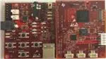
DLPDLCR2010EVM-PCB is the PCB-only version of the DLP LightCrafter Display 2010 evaluation module
(EVM). This EVM only includes the drive electronics for the DLP2010 DMD without any optical module.
This EVM can be used for integrating your choice of DLP2010 DMD based optical module using proper
flex cable for DMD interface and LED interface (please refer to the schematics for pinout and layout
information). Typically the flash memory (which stores the firmware) is part of the optical engine, and
therefore DLPDLCR2010EVM-PCB does not have the flash memory installed. If you would like to install
the flash memory, please refer the DLPC3435 datasheet (DLPS038) for flash memory requirements and
recommend flash memory.
Figure 2. DLP LightCrafter Display PCB
In addition to this document, see Section 2 for more information.
2
Applicable Documents
The following documents are applicable to the DLP LightCrafter Display 2010 EVM and are available at
www.ti.com.
• DLP2010 (0.2 WVGA) DMD data sheet (DLPS046)
• DLPC3435 controller data sheet (DLPS038)
• Software Programmer's Guide (DLPU020A)
• DLP LightCrafter Display EVM GUI Tool User's Guide (DLPU021)
For assistance, refer to the DLP and MEMS TI E2E community support forums.
DLPU027D – August 2014 – Revised March 2019
Submit Documentation Feedback
DLP® LightCrafter™ display 2010 EVM user’s guide
Copyright © 2014–2019, Texas Instruments Incorporated
3
�What is in the LightCrafter Display 2010 EVM?
3
www.ti.com
What is in the LightCrafter Display 2010 EVM?
The DLP LightCrafter Display module consists of three subsystems:
• Light engine: includes the optics, red, green, and blue LEDs, and the 854 x 480 (WVGA) DMD.
Capable of 25 lumens out-of-the-box.
• Driver board: includes the DLP chipset comprising of DLPC3435 Controller and DLPA2005 PMIC/LED
driver.
• System board: includes MSP430, ITE HDMI receiver, USB-I2C bridge and several connectors for
external inputs (for example, HDMI or USB).
CY7C65215
LED connection
Flash
Optical
Engine
DMD
connection
VLED (R/G/B)
DLPA2005
1.1V
1.8V
SYSPWR
PROJ_ON
BIAS, RST, OFS
RESETZ
SPI
SPI_0
SPI_1
Flash I/F (4)
CTRL
Sub-LVDS DATA
SPI
USB-SPI
Bridge
Push Buttons
USB
PROJ_ON
I2C
MSP430
LED_SEL(2)
DLPC3435
1.8V
1.1V
I2C
Parallel I/F
24 Bit Data
CTRL
TLV320DAC3101
Parallel I/F
24 Bit Data
CTRL
EE
PROM
IT6801
I2C
5V DV
DAC
HDMI
Audio Out
Figure 3. DLP LightCrafter Display EVM Block Diagram
4
DLP® LightCrafter™ display 2010 EVM user’s guide
DLPU027D – August 2014 – Revised March 2019
Submit Documentation Feedback
Copyright © 2014–2019, Texas Instruments Incorporated
�Light Engine
www.ti.com
4
Light Engine
The optical engine in the EVM is developed by Asia Optics and is production ready.
The light engine consists of the following components:
• 0.2-inch WVGA DMD (DLP2010)
• OSRAM red, green and blue LED – LE BA Q6WM and LCG H9RM
• This light engine interfaces with the EVM using DMD pin mapping Option 1. Please refer to the
DLPC3430 and DLPC3435 datasheet for more information about the DMD interface.
Table 1. Optical Engine Specifications
PARAMETER
MIN
Brightness
LED current
Brightness uniformity
TYP
MAX
UNIT
25
Lum
650
mA
75%
Throw ratio
1.65
Offset
100%
Focus range
5
50
inch
Image diagonal size
5
50
inch
The dimensions of the optical engine are shown in Figure 4:
Figure 4. Dimensions of Optical Engine
5
Quick-Start Procedure
This quick-start assumes default conditions as shipped.
1. Power up the DLP LightCrafter™ Display 2010 EVM by applying an external DC power supply (5-V
DC, 3.0 A) to the J12 connector.
• Note: Use an AC-DC switching power supply which accepts 50-60Hz 100-240VAC inputs, and
outputs a nominal 5 VDC at maximum 3-A output current. The PWRON (D16) and SYSPWR (D15)
LED turns on to indicate that 5-V power is applied.
DLPU027D – August 2014 – Revised March 2019
Submit Documentation Feedback
DLP® LightCrafter™ display 2010 EVM user’s guide
Copyright © 2014–2019, Texas Instruments Incorporated
5
�Circuit Description
www.ti.com
2. Move the SW_ONOFF switch to the ON position to turn the DLP LightCrafter™ Display 2010 EVM on.
When the LightCrafter™ Display 2010 EVM is turned on, the PROJ_ON LED turns on.
3. After the DLP LightCrafter™ Display 2010 EVM is turned on, the projector default is to display a DLP
LightCrafter™ Display splash image.
4. The focus of the image can be adjusted with the focus wheel on the optical engine.
Focus wheel
Figure 5. Optical Engine with Focus Wheel
5. Connect USB to the LightCrafter Display 2010 EVM and open the GUI on your Computer. If needed,
connect an HDMI source to the EVM and communicate to the EVM over the GUI software.
6. When turning off the projector, turn off the SW_ONOFF switch prior to removing power cable. Note: To
avoid potential damage to the DMD, it is recommended to turn off the projector with the SW_ONOFF
before disconnecting the power.
7. There are ten indicator LEDs on the DLP LightCrafter™ Display 2010 EVM ( Table 2):
Table 2. LEDs on the DLP LightCrafter Display 2010 EVM
D15
SYSPWR
5-V Power applied
D16
PWRON
Regulated 3V3 power on
D7
PROJ_ON
D6
RESETZ
D5
HOST_IRQ
D9
MSP2
D8
ACK
ON when Cypress CY3420 is I2C master OFF when MSP430 is I2C master
D10
REQ
ON when Cypress CY3420 requests the MSP430 to give Cypress master control
of the I2C bus
D12
GPIO1
Blinking when PC is communicating to flash over SPI
D14
GPIO0
Blinking when PC is communicating to DLPC3435 over I2C
On when Projector is turned on via SW_ONOFF
OFF when Projector is turned on vie SW_ONOFF
ON during DLPC3435 boot OFF when projector is running. Indication of
DLPC3435 boot-up completed and ready to receive commands
ON when HDMI cable plugged in and external video detected. OFF when external
video is not detected.
6
Circuit Description
6.1
Connectors, Switch and Push buttons on Main Board
Table 3. List of Installed Connectors on the Main board
INSTALLED CONNECTORS/HEADERS
6
DESCRIPTION
J12
Connector for 5-V external power supply interface
J7
Connector for USB cable
J2
Connector for Audio
J4
Connector for HDMI input
DLP® LightCrafter™ display 2010 EVM user’s guide
DLPU027D – August 2014 – Revised March 2019
Submit Documentation Feedback
Copyright © 2014–2019, Texas Instruments Incorporated
�Circuit Description
www.ti.com
Table 3. List of Installed Connectors on the Main board (continued)
INSTALLED CONNECTORS/HEADERS
DESCRIPTION
J1
MSP430 JTAG Programming interface connector
J13
Connector for the I2C interface (DevaSys box)
J6
60 pin connector for DLP LightCrafter Display board
J10
Header for 5-V DC power
J11
Header for 5-V DC power
J3
Unsupported
J5
Unsupported
Table 4. List of Installed Push Buttons and Switch on Main Board
INSTALLED SWITCHES/PUSH BUTTONS
SW1
DESCRIPTION
Projector On/OFF Switch
Source selection
1.
2.
3.
PB-UP1
PB-SEL1
Cycle through displaying 7 curtain colors
PB-DOWN1
Flip image N/S or E/W
PB_LEFT1
Cycle 9 different TPG patterns after TPG source selected
Cycle 4 different Splash screens after Splash source selected
Change of Volume when HDMI input is selected
Change LED current total 7 steps
Change of Volume when HDMI input is selected
PB_RIGHT1
6.2
Press: TPG
Press: HDMI input
Press: Splash screen
Connectors on DLP LightCrafter™ Display board
Table 5. List of Installed Connectors on the DLP LightCrafter™ Display Board
INSTALLED SWITCHES/PUSH BUTTONS
7
DESCRIPTION
J1
Connector for the DMD flex cable
J2
Connector for LED cable
J3
Connector for external temperature sensor (Requires removing R21)
J4
Connector for light sensor
J5
Future use
J6
60 pin connector for DLP LightCrafter Display board
EVM Setup
The DLP LightCrafter™ Display 2010 EVM is composed of three parts:
• Main board
• DLP LightCrafter Display board
• Engine with LED connection and Flex cable
The main board contains the connector for the power supply, the USB connector to communicate to the
DLP LightCrafter Display software, the HDMI, audio and the connector for the DLP LightCrafter Display
board. The main board also contains the switch to turn on the projector in case the DLP LightCrafter
Display board and the engine is connected. Figure 6 shows the main connectors on the main board.
DLPU027D – August 2014 – Revised March 2019
Submit Documentation Feedback
DLP® LightCrafter™ display 2010 EVM user’s guide
Copyright © 2014–2019, Texas Instruments Incorporated
7
�EVM Setup
www.ti.com
Audio interface
HDMI connector
Projector ON/OFF
switch
5 V power
connector
DLP LightCrafter
Display board
connector
USB connector
Figure 6. DLP LightCrafter Display main board
The DLP LightCrafter Display board has three main connectors: the LED connector, the Flex cable
connector, and the main board connector. To connect the main board to the DLP LightCrafter Display
board, refer to Figure 7. Note that the main board connector on the DLP LightCrafter™ Display board is
on the bottom while the LED and Flex cable connectors are on the top.
Figure 7. Connection Main Board and DLP LightCrafter Display Board
Figure 8 shows the board connections.
8
DLP® LightCrafter™ display 2010 EVM user’s guide
DLPU027D – August 2014 – Revised March 2019
Submit Documentation Feedback
Copyright © 2014–2019, Texas Instruments Incorporated
�EVM Setup
www.ti.com
LED
connector
Flex cable
connector
Figure 8. DLP LightCrafter Display
The engine requires four connections:
• two connections from the flex cable:
– one for the DMD
– one for the flash card mounted on the engine
• two connections from a small adapter board to ensure communication with the LEDs
Figure 9 shows the proper setup.
The pins of the flex cable connector are labeled with the pin numbers. Verify that the pin numbers match
when connecting the flex cable.
To ensure the LED cables are connected correctly, use the colored circles to trace each cable to the right
connection. Figure 9 shows how to verify the connection. .
DMD
DMD
connector
connec
Flashccard
Flash
connector
connec
Figure 9. LED Connection and Flex Cable Connection
Figure 10 shows the final setup of all components.
DLPU027D – August 2014 – Revised March 2019
Submit Documentation Feedback
DLP® LightCrafter™ display 2010 EVM user’s guide
Copyright © 2014–2019, Texas Instruments Incorporated
9
�EVM Setup
www.ti.com
Figure 10. DLP LightCrafter Display complete EVM
Make sure that everything is setup correctly before continuing. Verify that the flex cable is connected
correctly to the DMD and to the LightCrafter Display board.
10
DLP® LightCrafter™ display 2010 EVM user’s guide
DLPU027D – August 2014 – Revised March 2019
Submit Documentation Feedback
Copyright © 2014–2019, Texas Instruments Incorporated
�Revision History
www.ti.com
Revision History
NOTE: Page numbers for previous revisions may differ from page numbers in the current version.
Changes from C Revision (February 2019) to D Revision ............................................................................................. Page
•
Corrected pin mapping option listing from 3 to 1 in Section 4....................................................................... 5
Changes from B Revision (October 2015) to C Revision ............................................................................................... Page
•
Added pin mapping option description in Section 4
..................................................................................
5
Changes from A Revision (October 2014) to B Revision ............................................................................................... Page
•
Added DLP Lightcrafter Display 2010 PCB Overview section
......................................................................
DLPU027D – August 2014 – Revised March 2019
Submit Documentation Feedback
Copyright © 2014–2019, Texas Instruments Incorporated
Revision History
3
11
�IMPORTANT NOTICE AND DISCLAIMER
TI PROVIDES TECHNICAL AND RELIABILITY DATA (INCLUDING DATA SHEETS), DESIGN RESOURCES (INCLUDING REFERENCE
DESIGNS), APPLICATION OR OTHER DESIGN ADVICE, WEB TOOLS, SAFETY INFORMATION, AND OTHER RESOURCES “AS IS”
AND WITH ALL FAULTS, AND DISCLAIMS ALL WARRANTIES, EXPRESS AND IMPLIED, INCLUDING WITHOUT LIMITATION ANY
IMPLIED WARRANTIES OF MERCHANTABILITY, FITNESS FOR A PARTICULAR PURPOSE OR NON-INFRINGEMENT OF THIRD
PARTY INTELLECTUAL PROPERTY RIGHTS.
These resources are intended for skilled developers designing with TI products. You are solely responsible for (1) selecting the appropriate
TI products for your application, (2) designing, validating and testing your application, and (3) ensuring your application meets applicable
standards, and any other safety, security, regulatory or other requirements.
These resources are subject to change without notice. TI grants you permission to use these resources only for development of an
application that uses the TI products described in the resource. Other reproduction and display of these resources is prohibited. No license
is granted to any other TI intellectual property right or to any third party intellectual property right. TI disclaims responsibility for, and you
will fully indemnify TI and its representatives against, any claims, damages, costs, losses, and liabilities arising out of your use of these
resources.
TI’s products are provided subject to TI’s Terms of Sale or other applicable terms available either on ti.com or provided in conjunction with
such TI products. TI’s provision of these resources does not expand or otherwise alter TI’s applicable warranties or warranty disclaimers for
TI products.
TI objects to and rejects any additional or different terms you may have proposed. IMPORTANT NOTICE
Mailing Address: Texas Instruments, Post Office Box 655303, Dallas, Texas 75265
Copyright © 2022, Texas Instruments Incorporated
�