DLP® LightCrafter™ 6500 and 9000 Evaluation
Module (EVM) User's Guide
User's Guide
Literature Number: DLPU028D
October 2014 – Revised March 2019
�Contents
Preface ........................................................................................................................................ 6
1
DLP LightCrafter 6500 and 9000 Module Overview ................................................................... 9
1.1
1.2
1.3
1.4
1.5
1.6
1.7
2
Quick Start ........................................................................................................................ 23
2.1
2.2
3
Power-up the DLP LightCrafter 6500 or 9000 .......................................................................... 23
Creating A Simple Pattern Sequence ................................................................................... 24
Operating the DLP LightCrafter 6500 and 9000....................................................................... 27
3.1
3.2
3.3
3.4
3.5
3.6
3.7
3.8
3.9
3.10
3.11
2
Welcome ...................................................................................................................... 9
DLP LightCrafter 6500 and 9000 Evaluation Module (EVM) Hardware ............................................. 10
EVM Boards ................................................................................................................ 11
Other Items Needed for Operation ....................................................................................... 13
DLP LightCrafter 6500 Connections ..................................................................................... 14
1.5.1 DLP LightCrafter 6500 LED Enable and PWM Outputs...................................................... 16
1.5.2 DLP LightCrafter 6500 Trigger Input and Output Voltage Selectors ....................................... 17
DLP LightCrafter 9000 Connections ..................................................................................... 18
1.6.1 DLP LightCrafter 9000 LED Enable and PWM Outputs...................................................... 20
1.6.2 DLP LightCrafter 9000 Trigger Input and Output Voltage Selectors ....................................... 20
DLP LightCrafter 6500 and DLP LightCrafter 9000 EVM Flex Cable ............................................... 22
DLP LightCrafter 6500 and 9000 Control Software ....................................................................
PC Software.................................................................................................................
System Common Controls ................................................................................................
3.3.1 Operating Mode ...................................................................................................
3.3.2 Chipset Type .......................................................................................................
3.3.3 EVM Information ...................................................................................................
3.3.4 Status ...............................................................................................................
System Settings ............................................................................................................
Video Mode .................................................................................................................
3.5.1 Video Support ......................................................................................................
Pattern Modes ..............................................................................................................
3.6.1 Menu Bar ...........................................................................................................
3.6.2 Creating a Pattern Sequence in Pattern On-The-Fly Mode .................................................
3.6.3 Creating a Pattern Sequence in Pre-Stored Pattern Mode ..................................................
3.6.4 Reordering a Pattern Sequence using the Edit LUT Feature ...............................................
3.6.5 Creating a Pattern Sequence in Video Pattern Mode ........................................................
3.6.6 Creating a Pattern Sequence With DMD Block Load ........................................................
3.6.7 Pattern Settings....................................................................................................
Batch Files ..................................................................................................................
3.7.1 Execute Batch File ................................................................................................
3.7.2 Creating and Saving Batch Files ................................................................................
3.7.3 Loading a Batch File ..............................................................................................
3.7.4 Adding a Batch File to the Firmware............................................................................
Peripherals ..................................................................................................................
Firmware.....................................................................................................................
3.9.1 Adding or Removing Patterns from the Firmware.............................................................
Flash Device Parameters .................................................................................................
JTAG Flash Programming ................................................................................................
Contents
27
28
28
29
29
29
29
31
32
33
34
35
35
38
39
42
44
46
48
48
49
50
51
52
53
54
59
59
DLPU028D – October 2014 – Revised March 2019
Submit Documentation Feedback
Copyright © 2014–2019, Texas Instruments Incorporated
�www.ti.com
3.12
4
Connectors ........................................................................................................................ 61
4.1
4.2
4.3
4.4
4.5
4.6
4.7
4.8
4.9
5
Input Trigger Connectors ..................................................................................................
Output Trigger Connectors ................................................................................................
DLPC900 UART ............................................................................................................
DLPC900 I2C Port 0 ........................................................................................................
DLPC900 I2C Port 1 ........................................................................................................
DLPC900 I2C Port 2 ........................................................................................................
JTAG Boundary Scan......................................................................................................
GPIO and PWM ............................................................................................................
Power ........................................................................................................................
61
61
62
62
62
63
63
63
64
Power Supply Requirements ................................................................................................ 65
5.1
6
Intel (Altera) FPGA Programming ........................................................................................ 60
External Power Supply Requirements ................................................................................... 65
Safety
6.1
............................................................................................................................... 66
Caution Labels .............................................................................................................. 66
Revision D History ....................................................................................................................... 66
Revision C History ....................................................................................................................... 67
Revision B History ....................................................................................................................... 67
Revision A History ....................................................................................................................... 68
DLPU028D – October 2014 – Revised March 2019
Submit Documentation Feedback
Copyright © 2014–2019, Texas Instruments Incorporated
Contents
3
�www.ti.com
List of Figures
DLP LightCrafter 6500 Evaluation Module
2.
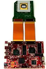
DLP LightCrafter 9000 Evaluation Module
1-1.
1-2.
1-3.
1-4.
1-5.
6
7
1-8.
1-9.
1-10.
1-11.
2-1.
2-2.
3-1.
3-2.
3-3.
3-4.
3-5.
3-6.
3-7.
3-8.
3-9.
3-10.
3-11.
3-12.
3-13.
3-14.
3-15.
3-16.
3-17.
3-18.
3-19.
3-20.
3-21.
3-22.
3-23.
4
.............................................................................. 7
.............................................................................. 8
DLP LightCrafter 6500 Hardware Components ........................................................................ 10
DLP LightCrafter 9000 Hardware Components ........................................................................ 10
DLP LightCrafter 6500 EVM Block Diagram ............................................................................ 11
DLP LightCrafter 9000 EVM Block Diagram ............................................................................ 12
DLP LightCrafter 6500 Connectors (Top View) ........................................................................ 14
Correct J14 & J15 Labels ................................................................................................. 15
Incorrect J14 & J15 Labels................................................................................................ 15
DLP LightCrafter 6500 Trigger Voltage Level Selectors .............................................................. 17
DLP LightCrafter 9000 Connectors (Top View) ........................................................................ 18
DLP LightCrafter 9000 Trigger Voltage Level Selectors .............................................................. 21
Flex Cable Diagram ........................................................................................................ 22
Pattern Mode Panel ........................................................................................................ 25
Simple Three Pattern Sequence ......................................................................................... 26
DLP LightCrafter 6500/9000 GUI ........................................................................................ 28
System Settings Panel..................................................................................................... 31
Video Mode Panel .......................................................................................................... 32
Pattern Mode Design Panel ............................................................................................... 34
Pattern Mode Menu Bar ................................................................................................... 35
Add From List ............................................................................................................... 36
Pattern Sequence .......................................................................................................... 36
Three Pattern Sequence .................................................................................................. 37
Pattern Design Example................................................................................................... 39
LUT Editor Panel ........................................................................................................... 40
Reorder Example ........................................................................................................... 41
Video Pattern Mode ........................................................................................................ 43
DMD Block Load Pattern Sequence ..................................................................................... 45
Pattern Settings Panel ..................................................................................................... 47
Batch Files Panel ........................................................................................................... 48
Batch File Example ........................................................................................................ 50
Peripherals Panel .......................................................................................................... 52
Firmware Panel ............................................................................................................. 54
Pattern LUT Definition and Configuration ............................................................................... 57
Updating the Index and Bit Position ..................................................................................... 58
Flash Device Parameters Text File ...................................................................................... 59
UM232H Module ........................................................................................................... 59
UM232H Wiring Diagram .................................................................................................. 59
1.
List of Figures
DLPU028D – October 2014 – Revised March 2019
Submit Documentation Feedback
Copyright © 2014–2019, Texas Instruments Incorporated
�www.ti.com
List of Tables
....................................................................................
3-1.
Resolution and Frame Rate Support
4-1.
Trigger Input Connector Pins ............................................................................................. 61
4-2.
Trigger Output Connector Pins ........................................................................................... 61
4-3.
UART Connector Pins ..................................................................................................... 62
4-4.
I2C Port 0 Connector Pins ................................................................................................. 62
4-5.
I2C Port 1 Connector Pins ................................................................................................. 62
4-6.
I2C Port 2 Connector Pins ................................................................................................. 63
4-7.
JTAG Boundary Scan Connector Pins .................................................................................. 63
4-8.
GPIO and PWM Connector Pins ......................................................................................... 64
4-9.
Power Connector Pins ..................................................................................................... 64
DLPU028D – October 2014 – Revised March 2019
Submit Documentation Feedback
Copyright © 2014–2019, Texas Instruments Incorporated
List of Tables
33
5
�Preface
DLPU028D – October 2014 – Revised March 2019
Read This First
The DLP® LightCrafter™ 6500 and 9000 evaluation modules (EVMs) offer a reference design to enable
faster development cycles for users of the DLP9000, DLP6500 and DLPC900 chips. This platform targets
applications needing intelligent pattern management along with high resolution display.
Trademarks
LightCrafter is a trademark of Texas Instruments.
DLP is a registered trademark of Texas Instruments.
DisplayPort is a trademark of DisplayPort.
HDMI is a registered trademark of HDMI.
About This Guide
This guide explains the hardware and software features of the DLP LightCrafter 6500 and 9000 systems.
The EVM architecture and connectors will be described along with a quick start guide on how to operate
the DLP LightCrafter 6500 and 9000 EVMs using a GUI. Specific DLP chip details and operation can be
found in related component documentation.
NOTE: Power supply, optics, illumination source, and cables are sold separately.
6
Read This First
DLPU028D – October 2014 – Revised March 2019
Submit Documentation Feedback
Copyright © 2014–2019, Texas Instruments Incorporated
�About This Guide
www.ti.com
Figure 1. DLP LightCrafter 6500 Evaluation Module
DLPU028D – October 2014 – Revised March 2019
Submit Documentation Feedback
Copyright © 2014–2019, Texas Instruments Incorporated
Read This First
7
�Related Documentation from Texas Instruments
www.ti.com
Figure 2. DLP LightCrafter 9000 Evaluation Module
Related Documentation from Texas Instruments
DLPC900 Data Sheet: DLPC900 Digital Controller for Advanced Light Control, DLPS037
DLP9000FLS Data Sheet: DLP9000 Family of 0.9 WQXGA Type A DMDs, DLPS036
DLP6500FLQ Data Sheet: DLP6500 0.65 1080p MVSP Type A DMD, DLPS040
DLP6500FYE Data Sheet: DLP6500 0.65 1080p MVSP S600 DMD, DLPS053
User's Guide: DLPC900 Programmer's Guide, DLPU018
If You Need Assistance
Refer to the TI E2E DLP products forum.
8
Read This First
DLPU028D – October 2014 – Revised March 2019
Submit Documentation Feedback
Copyright © 2014–2019, Texas Instruments Incorporated
�Chapter 1
DLPU028D – October 2014 – Revised March 2019
DLP LightCrafter 6500 and 9000 Module Overview
1.1
Welcome
The DLP LightCrafter 6500 and 9000 EVMs allow easy evaluation of TI’s DLP6500, DLP9000 and
DLPC900 chips. This platform brings together high resolution display and advanced pattern control
making it well suited for:
• Structured light applications
– Factory automation and 3D machine vision
– In-line automated optical 3D inspection
– Robotic 3D vision
– Offline 3D metrology
– 3D scanners
– 3D identification and biometrics
• 3D printing and additive manufacturing
• Medical and life sciences
• High speed imaging and display
DLPU028D – October 2014 – Revised March 2019
Submit Documentation Feedback
DLP LightCrafter 6500 and 9000 Module Overview
Copyright © 2014–2019, Texas Instruments Incorporated
9
�DLP LightCrafter 6500 and 9000 Evaluation Module (EVM) Hardware
1.2
www.ti.com
DLP LightCrafter 6500 and 9000 Evaluation Module (EVM) Hardware
The DLP LightCrafter 6500 and 9000 module consist of two subsystems:
• DLPC900 Board – Includes the DLPC900, digital receiver, flash, power management circuits, and
supporting digital logic.
• DMD Board – Includes the DLP9000 or the DLP6500 digital micromirror device (DMD) and power
management circuits.
Figure 1-1 and Figure 1-2 show the major hardware components for both EVMs.
DLP9000 DMD Board
DLP6500 DMD Board
DLP9000
WQXGA
DLP6500
1080p
Two
Flex
Cables
Flex
Cable
Master
DLPC900
DLPC900
H
o
s
t
C
o
n
n
e
c
t
o
r
Flash
Flash
LED Enable
and PWM
Control
H
o
s
t
Triggers
C
o
n
n
e
c
t
o
r
I2C
Power
Management
USB
HDMI
DisplayPort
DLPC900
Board
Figure 1-1. DLP LightCrafter 6500 Hardware
Components
10
Slave
DLPC900
DLP LightCrafter 6500 and 9000 Module Overview
Flash
LED
Enable and PWM
Control
Triggers
I2C
FPGA
Power
Management
USB
HDMI
DisplayPort
Dual
DLPC900
Board
Figure 1-2. DLP LightCrafter 9000 Hardware
Components
DLPU028D – October 2014 – Revised March 2019
Submit Documentation Feedback
Copyright © 2014–2019, Texas Instruments Incorporated
�EVM Boards
www.ti.com
1.3
EVM Boards
The DLP LightCrafter 6500 and 9000 EVMs contain the electronics to drive the DLP6500 and the
DLP9000 DMDs. The EVMs offer several interface options for USB, I2C, trigger inputs and outputs, video
input through HDMI and Display Port connectors. Figure 1-3 shows the EVM block diagram of the DLP
LightCrafter 6500 and Figure 1-4 shows the EVM block diagram of the DLP LightCrafter 9000.
Flash
M29DW128G70
MOSC
X2
Boot Mode (J11)
DMD Connector
(J16)
CSZ_0
CSZ_1
CSZ_2
FLEX
LED Connector
(J23)
LED Enable
LED PWM
MOSC_P
DLP6500
Trigger In
Trigger In (J20)
BOOTHOLDZ
Trigger
Voltage Selectors
(J19, J21, J22, J25)
USB (J7)
USB_N/USB_P
I2C0 (J13)
SCL0/SDA0
I2C2 (J15)
SCL2/SDA2
I2C1 (J14)
SCL1/SDA1
UART0
UART (J6)
HDMI EDID (J3)
EDID PROM
OCLKA
OCLKA (J5)
DP EDID (J4)
EDID PROM
FAULT_STATUS
D5
HEARTBEAT
D6
DP (J2)
IT6535
HDMI (J1)
Trigger Out
DLPC900
RGB
SYNCS
PCLK
JTAG BS (J10)
12VDC
J17
D8
POSENSE
1.15V
TPS54320RHLR
GPIO/PWM
GPIO/PWM (J12)
D9
JTAG ICE (J8)
12VDC
(J18)
Trigger Out (J24)
1.8V
TPS54320RHLR
SW1
Reset Hold (J9)
PWRGOOD
12VDC
12V Supervisor
TL7712ACDR
Logic Gate
SN74LV21APWR
1.8V LDO
TPS76618D
3.3V
TPS54620RGYR
1.8V LDO
TLV117118DCY
Figure 1-3. DLP LightCrafter 6500 EVM Block Diagram
DLPU028D – October 2014 – Revised March 2019
Submit Documentation Feedback
DLP LightCrafter 6500 and 9000 Module Overview
Copyright © 2014–2019, Texas Instruments Incorporated
11
�EVM Boards
www.ti.com
DMD Connector
(J18)
CSZ_0
CSZ_1
CSZ_2
Flash
M29DW128G70
MOSC
X2
Trigger In
Trigger In (J23)
BOOTHOLDZ
Trigger
Voltage Selectors
(J22, J24, J25, J28)
JTAG ICE (J9)
Trigger Out
JTAG BS (J11)
DLPC900
Trigger Out (J27)
GPIO/PWM
GPIO/PWM (J13)
USB (J8)
USB_N/USB_P
I2C0 (J14)
SCL0/SDA0
I2C2 (J16)
SCL2/SDA2
I2C1 (J15)
SCL1/SDA1
FAULT_STATUS
D6
HDMI EDID (J3)
EDID PROM
HEARTBEAT
D7
DP EDID (J4)
EDID PROM
Master
FPGA
RGB
SYNCS
PCLK
FPGA (J5)
Flash
M29DW128G70
12VDC
J20
UART (J7)
OCLKA
OCLKA (J6)
DLPC900
Slave
12V Supervisor
TL7712ACDR
12VDC
3V VCCIO
TPS62170DSGT
UART0
MOSC_P
POSENSE
1.8V
TPS54320RHLR
FLEX
UART (J17)
S_RESET
HEARTBEAT
1.15V
TPS54620RGYR
Reset Hold (J10)
PWRGOOD
Slave Reset (J29)
D9
FAULT_STATUS
D11
SW1
DMD Connector
(J19)
BOOTHOLDZ
CSZ_0
CSZ_1
CSZ_2
D8
12VDC
(J21)
I2C
D5
JTAG
GPIO
HDMI (J1)
SSP
SYNC
IT6535
UART0
D12
RGB
SYNCS
PCLK
DP (J2)
DLP9000
LED Connector
(J26)
LED Enable
LED PWM
MOSC_P
Boot Mode (J12)
FLEX
Logic Gate
2.5V LDO
TPS73125DBV
SN74LV21APWR
1.8V LDO
TPS76618D
3.3V
TPS54620RGYR
1.8V LDO
TLV117118DCY
Figure 1-4. DLP LightCrafter 9000 EVM Block Diagram
The DLP LightCrafter 6500 major components are:
• DLP6500 0.65-inch 1080p DMD
• DLPC900 Controller
• 48-MB parallel FLASH contains DLPC900 firmware and pattern images
• Power regulators
• IT6535 digital receiver for HDMI and Display Port Video Input
12
DLP LightCrafter 6500 and 9000 Module Overview
DLPU028D – October 2014 – Revised March 2019
Submit Documentation Feedback
Copyright © 2014–2019, Texas Instruments Incorporated
�Other Items Needed for Operation
www.ti.com
The DLP LightCrafter 9000 EVM major components are:
• DLP9000 0.9-inch WQXGA DMD
• FPGA
• 2x DLPC900 Controllers
• 2x 48 MB parallel FLASH contains DLPC900 firmware and pattern images
• Power regulators
• IT6535 digital receiver for HDMI and Display Port Video Input
1.4
Other Items Needed for Operation
The DLP LightCrafter 6500 and 9000 EVMs are flexible, ready-to-use evaluation modules (EVM).
However, the DLP LightCrafter 6500 and 9000 EVMs do not ship with optics, illumination source, cables,
power supplies, or additional hardware components. The following items may be needed for operation:
• Power supply - see Section 5.1 External Power Supply Requirements for details
• USB cable: A to B USB cable
• Display cable - HDMI® or DisplayPort™ cable (if using video input)
• Optics
• An Illumination module or source
DLPU028D – October 2014 – Revised March 2019
Submit Documentation Feedback
DLP LightCrafter 6500 and 9000 Module Overview
Copyright © 2014–2019, Texas Instruments Incorporated
13
�DLP LightCrafter 6500 Connections
1.5
www.ti.com
DLP LightCrafter 6500 Connections
Figure 1-5 depicts the switches and connectors with their respective locations. Note: Power supply (and
cable), USB cable, and display cable are NOT included with the module.
J18
J17
J2
D9
J1
J7
J4
D8
J3
J21
J19
J8
J20
J10
J24
J13
J14
J15
J25
J25
J11
D6
SW1
J12
D5
J9
J16
J6
J5
J23
Figure 1-5. DLP LightCrafter 6500 Connectors (Top View)
•
•
•
•
•
•
•
•
•
14
SW1 – Reset switch. When pressed, resets the controller.
J1 – HDMI Connector. Default primary video input after power is applied to the EVM.
J2 – DisplayPort Connector. Secondary video input.
J3 – HDMI EDID jumper. When jumper is installed, the EDID prom can be updated.
J4 – DisplayPort EDID jumper. When jumper is installed, the EDID prom can be updated.
J5 – OCLKA connector. Configurable output clock A.
– Bits per second: 115200
– Data bits: 8
– Parity: None
– Flow Control: None
– Pin 1 = 3.3 V
– Pin 2 = TX out
– Pin 6 = Ground
J7 – USB connector. USB interface to PC or host for communications with the DLPC900.
J8 – JTAG ICE. Used for debugging code. Requires the ARM RVI ICE debugger.
J9 – Controller RESET jumper. When jumper is installed, the controller is held in RESET.
DLP LightCrafter 6500 and 9000 Module Overview
DLPU028D – October 2014 – Revised March 2019
Submit Documentation Feedback
Copyright © 2014–2019, Texas Instruments Incorporated
�DLP LightCrafter 6500 Connections
www.ti.com
•
•
•
•
•
J10 – JTAG Boundary Scan connector. Used for programming the boot image into the flash memory
when flash memory is blank or corrupted.
J11 – HOLD Boot mode jumper. When the jumper is installed, it will force the controller to remain in
boot mode when power is applied.
J13 – I2C Port 0 connector. Connector on bottom side of EVM. Dedicated I2C interface port for host
communications.
– Pin 1 is SCL
– Pin 2 is SDA
– Pin 3 is 3.3 V
– Pin 4 is GND
J14 – I2C Port 1 connector (see note). Connector on bottom side of EVM.
– Pin 1 is SCL
– Pin 2 is SDA
– Pin 3 is 3.3 V
– Pin 4 is GND
J15 – I2C Port 2 connector (see note). Connector on bottom side of EVM.
– Pin 1 is SCL
– Pin 2 is SDA
– Pin 3 is 3.3 V
– Pin 4 is GND
NOTE: On one board lot, the silk screen labels J14 and J15 are swapped. Labels for I2C_1 and
I2C_2 on the boards are correct. I2C_1 is J14 and I2C_2 is J15.
Figure 6. Correct J14 & J15 Labels
•
•
•
•
•
•
•
Figure 7. Incorrect J14 & J15 Labels
J16 – DMD flex connector. DMD flex connector for DMD data and control.
J17 – 12-V power connector. 12-V DC input. see Section 5.1
– Pin 1 is 12-V DC.
– Pin 2 and 3 are ground.
J18 – 12-V power connector. 12-V DC input.
– Pins 1, 2, and 3 are ground.
– Pins 4, 5, and 6 are 12-V DC.
J19 –Trigger 1 input voltage level selectors. See Figure 1-8.
– Jump across pins 1 to 2 for 3.3 V
– Jump across pins 2 to 3 for 1.8 V
J20 – Trigger input connector. Trigger input 1 and 2 for triggering the controller with external devices.
J21 –Trigger 2 input voltage level selectors. See Figure 1-8.
– Jump across pins 1 to 2 for 3.3 V
– Jump across pins 2 to 3 for 1.8 V
J22 –Trigger output voltage level selectors. See Figure 1-8.
DLPU028D – October 2014 – Revised March 2019
Submit Documentation Feedback
DLP LightCrafter 6500 and 9000 Module Overview
Copyright © 2014–2019, Texas Instruments Incorporated
15
�DLP LightCrafter 6500 Connections
•
•
•
•
•
•
•
www.ti.com
– Jump across pins 1 to 2 for 3.3 V
– Jump across pins 2 to 3 for 1.8 V
J23 – LED Enable and PWM connector.
– Pin 1, 2, and 3 are 12 V.
– Pin 4 is NC.
– Pin 5 is Red LED Enable output.
– Pin 6 is Green LED Enable output.
– Pin 7 is Blue LED Enable output.
– Pin 8 is RED PWM output.
– Pin 9 is Green PWM output.
– Pin 10 is Blue PWM output.
– Pin 11, 12, 13, and 14 are ground.
J24 – Trigger output connector. Trigger outputs 1 and 2 for triggering external devices.
J25 –Trigger output voltage level selectors. See Figure 1-8.
– Jump across pins 1 to 2 for 3.3 V
– Jump across pins 2 to 3 for 1.8 V
D5 – Red fault status LED. When lit indicates a fault has occurred in the controller
D6 – Green Heartbeat LED. When toggling indicates controller is operating.
D8 – 12-V Power LED. When lit indicates external 12-V supply is on.
D9 – PWRGOOD LED. When lit indicates power is normal.
1.5.1 DLP LightCrafter 6500 LED Enable and PWM Outputs
The LED enables on J23 are low-current 3.3-V outputs and should not be used to drive LEDs directly. The
enables should be used as a control to enable a regulator that provides the necessary current to the
LEDs. The PWM outputs are also 3.3-V outputs and used for controlling the current to the LEDs, which
controls the brightness.
NOTE: The 12-V DC output on J23 should not be used to power the LED drive circuitry as it does
not provide the necessary current when all three LED enables are simultaneous turned on.
Doing so can cause a drop in the 12-V supply to the EVM regulator circuitry and reset the
controller.
16
DLP LightCrafter 6500 and 9000 Module Overview
DLPU028D – October 2014 – Revised March 2019
Submit Documentation Feedback
Copyright © 2014–2019, Texas Instruments Incorporated
�DLP LightCrafter 6500 Connections
www.ti.com
1.5.2 DLP LightCrafter 6500 Trigger Input and Output Voltage Selectors
The trigger inputs on J20 are inputs from external devices to control the pattern sequence. While trigger
input 2 is high, trigger input 1 will advance the pattern sequence to the next pattern in the sequence on
every pulse.
The trigger outputs on J24 are outputs to control external devices. While trigger output 1 going high
indicates the start of the exposure time of the pattern (and going low indicates the stop), trigger output 2
marks the beginning of each pattern start with a 20 µs pulses. Trigger output 1 can be used for triggering
a camera and capturing the patterns as they are displayed on some object. A computer can then use
trigger output 2 to keep track of each pattern. The captured images can then be reassembled to produce,
for example, a 3D point cloud.
Both input and output triggers have voltage level selectors. Use J19, J21, J22, and J25 to select the
voltage as shown in Figure 1-8. If no voltage is selected, then the onboard logic will not be functional and
any outgoing or incoming signals will not available.
J21
Pin 3
Pin 2
Pin 1
J19
Pin 3
Pin 2
Pin 1
J25
Pin 3
Pin 2
Pin 1
J22
Pin 3
Pin 2
Pin 1
Figure 1-8. DLP LightCrafter 6500 Trigger Voltage Level Selectors
DLPU028D – October 2014 – Revised March 2019
Submit Documentation Feedback
DLP LightCrafter 6500 and 9000 Module Overview
Copyright © 2014–2019, Texas Instruments Incorporated
17
�DLP LightCrafter 9000 Connections
1.6
www.ti.com
DLP LightCrafter 9000 Connections
Figure 1-9 depicts the switches and connectors with their respective locations. Note: Power supply (and
cable), USB cable, and display cable are NOT included with the module.
J3
J4
D12
SW1
J10
J5
D5
J29
J12
D11
J20
J1
J21
J22
J24
J2
J23
J16
J15
J14
J6
J11
J28
J27
J9
J25
J8
J17
J19
D8
D9
J26
J18
D7
D6
J13
J7
Figure 1-9. DLP LightCrafter 9000 Connectors (Top View)
•
•
•
•
•
•
•
•
18
SW1 – Reset switch. When pressed resets the controller.
J1 – HDMI Connector. Default primary video input after power is applied to the EVM.
J2 – DisplayPort Connector. Secondary video input.
J3 – HDMI EDID jumper. When jumper is installed, the EDID prom can be updated.
J4 – DisplayPort EDID jumper. When jumper is installed, the EDID prom can be updated.
J5 – Intel (Altera) FPGA programming connector. Use Intel (Altera) tools to program the FPGA.
J6 – OCLKA connector. Configurable output clock A.
– Pint 1 is clock output.
– Pin 2 is ground.
J7 – Master DLPC900 UART header. Supports only output debug messages to terminal with the below
settings. The outputs are 3.3-V TTL level and require an external transceiver to convert to RS232.
– Bits per second: 115200
– Data bits: 8
– Parity: None
– Flow Control: None
– Pin 1 = 3.3 V
– Pin 2 = TX out
DLP LightCrafter 6500 and 9000 Module Overview
DLPU028D – October 2014 – Revised March 2019
Submit Documentation Feedback
Copyright © 2014–2019, Texas Instruments Incorporated
�DLP LightCrafter 9000 Connections
www.ti.com
•
•
•
•
•
•
•
•
•
•
•
•
•
•
•
•
– Pin 6 = Ground
J8 – USB connector. USB interface to host for communications with the DLPC900.
J9 – JTAG ICE. Used for debugging code. Requires the ARM RVI ICE debugger.
J10 – Controller RESET jumper. When jumper is installed, the controller is held in RESET.
J11 – JTAG Boundary Scan connector. Used for programming the boot image into the flash memory
when flash memory is blank or corrupted.
J12 – HOLD Boot mode jumper. When jumper is installed will force the controller to remain in boot
mode when power is applied.
J13 – GPIO input/output connector.
J14 – I2C Port 0 connector. Connector on bottom side of EVM. Dedicated I2C interface port for host
communications.
– Pin 1 is SCL
– Pin 2 is SDA
– Pin 3 is 3.3 V
– Pin 4 is GND
J15 – I2C Port 1 connector. Connector on bottom side of EVM.
– Pin 1 is SCL
– Pin 2 is SDA
– Pin 3 is 3.3 V
– Pin 4 is GND
J16 – I2C Port 2 connector. Connector on bottom side of EVM.
– Pin 1 is SCL
– Pin 2 is SDA
– Pin 3 is 3.3 V
– Pin 4 is GND
J17 – Slave DLPC900 UART header. Supports only output debug messages to terminal. The outputs
are 3.3-V TTL level and require an external transceiver to convert to RS232.
J17 – Slave DLPC900 UART header. Supports only output debug messages to terminal. The outputs
are 3.3-V TTL level and require an external transceiver to convert to RS232.
– Bits per second: 115200
– Data bits: 8
– Parity: None
– Flow Control: None
– Pin 1 = 3.3 V
– Pin 2 = TX out
– Pin 6 = Ground
J18 – Master DLPC900 DMD flex connector. DMD flex connector for DMD data and control.
J19 – Slave DLPC900 DMD flex connector. DMD flex connector for DMD data and control.
J20 – 12-V power connector. 12-V DC input. see Section 5.1
– Pin 1 is 12-V DC.
– Pin 2 and 3 are ground.
J21 – 12-V power connector. 12-V DC input.
– Pins 1, 2, and 3 are ground.
– Pins 4, 5, and 6 are 12-V DC.
J22 –Trigger Input 1 voltage level selectors. See Section 1.7.
– Jump across pins 1 to 2 for 3.3 V
– Jump across pins 2 to 3 for 1.8 V
DLPU028D – October 2014 – Revised March 2019
Submit Documentation Feedback
DLP LightCrafter 6500 and 9000 Module Overview
Copyright © 2014–2019, Texas Instruments Incorporated
19
�DLP LightCrafter 9000 Connections
•
•
•
•
•
•
•
•
•
•
•
•
•
•
www.ti.com
J23 – Trigger input connector. Trigger input 1 and 2 for triggering the DLPC900 with external devices.
J24 –Trigger Input 2 voltage level selectors. See Section 1.7.
– Jump across pins 1 to 2 for 3.3 V
– Jump across pins 2 to 3 for 1.8 V
J25 –Trigger Output 1 voltage level selectors. See Section 1.7.
– Jump across pins 1 to 2 for 3.3 V
– Jump across pins 2 to 3 for 1.8 V
J26 – LED Enable and PWM connector.
– Pins 1, 2, and 3 are 12 V.
– Pin 5 is Red LED Enable output.
– Pin 6 is Green LED Enable output.
– Pin 7 is Blue LED Enable output.
– Pin 8 is RED PWM output.
– Pin 9 is Green PWM output.
– Pin 10 is Blue PWM output.
– Pins 11, 12, 13, and 14 are ground.
J27 – Trigger output connector. Trigger outputs 1 and 2 for triggering external devices.
J28 –Trigger Output 2 voltage level selectors. See Section 1.7.
– Jump across pins 1 to 2 for 3.3 V
– Jump across pins 2 to 3 for 1.8 V
J29 – Slave DLPC900 hold reset. When jumper is installed, the controller is held in RESET.
D5 – FPGA Init-Done. When lit indicates the FPGA configured without errors after power is applied.
D6 – Master DLPC900 Red fault status LED. When lit indicates a fault has occurred in the controller.
D7 – Master DLPC900 Green Heartbeat LED. When toggling indicates controller is operating.
D8 – Slave DLPC900 Red fault status LED. When lit indicates a fault has occurred in the controller.
D9 – Slave DLPC900 Green Heartbeat LED. When toggling indicates controller is operating.
D11 – 12-V Power LED. When lit indicates external 12-V supply is on.
D12 – PWRGOOD LED. When lit indicates power is normal.
1.6.1 DLP LightCrafter 9000 LED Enable and PWM Outputs
The LED enables on J26 are low-current 3.3-V outputs and should not be used to drive LEDs directly. The
enables should be used as a control to enable a regulator that provides the necessary current to the
LEDs. The PWM outputs are also 3.3-V outputs and used for controlling the current to the LEDs, which
controls the brightness.
NOTE: The 12-V DC output on J26 should not be used to power the LED drive circuitry as it does
not provide the necessary current when all three LED enables are simultaneous turned on.
Doing so can cause a drop in the 12-V supply to the EVM regulator circuitry and reset the
controller.
1.6.2 DLP LightCrafter 9000 Trigger Input and Output Voltage Selectors
The trigger inputs on J23 are inputs from external devices to control the pattern sequence. While trigger
input 2 is high, trigger input 1 will advance the pattern sequence to the next pattern in the sequence on
every pulse.
The trigger outputs on J27 are outputs to control external devices. While trigger output 1 frames the
exposure time of the pattern, trigger output 2 pulses to mark the beginning of each pattern.
20
DLP LightCrafter 6500 and 9000 Module Overview
DLPU028D – October 2014 – Revised March 2019
Submit Documentation Feedback
Copyright © 2014–2019, Texas Instruments Incorporated
�DLP LightCrafter 9000 Connections
www.ti.com
Both input and output triggers have voltage level selectors. Use J22, J24, J25, and J28 to select the
voltage as shown in Section 1.7. If no voltage is selected, then the onboard logic will not be functional and
any outgoing or incoming signals will not be available.
J24
Pin 3
Pin 2
Pin 1
J22
Pin 3
Pin 2
Pin 1
J28
Pin 3
Pin 2
Pin 1
J25
Pin 3
Pin 2
Pin 1
Figure 1-10. DLP LightCrafter 9000 Trigger Voltage Level Selectors
DLPU028D – October 2014 – Revised March 2019
Submit Documentation Feedback
DLP LightCrafter 6500 and 9000 Module Overview
Copyright © 2014–2019, Texas Instruments Incorporated
21
�DLP LightCrafter 6500 and DLP LightCrafter 9000 EVM Flex Cable
1.7
www.ti.com
DLP LightCrafter 6500 and DLP LightCrafter 9000 EVM Flex Cable
Electrical malfunctions can occur by stressing the flex cable(s) connecting the DMD circuit board to the
DLPC900 controller circuit board. Stressing the flex cable can be caused by:
• Bending the cable outside the area identified in Figure 1-11 (within 20.3 mm of connector plate
centers).
• Repeatedly bending the flex cable(s) where the bend radius is less than 25.4 mm.
• A single bending of the flex cable(s) where the bend radius is less than 6.35 mm.
Figure 1-11. Flex Cable Diagram
NOTE: The minimum bend radius for forming flex cable (flexible) circuit is 6.35 mm
Use caution when bending the flex cable to not exceed bending guidelines explained above.
22
DLP LightCrafter 6500 and 9000 Module Overview
DLPU028D – October 2014 – Revised March 2019
Submit Documentation Feedback
Copyright © 2014–2019, Texas Instruments Incorporated
�Chapter 2
DLPU028D – October 2014 – Revised March 2019
Quick Start
This chapter offers a quick start guide to power-up the EVM, run the GUI control software, and create a
simple three pattern sequence.
2.1
Power-up the DLP LightCrafter 6500 or 9000
The DLP LightCrafter 6500 and 9000 are ready to use, out of the box. Steps 1 through 6 show how to
power, display an image, and connect the EVM to a PC.
1. Connect a 12-V DC power supply to the power supply connector J17 in Figure 1-5 or J20 in Figure 1-9.
2. LEDs — D8 and D9 on the DLP LightCrafter 6500 and D5, D11, and D12 on the DLP LightCrafter
9000 — light up green to indicate configuration and power is normal.
3. LEDs — D6 on the DLP LightCrafter 6500 and D7 and D9 on the DLP LightCrafter 9000 — toggle on
and off, indicating DLPC900 is operating normally.
4. After 5 seconds, the DLPC900 displays a continuous pattern sequence.
5. Connect a USB cable from a PC to connector J7 on the DLP LightCrafter 6500, as seen in Figure 1-5
or J8 on the DLP LightCrafter 9000, as seen in Figure 1-9. The first time the cable is connected on a
PC, the DLP LightCrafter 6500 and 9000 enumerates as a USB composite device with humaninterface device (HID) class. No drivers are required since these are natively handled by all operating
systems.
6. The DLP LightCrafter 6500 and 9000 EVMs can be controlled with the free GUI software version
available for download from DLPLCR6500EVM or DLPLCR9000EVM.
NOTE: Be sure to install DLP LightCrafter 6500 or 9000 GUI software version 2.0 or newer,
operating the DLP LightCrafter 6500 or 9000 EVM with GUI version 1.1 (or version 1.0) will
render the EVM inoperable.
NOTE: The DLPC900 does not have a dedicated INIT_DONE signal output to indicate that it has
completed its power-up initialization and is ready to accept commands. The user may
configure one of the nine GPIOs available as an INIT_DONE signal output simply by adding
the GPIO configuration into a default batch file that is executed at power-up. A 10-kΩ pulldown resistor must be connected to the GPIO that will be used.
The following is an example of adding the configuration for GPIO_08 to a batch file, where
GPIO_08 is configured as an output and the signal is set high. When this command is added
to the top of the batch file, the GPIO output will go high in approximately 800 ms from the
time POSENSE goes high.
GPIO_CONFIG: 0x8 0x3
DLPU028D – October 2014 – Revised March 2019
Submit Documentation Feedback
Copyright © 2014–2019, Texas Instruments Incorporated
Quick Start
23
�Creating A Simple Pattern Sequence
2.2
www.ti.com
Creating A Simple Pattern Sequence
Before creating a pattern sequence, make sure to follow the steps in Section 2.1. Download and execute
the latest DLPC900REF-SW Windows-Installer, and then start the DLP LightCrafter 6500 & 9000 GUI
application. The GUI will detect the EVM, and the Connected radio-button will light up Green indicating the
connection was successful. The GUI software includes sample images for both the DLP LightCrafter 6500
and 9000 that will be used in the examples in this guide. If the sample image files have not been unzipped
during the installation process, then within the GUI install directory, unzip the image files to gain access to
all the sample images. All images are 1-bit binary patterns and have the native resolution of 1920x1080 or
2560x1600 for the DLP LightCrafter 6500 and 9000, respectively.
Follow these steps to create a pattern sequence. See Figure 3-5 to identify the buttons on the Menu bar.
1. Select Pattern On-The-Fly Mode from the Operating Mode group box, and click the Pattern Design
button so that the panel is displayed as shown in Figure 2-1.
2. Click the Add Pattern button (with the plus sign) in the Menu bar and browse for any three bitmap
images from the sample of images. Be sure to select them from the correct image folder for the EVM
that is being used. All three images can be selected at the same time within the open file dialog
window, but may not appear in the same order in the GUI as in the dialog window.
3. Select the first pattern within the Pattern Design panel and choose a bit depth of 1. Set exposure to
100000 µs, dark time to 50000 µs, and select Red for the color.
24
Quick Start
DLPU028D – October 2014 – Revised March 2019
Submit Documentation Feedback
Copyright © 2014–2019, Texas Instruments Incorporated
�Creating A Simple Pattern Sequence
www.ti.com
4. Select the second pattern and choose a bit depth of 1. Set exposure to 150000 µs, dark time to 75000
µs, and select Green for the color.
5. Select the third pattern and choose a bit depth of 1. Set exposure to 200000 µs, dark time to 100000
µs, and select Blue for the color. Figure 2-2 shows the pattern sequence.
6. Select the Repeat radio-button to continuously repeat the pattern sequence.
7. Click the Update LUT button to upload the pattern sequence definition including the three pattern
images to the EVM.
8. Click the Start button to run the pattern sequence.
9. Click the Stop button to stop the pattern sequence.
Figure 2-1. Pattern Mode Panel
DLPU028D – October 2014 – Revised March 2019
Submit Documentation Feedback
Copyright © 2014–2019, Texas Instruments Incorporated
Quick Start
25
�Creating A Simple Pattern Sequence
www.ti.com
Figure 2-2. Simple Three Pattern Sequence
26
Quick Start
DLPU028D – October 2014 – Revised March 2019
Submit Documentation Feedback
Copyright © 2014–2019, Texas Instruments Incorporated
�Chapter 3
DLPU028D – October 2014 – Revised March 2019
Operating the DLP LightCrafter 6500 and 9000
This chapter introduces the Windows software provided with the DLP LightCrafter 6500 and 9000.
3.1
DLP LightCrafter 6500 and 9000 Control Software
The DLPC900REF-SW bundle includes a QT-based GUI application to control the modules through the
USB interface. QT is a cross-platform application and user-interface framework with open source and
commercial licenses available. To install the QT based GUI download and execute the latest
DLPC900REF-SW Windows-Installer, and then start the DLP LightCrafter 6500 & 9000 GUI application.
The DLP LightCrafter 6500 and 9000 support two main modes of operation:
• Video Mode display images from:
– HDMI and DisplayPort inputs.
– 24-bit RGB bitmaps stored in flash memory.
– Internal test pattern generator with nine selectable patterns.
– Solid Curtain with selectable colors.
• Pattern Sequence mode displays images from:
– 1-, 2-, 3-, 4-, 5-, 6-, 7-, and 8-bit bitmap images pre-stored in Flash memory.
– 1-, 2-, 3-, 4-, 5-, 6-, 7-, and 8-bit bitmap images streamed through the DLPC900 24-bit RGB
interface.
– 1-, 2-, 3-, 4-, 5-, 6-, 7-, and 8-bit bitmap images dynamically loaded into internal memory via USB or
I2C interfaces.
DLPU028D – October 2014 – Revised March 2019
Submit Documentation Feedback
Operating the DLP LightCrafter 6500 and 9000
Copyright © 2014–2019, Texas Instruments Incorporated
27
�PC Software
3.2
www.ti.com
PC Software
Upon execution of the DLP LightCrafter 6500 & 9000 GUI application, the panel shown in Figure 3-1 is
displayed. The GUI panel contains the following three sections:
• System common controls and status on the left.
• System feature controls buttons on the top.
• Feature control panels in the center.
In any of the GUI sections, clicking a Get button reads the current settings of that particular subsection.
Clicking the Set button programs the settings into the respective subsection. Please note that some
commands may require additional steps before the GUI display is updated.
Figure 3-1. DLP LightCrafter 6500/9000 GUI
3.3
System Common Controls
The DLP LightCrafter 6500 & 9000 GUI communicates with the DLPC900 using USB 1.1. The DLPC900
enumerates as a USB device with HID Support. The PC polls all the HID peripherals and, once the PC
detects the DLPC900, the Connected radio-button changes to green. If the USB cable is disconnected,
the Connected radio-button changes to red. Once the Connected radio-button shows green, the firmware
Version and the Tag name are displayed.
The Virtual Connection option is useful when there is no connection to the EVM. When the Virtual
Connection is checked, all commands continue to operate as if there was a connection to the EVM except
for firmware uploads and updating the Look Up Table (LUT).
28
Operating the DLP LightCrafter 6500 and 9000
DLPU028D – October 2014 – Revised March 2019
Submit Documentation Feedback
Copyright © 2014–2019, Texas Instruments Incorporated
�System Common Controls
www.ti.com
3.3.1 Operating Mode
Within the System Controls group box, the GUI will update the state of the EVM to indicate it is in Normal
Operation or Standby Mode. The user may command the EVM into Standby Mode if the EVM will not be
used or the Normal Operation can be selected to command the EVM to wake up. The user may click the
Reset button to command the EVM to perform a software reset.
The EVM can be commanded to enter one of the four operating modes. Within the Operating Mode group
box there are four choices:
1. Video Mode – This mode is primarily used for display applications, and is not recommended for
applications which require pixel and timing accuracy. In this mode, the user can choose from the four
following video modes:
• Parallel RGB interface
• Internal test pattern generator with nine test patterns options
• Pattern image display from flash memory
• Solid Curtain with choice of color
2. Pre-stored Pattern Mode – In this mode, the user can create a pattern sequence using images stored
in flash.
3. Video Pattern Mode – In this mode, the user can define a pattern sequence using pattern data or video
which is streamed using a parallel RGB interface.
4. Pattern On-The-Fly Mode – In this mode, the user can create a pattern sequence using bitmap images
which are loaded into the internal memory of the DLPC900 via the USB or I2C interfaces. This mode
can be helpful to view a pattern sequence before storing the images in flash memory, as updating the
flash to use Pattern Mode can be a timely process.
3.3.2 Chipset Type
The GUI will query the EVM to determine if it is connected to a DLP LightCrafter 6500 or 9000. The
indicators in the Chipset Type group box will be updated to show which of the two EVMs is connected.
3.3.3 EVM Information
The Introduction Main Page will show an image of the EVM currently connected and helpful links to online
resources.
3.3.4 Status
The Status panel indicators show the current state of the DLPC900. When any of the boxes are checked,
this indicates the stated text has occurred. Any boxes that state an error and remain checked must be
corrected before continuing to operate the EVM.
The following is a description of each status indicator:
• System Memory Test – The DLPC900 performs an internal memory test at power-up. The box is
checked if the test passed.
• Controller/DMD Incompatible – The box can be checked if either the controller or DMD are
incompatible with the firmware. There also may be an issue with communication between the controller
and DMD, especially in the SCP lines. If this is the case, it could be caused by damage to the flex
cable, the DMD not sitting properly in the socket, or a missing or damaged DMD.
• Slave Present and Ready – The box is checked when the GUI is connected to a DLP LightCrafter
9000. If the GUI is connected to a DLP LightCrafter 9000 and the box is not checked, it could indicate
that one or both of the DLPC900’s are malfunctioning.
• Internal Initialization Complete – The box is checked when all power-up initialization routines have
completed and passed.
• DMD Reset Waveform Controller Error – The box is checked whenever the DMD Reset Controller has
found multiple overlapping biases or reset operations accessing the same DMD block of micromirrors.
• Forced Buffer Swap – The box is checked whenever a forced buffer swap occurs. This error can occur
if the DLP LightCrafter 6500 and 9000 is set to Video Mode and the vertical back-porch timing is too
DLPU028D – October 2014 – Revised March 2019
Submit Documentation Feedback
Operating the DLP LightCrafter 6500 and 9000
Copyright © 2014–2019, Texas Instruments Incorporated
29
�System Common Controls
www.ti.com
small. The error can also occur if the DLP LightCrafter 6500 and 9000 is set to Video Pattern Mode
where the patterns are from the video port and the pattern sequence timing do not match the video
port VSYNC. Forced buffer swaps may also occur during any of the pattern modes in preparing a
pattern sequence and the timing of reading the status. The user may need to perform additional reads
of the status to get a correct state of this indicator. If the box continues to be checked, this could
indicate an error condition in the pattern sequence.
30
Operating the DLP LightCrafter 6500 and 9000
DLPU028D – October 2014 – Revised March 2019
Submit Documentation Feedback
Copyright © 2014–2019, Texas Instruments Incorporated
�System Settings
www.ti.com
•
•
•
•
•
•
3.4
Sequence Abort Status Flag – The box is checked whenever a sequence abort has occurred.
Sequence abort may occur during any pattern mode in preparing a pattern sequence and the timing of
reading the status. Additional status reads may be needed to get a correct state of this indicator. If the
box continues to be checked, it could indicate an error condition in the pattern sequence.
Sequence Error – The box is checked whenever a sequence error has occurred. Sequence errors may
occur during any of the pattern modes in preparing a pattern sequence and the timing of reading the
status. The user may need to perform additional reads of the status to get a correct state of this
indicator. If the box continues to be checked, this could indicate an error condition in the pattern
sequence.
DMD Micromirrors Parked – The box is checked whenever the DMD micromirrors are parked.
Sequencer Running – The box is checked whenever the sequencer is running.
Video Running – The box is checked whenever video is running normally.
Locked to External Source – The box is checked to indicated that the EVM has locked to an external
parallel RGB video source. If the EVM loses the locked signal at any time, the box will become
unchecked. A locked source must be present to switch to Video Pattern Mode.
System Settings
Click the System Settings button at the top of the GUI to display the System Settings panel shown in
Figure 3-2.
Figure 3-2. System Settings Panel
DLPU028D – October 2014 – Revised March 2019
Submit Documentation Feedback
Operating the DLP LightCrafter 6500 and 9000
Copyright © 2014–2019, Texas Instruments Incorporated
31
�Video Mode
www.ti.com
Within the System Settings panel, the user can control the orientation of the image, the LEDs, and the
optical inversion.
• Image Orientation – Depending on the orientation of the projected image, the image may require to be
flipped on its short or long axis. The East/West setting causes the image to be flipped on its long axis.
The North/South setting causes the image to be flipped on its short axis. This setting must be set
before any Pattern LUT updates are sent to the DLPC900 and the pattern sequence must be in the
stopped state.
• LED Controls – The LED controls allows the user to manually control the state of the LEDs or allow the
internal DLPC900 sequencer to control them. The LED current regulates the brightness of the LEDs.
Setting the Invert PWM causes the LED currents to have an opposite effect on the LEDs as the current
is changed. When manipulating the LED frequency and current, it is best to think of the led current
value from 0-255 as the duty cycle where 255 equals 100%. Internally the software will then calculate
the PWM value depending on the set frequency and duty cycle. Note, the DLP LightCrafter 6500 and
9000 do not come with LEDs or optical engines of any kind.
• Pattern Display Invert Data – This setting allows the user to invert the data to the DMD. The setting
must be set before any Pattern LUT updates are sent to the DLPC900 and the pattern sequence must
be in the stopped state. This setting is not applicable to Video Mode.
• DMD Park – This setting allows the user to park and un-park the DMD to start and stop displaying
patterns.
3.5
Video Mode
Click the Video Mode button at the top of the GUI to display the Video Mode panel as shown in Figure 33. Within this panel, there are five sections.
Figure 3-3. Video Mode Panel
32
Operating the DLP LightCrafter 6500 and 9000
DLPU028D – October 2014 – Revised March 2019
Submit Documentation Feedback
Copyright © 2014–2019, Texas Instruments Incorporated
�Video Mode
www.ti.com
1. Input Configuration.
• Source Select – Allows the user to select between:
i. Parallel RGB interface
ii. Internal test pattern generator
iii. Pattern images from flash memory
iv. Solid Curtain– which displays a constant, solid color image (including black and white)
• Input Port Data Swap – Depending on the routing of the parallel RGB data lines, it may be
necessary to swap the order of the color channels. Both the DLP LightCrafter 6500 and 9000
require ABC->BAC setting. ABC corresponded to RGB; therefore, the settings mentioned
previously means that channels RG are swapped. The user can also select which port to apply the
settings to.
• Pixel Data Format – Allows the user to select the video format of the input source.
2. Internal Test Pattern Color – When the internal test pattern is selected as the input source, the
foreground and background colors can be changed.
3. Display Dimensions – Allows the user to scale or crop the image of the incoming video source.
4. Port Config Controls – Depending on which input signals were chosen during board design, it may be
necessary to select the appropriately signals so that the DLPC900 can properly detect the incoming
video source. If incorrect settings are chosen, the curtain may be displayed or the image may be
incorrect. Pixel Mode can also be set to Single Pixel or Dual Pixel. Dual Pixel allows for higher data
rates by loading two pixels per clock instead of one pixel per clock.
5. IT6535 Receiver – This control allows selection between the HDMI or the DisplayPort input connectors
of the IT6535 digital receiver. The digital receiver can also be powered-down, which will tri-state all the
output signals of the IT6535 to allow another device to share the input ports and syncs of the
DLPC900.
3.5.1 Video Support
Table 3-1 shows the supported video for both EVMs.
Table 3-1. Resolution and Frame Rate Support
EVM
Resolution
Frame Rate (Hz)
Notes
HDMI
DisplayPort
DLP LightCrafter 6500
SVGA – 1080p
60
120
See the DLPC900 Data Sheet for reduced
blanking requirements when operating at 120 Hz
in Dual Pixel mode.
DLP LightCrafter 9000
WQXGA
30
60
This frame rate is limited by the video receiver chip
present on the EVM. See the DLPC900 Data
Sheet for details on Two Controller
Considerations.
DLPU028D – October 2014 – Revised March 2019
Submit Documentation Feedback
Operating the DLP LightCrafter 6500 and 9000
Copyright © 2014–2019, Texas Instruments Incorporated
33
�Pattern Modes
3.6
www.ti.com
Pattern Modes
Click the Pattern Mode button at the top of the GUI to display the Pattern Mode panel as shown in
Figure 3-4.
The Pattern Mode panel allows the user to create a pattern sequence. First the user must choose the
operating mode by selecting which of the three pattern modes to use. The three pattern modes are:
1. Pre-Stored Pattern Mode. In this mode the patterns are pre-stored in flash memory and loaded into the
internal memory of the DLPC900 by the firmware. The pattern sequences and images must first be
defined before starting the pattern sequence.
2. Video Pattern Mode. In this mode, the images are streamed from the incoming video source. The
pattern sequences must be defined first before starting the pattern sequence.
3. Pattern On-The-Fly Mode. In this mode the patterns are uploaded to the internal memory of the
DLPC900 via the USB or the I2C interface. The pattern sequences must be defined first before starting
the pattern sequence. Using USB is preferred for its higher upload speed.
Figure 3-4. Pattern Mode Design Panel
34
Operating the DLP LightCrafter 6500 and 9000
DLPU028D – October 2014 – Revised March 2019
Submit Documentation Feedback
Copyright © 2014–2019, Texas Instruments Incorporated
�Pattern Modes
www.ti.com
3.6.1 Menu Bar
The Menu bar has six controls as shown in Figure 3-5.
•
•
•
•
•
•
The Save button allows the current pattern design to be saved to a file.
The Load button allows a saved design to be loaded into the Design Panel. This control also allows
images to be loaded from a text file that contains a list of the bitmaps in a desired order.
The Add pattern button adds a single or multiple patterns to be loaded into the Design Panel.
The Zoom bar allows the Design Panel to show more of the patterns within the panel.
The Delete pattern button deletes a single or multiple selection of patterns to be deleted from the
Design Panel.
The Select button selects all the patterns from within the Design Panel.
Figure 3-5. Pattern Mode Menu Bar
3.6.2 Creating a Pattern Sequence in Pattern On-The-Fly Mode
Pattern On-The-Fly Mode is the easiest and quickest way to create a pattern sequence. Follow these
steps to create a simple pattern sequence using three images
1. Make sure the EVM is powered up and operating correctly, and the Connected radio-button is lit
green.
2. Select Pattern On-The-Fly Mode from the Operating Mode group box, and then click the Pattern
Design button so that the large black panel is displayed as shown in Figure 3-4.
3. Click the Add Pattern button in the Menu bar and browse for any three bitmap images from the sample
of images directory. Be sure to select them from the correct image folder for the EVM that is being
used. All three images can be selected at the same time within the open file dialog window. When
selecting multiple files at once, the operating system may not load the images in the same order as
they were selected. To add images in a predefined order, use the Load button. This option loads the
images from a text file that contains the file names of each bitmap in the desired order. Alternatively,
you can add the images one at a time using the Add Pattern button to ensure order. Figure 3-6 shows
an example of loading images from a file. The bitmap images must be located in the same directory as
the text file. See Figure 3-7 after the images have been added.
DLPU028D – October 2014 – Revised March 2019
Submit Documentation Feedback
Operating the DLP LightCrafter 6500 and 9000
Copyright © 2014–2019, Texas Instruments Incorporated
35
�Pattern Modes
www.ti.com
Figure 3-6. Add From List
Figure 3-7. Pattern Sequence
36
Operating the DLP LightCrafter 6500 and 9000
DLPU028D – October 2014 – Revised March 2019
Submit Documentation Feedback
Copyright © 2014–2019, Texas Instruments Incorporated
�Pattern Modes
www.ti.com
4. Each pattern in the display can now be selected individually or a multiple selection can be done. To
select multiples patterns in a series, use Shift+Click. To select multiple patterns that are not in a series,
use Ctrl+Click. An alternate method for selecting all images is to use the Select All Patterns button on
the Menu bar.
5. Select the first pattern and choose a bit depth of 1. Set exposure to 100000 µs and set dark time to
50000 µs. The dark time is the time from the end of one pattern to the start of the next pattern. Select
Red for the color.
6. Select the second pattern and choose a bit depth of 1. Set exposure to 150000 µs and set dark time to
75000 µs, and select Green as the color.
7. Select the third pattern and choose a bit depth of 1. Set exposure to 200000 µs and set dark time to
100000 µs, and select Blue as the color.
Figure 3-8 shows the pattern sequence. The Zoom bar can be used to zoom in and out. This is useful
when many patterns are loaded into the panel.
Figure 3-8. Three Pattern Sequence
8. Select the Repeat radio-button to continuously repeat the pattern sequence, or, if only one time is
desired, then select the Play Once radio-button.
9. Click the Update LUT button to upload the pattern sequence definition, including the three pattern
images, to the DLPC900. Notice the green status bar indicating that the updated LUT is uploading to
the EVM. This animation will not occur if the user only edits pattern settings rather than uploading
actual new patterns. If there are any errors in the pattern sequence, the GUI will display an error
message.
10. Once the upload is complete, click the Start button. The display should repeatedly display the Red,
Green, and Blue dots.
11. To pause the pattern sequence, click the Pause button. To continue from where the pattern sequence
DLPU028D – October 2014 – Revised March 2019
Submit Documentation Feedback
Operating the DLP LightCrafter 6500 and 9000
Copyright © 2014–2019, Texas Instruments Incorporated
37
�Pattern Modes
www.ti.com
paused, click the Start button.
12. To stop the pattern sequence, click the Stop button. To restart the pattern sequence click the Start
button. The pattern sequence will start from the beginning whenever the pattern sequence is stopped
using the Stop button.
The GUI will allow you to load up to 512 images; however, 112 of these images must be repeated. For
example: open the add_512.txt file located in the sample images directory to view the list of bitmap file
names. Notice the file names range from 0_binary to 399.binary, and then repeats 0_binary to 111_binary.
For a demonstration of a 512 pattern sequence follow these steps.
1. Continuing from the previous set of steps, stop the pattern sequence if it is currently running.
2. Click the Select All Patterns button to delete all the images from the design panel.
3. Click the Load button and select the add_512.txt file located in the sample images directory. Be sure
to select the correct file for the EVM being used.
4. Select all patterns.
5. Select a bit depth of 1.
6. Set exposure time to 100000 µs.
7. Set dark time to 0 µs.
8. Select any color.
9. Select Repeat.
10. Click the Update LUT button and wait for all patterns to be uploaded to the EVM.
11. Click the Start button to run the pattern sequence.
12. Notice the dots that are displayed run from 0 to 399, 0 to 111, and then restarts from 0
13. Click the Stop button to stop the pattern sequence.
Another method of creating a pattern sequence in Patten On-The-Fly Mode is using a batch file that
contains all the necessary commands and the compressed images.
Follow these steps to execute a pattern sequence using a batch file.
1. Stop the pattern sequence if it is currently running.
2. Click the Batch Files button at the top of the GUI.
3. Check the box to Enable Command Logging.
4. Click the Clear All button to clear any content in the panel.
5. Click the Load Batch File button and select the onthefly.txt file located in the sample images directory.
Be sure to select the correct file for the EVM being used.
6. Click the Execute All button. Wait for the batch file to execute.
7. Click the Pattern Mode button at the top of the GUI.
8. Click the Start button.
9. Click the Stop button to end this example.
3.6.3 Creating a Pattern Sequence in Pre-Stored Pattern Mode
Creating a Pre-Stored Pattern sequence is very similar to Pattern On-The-Fly Mode. The difference is that
the patterns are pre-stored in flash memory.
If images are not present in the flash memory, proceed to Section 3.9.1 section to add the images to the
firmware and upload them to the EVM, then return here for steps on creating the pattern sequence.
To start creating a Pre-Stored Pattern sequence, follow the steps in Section 3.6.2 with the only change in
step 2. In step 2, select the Pre-Stored Patten radio-button and then proceed with step 3.
38
Operating the DLP LightCrafter 6500 and 9000
DLPU028D – October 2014 – Revised March 2019
Submit Documentation Feedback
Copyright © 2014–2019, Texas Instruments Incorporated
�Pattern Modes
www.ti.com
3.6.4 Reordering a Pattern Sequence using the Edit LUT Feature
The Edit LUT feature is only available in Pre-Stored Pattern Mode and Pattern On-The-Fly Mode when
using GUI 4.0 or later in conjunction with Firmware 5.0 or later. This feature allows the user to manipulate
the pattern display sequence without having to reload or change any data in the DLPC900 memory. The
Edit LUT button appears on the right hand side of the Pattern Mode tab after adding patterns as described
in Section 3.6.2.
Figure 3-9. Pattern Design Example
The LUT Editor panel is shown in Figure 3-10 where the column labeled “SNO” (i.e. Sequence Number)
represents the pattern display slot numbers according to the order set (after clicking Update LUT) in the
Pattern Design tab as shown in Figure 3-9. The user can then reorder those patterns by either manually
entering the pattern number of their choice into a row in the “LUT entry” column or loading a text file
beginning with the word “Reorder” followed by the desired numerical pattern slots as shown in Figure 311.
DLPU028D – October 2014 – Revised March 2019
Submit Documentation Feedback
Operating the DLP LightCrafter 6500 and 9000
Copyright © 2014–2019, Texas Instruments Incorporated
39
�Pattern Modes
www.ti.com
Figure 3-10. LUT Editor Panel
The following steps detail an example using the Edit LUT feature with five patterns in Pattern On-The-FlyMode:
1. By following the steps similar to Section 3.6.2, load five patterns in Pattern On-The-Fly-Mode as shown
in Figure 3-9.
2. Set the exposure time to 1000000 us for ease of viewing.
3. Set an input trigger on Pattern 3 by checking the Trigger Input box.
4. Set all other user desired pattern property settings.
5. Click the Update LUT button and wait for all patterns to be uploaded to the EVM.
6. Click the Start button to view the pattern display order.
7. Click the Edit LUT button to open the LUT Editor panel as shown in Figure 3-10. This panel will initially
open with an empty "LUT Entry" column.
8. To reorder the patterns, enter a "2" in "LUT Entry" row 1, and subsequently a "1", "3", "4", "0", and "1"
as shown in Figure 3-10 .
9. Click the Stop button to stop the pattern sequence even if it is not currently running.
10. Check the Repeat box for display repetition of the new pattern sequence and then click the Reorder
button.
11. Click the Start button to view the new pattern display order.
12. Click the Save button to save the new pattern sequence as a text file for later use. Name the file
Reorderexample.txt and save it in a directory of choice.
13. Browse to wherever the text file was saved, and open the file in a text editor program as shown in
40
Operating the DLP LightCrafter 6500 and 9000
DLPU028D – October 2014 – Revised March 2019
Submit Documentation Feedback
Copyright © 2014–2019, Texas Instruments Incorporated
�Pattern Modes
www.ti.com
Figure 3-11.
14. Notice at the top of the text file is the word "Reorder" which is required to successfully load a reorder
file in the GUI. If desired, swap any of the pattern numbers to create a new pattern sequence and save
the file.
15. Click the Load button and browse for Reorderexample.txt.
16. Click the Start button to view the new pattern display order.
17. Click the Stop button to stop the pattern sequence.
18. Click the Back button to return to the Pattern Mode tab.
NOTE: NOTE: When using the GUI interface, each pattern carries several items of information
corresponding to the slot that it was inserted in the original LUT order. Therefore, when
reordering a pattern to a different slot in the LUT, it will retain its original assigned bit
information, timing (exposure and dark time), LED color, and trigger information and NOT the
information that is located in its reassigned slot in the LUT. For example, if pattern 3 contains
a trigger input to begin the user’s execution in Figure 3-9 and is reordered to slot 2 as shown
in Figure 3-10, the trigger input is now located at slot 3 in the LUT rather than slot 0. In PreStored Pattern Mode, reordering the LUT will not change the pattern locations as it does in
Pattern On-The-Fly Mode. Only the requested bit information, timing, color, and trigger
information will be reordered based on the user’s updated LUT. However, it is possible to
manipulate the pattern information after reordering the sequence by manually editing the
batch file commands uploaded to the EVM rather than using the GUI.
Figure 3-11. Reorder Example
It may be helpful to understand the Edit LUT feature by giving names to the patterns, as shown above the
patterns in Figure 3-9, and treating them as the batting order in a baseball game.. This way, it is easier to
picture the distinction between the slot order numbers in the "SNO" column (the new batting order) and
the patterns that are inserted into the "LUT Entry" column (the batters).
For example, Bob, retains his batting statistics independent of his batting position (i.e. bit information,
timing, color, trigger), so if he is originally bats first (slot 0 in Figure 3-9) but is moved to fifth in the new
batting order (reorder LUT entry 4 in Figure 3-10) he retains all of his properties. The only difference is
that now he does not bat (i.e. is not displayed) until after the four batters (patterns) preceding him (Sue,
Joe, Matt, and Sam). Notice also that in our example Joe bats twice in the new batting order (SNO 2 and
5). There is only one Joe, who bats twice in the new batting order.
In the same way, a pattern in the original pattern list can be displayed in many positions in the reordered
display LUT, without adding or removing any patterns in DLPC900 memory. Therefore in terms of the
system memory, it is only changed when using the Update LUT feature but never when using the Edit
LUT (Reorder) feature in the Figure 3-9.
DLPU028D – October 2014 – Revised March 2019
Submit Documentation Feedback
Operating the DLP LightCrafter 6500 and 9000
Copyright © 2014–2019, Texas Instruments Incorporated
41
�Pattern Modes
3.6.4.1
www.ti.com
Special Considerations for Input Triggers when using the Edit LUT Feature
Input triggers have some special considerations when using the new Edit LUT Feature. As previously
noted, Pattern 3 (“Matt”) has an input trigger associated with it. When a trigger is added to a pattern, the
pattern preceding it, Pattern 2 (“Sue”) in this case, will have an all-black pattern loaded at the very end of
it so that while the sequence is waiting for the trigger it will not have a pattern displaying during the wait.
This attribute will follow Pattern 2 during a reorder. In our example the first entry (Pattern 2) in the new
display order will have a 105 µs dark pattern at the end of it. if Pattern 0 ("Bob") is placed in front of
Pattern 3 ("Matt" - the triggered pattern) then the last bit-pattern of Pattern 0 (“Bob”) will continue to
display in our new display order while waiting for the trigger in Pattern 3 (“Matt”).
This behavior can be compensated for in one the following ways:
•
•
•
Consider Pattern 2 and 3 ("Sue" an "Matt") as a set that must always be moved together in your new
display order. - This is the simplest method, but the tradeoff is that these two patterns are not
separable without the undesired behaviors described above.
Add a 1-bit all-black pattern with the shortest duration allowed (105 µs) preceding the trigger pattern.
Now consider this pattern and the triggered pattern following it as a set that must always be moved
moved together. - This is method is more versatile, but means that this pattern must always be a
triggered pattern.
Add a 1-bit all-black pattern with the shortest duration allowed (105 µs) followed by a triggered 1-bit allblack pattern (also with 105 µs duration), and remove the trigger from the actual pattern of interest.
These two patterns will now be a versatile trigger set that can be used repeatedly wherever a trigger is
desired. Note that since the triggered pattern is black, even if your exposure integration begins with
the triggered black pattern there will be no light contributing to your exposure.
- This method is the
most versatile since this stand alone trigger set only has to be placed in the Pattern Index set (on the
Pattern Mode page) once but can be used in many positions in a new display order (Pattern Display
LUT Reorder Configuration).
3.6.5 Creating a Pattern Sequence in Video Pattern Mode
Creating a Video Pattern Mode sequence is also similar to Pattern On-The-Fly Mode. The difference is
that the patterns will be streamed from the input video source. The user must create the video images and
then input them through the RGB parallel interface. The input video source vertical sync will be used as
the triggering mechanism. The input video source must be stable and locked and continuously being
applied, otherwise the firmware will detect that the source was lost and a solid curtain will be displayed.
While the video source is stable and locked, the status box for Locked to External Source will remain
checked.
Follow these steps to create a Video Pattern Mode sequence.
1. Make sure the EVM is powered up and operating correctly, and the Connected radio-button is lit
green.
2. Select Video Mode from the Operating Mode group box, and then select the HDMI radio-button from
the IT6535 Receiver group box and finally click the Set button. (Select the DisplayPort radio-button if
using this input connector). The Locked to External Source status box should be checked after a few
seconds.
3. Verify the video source is displayed. If no video source is displayed, then make sure the PC or host is
suppling the correct resolution and frame rate. See Table 3-1 for video support.
4. Select Video Pattern Mode from the Operating Mode group box, and then click the Pattern Design
button so that the large black panel is displayed as shown in Figure 3-4.
5. Click the Add Pattern button on the Menu bar and add 3 patterns.
6. Click the Select All Patterns button to select all images.
7. Set exposure time to 1215 µs and dark time to 0 µs.
8. Select the first image and select a bit depth of 2, start bit G0, and color Green.
9. Select the second image and select a bit depth of 4, start bit R0, and color Red.
10. Select the third image and select a bit depth of 3, start bit B0, and color Blue
11. Click the Select All Patterns button.
42
Operating the DLP LightCrafter 6500 and 9000
DLPU028D – October 2014 – Revised March 2019
Submit Documentation Feedback
Copyright © 2014–2019, Texas Instruments Incorporated
�Pattern Modes
www.ti.com
12.
13.
14.
15.
16.
Remove the check from the Frame Change box.
Select pattern 0 only and check the Frame Change box.
Click the Update LUT button.
Click the Start button to run the sequence.
Click the Stop button to end this example.
See Figure 3-12 after all settings have been applied.
Figure 3-12. Video Pattern Mode
DLPU028D – October 2014 – Revised March 2019
Submit Documentation Feedback
Operating the DLP LightCrafter 6500 and 9000
Copyright © 2014–2019, Texas Instruments Incorporated
43
�Pattern Modes
www.ti.com
3.6.6 Creating a Pattern Sequence With DMD Block Load
Creating a pattern sequences with DMD Block Load achieves higher pattern rates by using a subset of the
DMD blocks. See DMD Block Load command in the DLPC900 Software Programmer’s Guide (DLPU018)
for a description of this command.
Follow these steps to create a Pattern On-The-Fly pattern sequence with only three DMD active blocks.
1. Make sure the EVM is powered up and operating correctly, and the Connected radio-button is lit
green.
2. Select Pattern On-The-Fly Mode from the Operating Mode group box, and then select the Pattern
Design button so that the large black panel is displayed as shown in Figure 3-4.
3. Select the Load button from the menu bar and select the Block_Load.txt file located in the sample
images directory. Be sure to select the correct file for the EVM being used.
4. The pattern design should look similar to Figure 3-13.
5. Select the Pattern Settings button.
6. Within the DMD Active Blocks, select 6 for the Start Block and select 8 for the End Block, and then
Select Set.
7. Select the Pattern Design button.
8. Select the Update LUT button.
9. Select the Start button to run the sequence.
10. Select the Stop button to end this example.
You will notice that pattern 0 is displayed the same way as pattern 2 even though pattern 0 contains
image data for all blocks. This shows that only blocks 6, 7, and 8 are active while all other blocks are in
the off state.
NOTE: The performance of the mirrors in the blocks that are not active will be affected by prolonged
use of being in the off state. To optimize the mirrors, DMD Idle Mode should be enabled as
often as possible. This mode will provide a 50/50 duty cycle across the entire DMD mirror
array, where the mirrors are continuously flipped between the on and off states. See DMD
Idle Mode command in the DLPC900 Software Programmer’s Guide (DLPU018) for a
description of this command. The DMD Idle Mode command is located in Section 3.6.7 within
the Pattern Mode panel.
44
Operating the DLP LightCrafter 6500 and 9000
DLPU028D – October 2014 – Revised March 2019
Submit Documentation Feedback
Copyright © 2014–2019, Texas Instruments Incorporated
�Pattern Modes
www.ti.com
Figure 3-13. DMD Block Load Pattern Sequence
DLPU028D – October 2014 – Revised March 2019
Submit Documentation Feedback
Operating the DLP LightCrafter 6500 and 9000
Copyright © 2014–2019, Texas Instruments Incorporated
45
�Pattern Modes
www.ti.com
3.6.7 Pattern Settings
To configure the output or input triggers click the Pattern Settings button as shown in Figure 3-14. Within
this panel, the user can select the output delays of Trigger 1 and 2 and the input delay for Trigger In 1 and
2. The output delays are from the start of the pattern on the DMD.
Trigger In 1 and 2 can be delayed to have a later affect from when the external device performed the
trigger. All signals can be inverted.
The LED controls can also be delayed. These delays are from the start of the pattern on the DMD.
Minimum LED Pulse Width control allows the system to have much higher pattern speeds. Input the
minimum LED Pulse Width specific to your illumination system to achieve higher pattern speeds through
illumination modulation. Illumination modulation occurs with 8-bit patterns at rates faster than 1031Hz, by
modulating the light source to shorten the shortest bits, therefore increasing the maximum pattern speed.
The LED_EN signals from the DLPC900 can be used to control the illumination modulation of the LEDs.
The DMD Active Blocks allows a subset of DMD blocks to be activated, while the mirrors in the non
selected blocks are set to the off state. See Section 3.6.6 for an example of using this mode. When
operating with a subset of DMD blocks, the DMD Idle Mode should be enabled as often as possible.
For example, whenever the system is idle, between exposures if the application allows for it, or when the
exposure pattern sequence is stopped. To enable the DMD Idle Mode, the pattern sequence must be
stopped. To restart the pattern sequence, the DMD Idle Mode must be disabled.
The DMD Idle Mode provides a 50/50 duty cycle across the entire DMD mirror array, where the mirrors
are flipped between the on and off states to optimize the performance of the mirrors.
The Image Compression option allows for control of the compression type that occurs to the pattern
images.
• The Uncompressed option will not attempt to compress the images.
• The Run Length Encoding (RLE) option is a lossless compression method that compresses the pattern
data using horizontal pixel similarities.
• The Enhanced RLE option is a lossless compression method that compresses the pattern data using
vertical and horizontal pixel similarities.
• The Auto option will do all three compression types. It will then use the one that takes up the smallest
amount of data.
More information on these compression types can be found in the DLPC900 Programmer's Guide.
46
Operating the DLP LightCrafter 6500 and 9000
DLPU028D – October 2014 – Revised March 2019
Submit Documentation Feedback
Copyright © 2014–2019, Texas Instruments Incorporated
�Pattern Modes
www.ti.com
Figure 3-14. Pattern Settings Panel
DLPU028D – October 2014 – Revised March 2019
Submit Documentation Feedback
Operating the DLP LightCrafter 6500 and 9000
Copyright © 2014–2019, Texas Instruments Incorporated
47
�Batch Files
3.7
www.ti.com
Batch Files
Click the Batch Files button at the top of the GUI to display the Batch Command Sequence panel as
shown in Figure 3-15. If the Enable Command Logging box is checked, the panel will display all the
commands the user clicks on the GUI. When clicking the Save Batch File button, the content that is in the
panel is saved to a text file containing the command descriptor followed by the command data. This batch
file can then be re-loaded at a later time using the Load Batch File button and executed or it can be added
to the firmware to be executed using the Batch files Stored in the EVM group box. This group box lists all
the batch files currently in the firmware.
Figure 3-15. Batch Files Panel
3.7.1 Execute Batch File
The DLPC900 firmware has the option to store batch files within the firmware. These batch files contain
commands that are executed to perform some sequence of settings without the user or host performing
these commands. If the firmware contains batch files, the GUI will query the batch file names and list them
in the Batch Command Sequence panel within the Batch Files Stored in the EVM group box. The user can
then choose a batch file from the list to execute it.
The user can also designate a default batch file to be executed during the DLPC900 power-up sequence
when the power is applied. For example, if the LEDs are to remain off after power has been applied to the
EVM, a batch file can be created with the commands to turn the LEDs off, and then update the firmware
with this batch file as the default. The updated firmware can then be uploaded to the EVM. The next time
the power is applied to the EVM, the LEDs will be disabled from turning on. See the DLPC900
Programmers Guide for the batch file commands in Appendix B for a complete list of commands that can
be used within a batch file.
48
Operating the DLP LightCrafter 6500 and 9000
DLPU028D – October 2014 – Revised March 2019
Submit Documentation Feedback
Copyright © 2014–2019, Texas Instruments Incorporated
�Batch Files
www.ti.com
3.7.2 Creating and Saving Batch Files
There are two methods to create and save batch files:
• Use the GUI
• Use a text editor
3.7.2.1
Creating and Saving a Batch File Using the GUI
This example will contain the following set of commands:
a. Set the short axis image orientation.
b. Set the input channel swap to ABC->CBA.
c. Set the LED currents.
Follow these steps to add the commands and save to a text file
1. Power-up the EVM and select the RGB parallel interface.
2. Select Video Mode from the Operating Mode group box, and then select the HDMI radio-button from
the IT6535 Receiver group box and finally click the Set button. (Select the DisplayPort radio-button if
using this input connector).
3. Verify the EVM is displaying the input source correctly. If no video source is displayed, then make sure
the PC or host is suppling the correct resolution and frame rate. See Table 3-1 for video support.
4. Click the Batch Files button at the top of the GUI.
5. Check the Enable Command Logging box to enable logging.
6. Click the Clear All button to clear the contents of the list box.
7. Click the System Settings button at the top of the GUI.
8. Click the Get button within the Image Orientation group box.
9. Check the North/South checkbox and click the Set button within the group box. The image orientation
of the displayed image will be flipped on it short axis.
10. Click the Video Mode button at the top of the GUI.
11. Select ABC->CBA from the drop-down list box within the Input Port Data Swap group box.
12. Click the Set button within the box. The colors of the image will be adjusted for the setting.
13. Click the System Settings button at the top of the GUI.
14. Click the Get button within the LED Controls group box.
15. Enter 100 for each of the LEDs within the LED Current group box and click the Set button. The LED
brightness may change after setting the LED current.
16. Click the Batch Files button at the top of the GUI.
17. Within the list box, all the commands that were applied on previous steps are listed.
18. Click the Save Batch File button to save as text file.
Figure 3-16 shows the contents of the list box. Notice that there are more than the three commands in the
list box than are mentioned in this example. This is because, when clicking the Set button for some
commands in the GUI, multiple commands are combined. For example, when clicking the Set button for
image orientation, both long and short axis commands are included.
Within the Batch File panel, each command can also be deleted or a delay can be inserted between
commands.
DLPU028D – October 2014 – Revised March 2019
Submit Documentation Feedback
Operating the DLP LightCrafter 6500 and 9000
Copyright © 2014–2019, Texas Instruments Incorporated
49
�Batch Files
www.ti.com
Figure 3-16. Batch File Example
3.7.2.2
Creating a Batch File Using a Text Editor
Use a text editor to add the same three commands in the previous example. Refer to Appendix B in the
DLPC900 Programmer’s Guide for the list of command descriptors supported by the DLPC900.
When adding a command descriptor to the file, a colon must be between the descriptor and the
parameters. Use a space between the colon and each parameter and use ‘0x’ for each byte in the
parameter list. Remember that the parameters are least significant byte first. The lines below are what
should be in the text file.
FLIP_SHORT:
CHANNEL_SWAP:
LED_CURRENT:
0x01
0x0A
0x64 0x64 0x64
Once all three commands are added, save the file as a text file and use a name to describe what the
batch file does.
3.7.3 Loading a Batch File
Once you have saved a batch file from either the GUI or a text editor, you can load the batch file into the
GUI and execute the commands.
Use the button labeled Load Batch File (shown in Figure 3-16) on the right midway down, and navigate
to and select a batch file. Once it is loaded, the commands can be executed or added to your firmware
(see Section 3.7.4)
50
Operating the DLP LightCrafter 6500 and 9000
DLPU028D – October 2014 – Revised March 2019
Submit Documentation Feedback
Copyright © 2014–2019, Texas Instruments Incorporated
�Batch Files
www.ti.com
3.7.4 Adding a Batch File to the Firmware
A batch file can be added to the firmware to be used as the default batch file to be executed during the
power-up sequence of the DLPC900. Or a batch file can be added to be executed at any time after the
power-up sequence has completed to perform some action. Some special considerations must be taken if
adding pattern images and a batch file to the firmware image. See NOTE at end of Section 3.9.1.2 for a
description of these considerations. Follow these steps to add the example batch file from the previous
section to the firmware.
CAUTION
The user must exercise caution when selecting the correct firmware file. Install
DLP LightCrafter 6500 or 9000 GUI version 3.0 or later. Operating or updating
the firmware on the DLP LightCrafter 6500 or 9000 using GUI version 2.0 (or
earlier) will render the EVM inoperable.
1.
2.
3.
4.
5.
6.
7.
8.
9.
Power-up the EVM and verify it is operating normally.
Start the GUI and verify the connection has been established with the EVM.
Click the Batch File button at the top of the GUI.
Check the Enable Command Logging box to enable logging.
Click the Clear All button to clear the contents.
Click the Load Batch File button and browse for the text file that was saved in Section 3.7.2.
The panel will display the commands as they are in the file.
Click the Firmware button at the top of the GUI.
Click the Browse button and select the firmware file(s) for the EVM being used.
NOTE: When updating firmware for the DLP LightCrafter 9000, the GUI will create two firmware
files. One for the master controller and one for the slave controller. When selecting a
firmware file or an updated version, select both firmwareimg-master.img and firmwareimgslave.img files by clicking each while holding the Ctrl key.
10. Within the Batch File and Patterns group box, check the Add Batch File box.
11. In the Batch File Name edit box, enter a name for the batch file. Up to 16 characters are allowed
without spaces and special characters.
NOTE: If the batch file will be a default batch file to be executed during the power-up sequence,
then continue to step 12, otherwise go to step 13.
12. Within the Batch File and Patterns group box, check the box next to Set as Default Batch File.
13. Click the Update Firmware button. The GUI will display a pop-up box providing the name of the
updated firmware file.
14. Click the Browse button and locate the firmware file from step 13.
15. Click the Upload button. The GUI will perform the necessary steps to update the firmware in the EVM.
NOTE: When updating firmware for the DLP LightCrafter 9000, the GUI will create two firmware
files. One for the master controller and one for the slave controller. When selecting a
firmware file or an updated version, select both firmwareimg-master.img and firmwareimgslave.img files by clicking each while holding the Ctrl key.
NOTE: The name of the firmware file created by the GUI will include a timestamp, ensuring that new
firmware will not overwrite any previously created firmware files.
DLPU028D – October 2014 – Revised March 2019
Submit Documentation Feedback
Operating the DLP LightCrafter 6500 and 9000
Copyright © 2014–2019, Texas Instruments Incorporated
51
�Peripherals
3.8
www.ti.com
Peripherals
Click the Peripherals button at the top of the GUI to display the Peripherals panel as shown in Figure 3-17.
Figure 3-17. Peripherals Panel
•
•
•
•
The I2C group box allows external I2C device to be controlled using one of the DLPC900 I2C interfaces.
For example, if an LED driver requires I2C communications to enable the LEDs, then a command can
be sent to the LED driver using this interface. When using the I2C interfaces, first configure the I2C port
using the commands within the I2C Settings and then perform data transfers using the commands
within the I2C Read/Write.
The Clock A Configuration group box allows the user to enable and control the output frequency of
OCLKA. The clock can be used as a source to some external logic.
The GPIO Configuration group box allows the user to configure any of the nine available GPIOs.
These GPIOs can be configured as inputs or outputs.
The Pulse Width Modulate Control group box allows a user to configure any of the four available PWM
outputs.
NOTE: GPIO_00 – GPIO_03 are shared with the four PWM outputs.
52
Operating the DLP LightCrafter 6500 and 9000
DLPU028D – October 2014 – Revised March 2019
Submit Documentation Feedback
Copyright © 2014–2019, Texas Instruments Incorporated
�Firmware
www.ti.com
3.9
Firmware
Click the Firmware button to display the Firmware panel as shown in Figure 3-18. In this panel a user can
update the firmware with patterns, batch files, and set start-up conditions.
To update the firmware on the EVM click the Browse button and locate the firmware file for the EVM type.
Before clicking the Upload button, verify the EVM is powered-up, operating normally, and connection has
been established with the GUI.
Within the Power up Defaults group box, a user can select the default power-up state by checking the
Start up State checkbox and then selecting the state from the drop-down list box.
If the IT6535 digital receiver is present on the hardware, then the user may enable the use of this receiver
by checking the HDMI/DP Receiver checkbox.
If a default batch file is needed, then see the Batch File section in this guide.
The DLPC900 can also be controlled over the I2C interface on I2C port 0. The default DLPC900 slave
address is 0x34. This address is programmable using the I2C Slave Address within the Power up Defaults
group box.
The GUI permits the user to perform a bus swap on the DMD by checking the DMD Bus Swap box and
selecting between Channels A and B. This feature is a firmware configuration option that will only take
effect after uploading the firmware onto the EVM. When using the DLP LightCrafter 6500, it is
recommended to only checkbox the Master option as this EVM does not include a Master and Slave.
However, when using the DLP LightCrafter 9000, the user may perform a bus swap on both the Master
and the Slave by selecting each checkbox per desired channel.
The GUI also permits the user to enable Spread Spectrum Clock Generator Support. The user can select
from .5%, .75%, or 1% in the drop down menu. This option uses internally controlled clock spreading to
help minimize EMI due to high-speed signals. More information on the spread spectrum feature and DMD
bus swapping can be found in the DLPC900 datasheet.
DLPU028D – October 2014 – Revised March 2019
Submit Documentation Feedback
Operating the DLP LightCrafter 6500 and 9000
Copyright © 2014–2019, Texas Instruments Incorporated
53
�Firmware
www.ti.com
Figure 3-18. Firmware Panel
3.9.1 Adding or Removing Patterns from the Firmware
For most efficient storage and compression of images, the GUI will pack the images into groups of 24-bit
RGB bitmap images. This means if there are 1-bit black and white images, 8-bit gray scale images, or any
other image bit-depth (up to 24-bit images), they will be combined to create a composite image. For
example, a composite image could be composed of 24 1-bit images, 3 8-bit images, or a combination of
images of various bit-depths which add up to a 24-bit composite image.
The GUI will then compress each 24-bit image using the Enhanced Run-Length Encoding described in the
DLPC900 Programmer's Guide. These compressed images are then decompressed as they are loaded
into the DLPC900 internal memory when operating in Pre-Stored Pattern Mode or Pattern On-The-Fly
Mode.
The EVM is capable of holding up 400 1-bit binary or 50 8-bit binary compressed patterns in flash
memory. Depending on the compression ratio, more than 400 patterns can be stored to have multiple
pattern sets for multiple pattern sequences. These patterns are then loaded when the operating mode is
set to Pre-Stored Pattern Mode. The remainder of this topic will apply only to Pre-Stored Pattern Mode.
The DLP LightCrafter 6500 and 9000 EVMs are pre-loaded with a pattern sequence that is displayed
when power is applied to the EVMs. Since the GUI does not know the images that are stored in flash
memory, it is advisable to delete all images from flash before storing new ones. When adding images to
the Pattern Design panel, the GUI will always begin with image index Zero. However, the GUI saves the
images to the firmware by appending them to the end of the last image that is in the firmware if any.
54
Operating the DLP LightCrafter 6500 and 9000
DLPU028D – October 2014 – Revised March 2019
Submit Documentation Feedback
Copyright © 2014–2019, Texas Instruments Incorporated
�Firmware
www.ti.com
For example, assume there are two 24-bit images stored in the firmware. These two images will have
index values of 0 and 1. If then a pattern sequence is created in the Pattern Design panel, where the GUI
packs all the images into four 24-bit images, and then saved to the firmware, the four images will be
appended to the firmware and have index values of 2, 3, 4, and 5. When the firmware is uploaded to the
EVM and the pattern sequence is started, the sequence of images will be 0, 1, 2, 3 rather than 2, 3, 4, 5.
First begin by examining the images that are currently in the firmware.
1. Apply power to the EVM and allow display of the pattern sequence.
2. Select Video Mode from the Operating Mode group box.
3. Click the Source Select drop-down list box, and select Images From Flash.
4. Below the Source Select drop-down list box, select 0.
5. Click the Set button.
6. Continue to index through all the values until the GUI gives an error that the image does not exist.
This represents the images that are stored in flash.
Return to the video source by selecting the Parallel RGB interface from the Source Select drop-down list
box and click the Set button. If there is a video source connected to the EVM, the source will be displayed,
otherwise a solid curtain will be displayed.
3.9.1.1
Deleting Images
When deleting images from flash, the flash device is erased and then updated with the firmware that
contains the new images. In the event the flash is accidentally corrupted, follow the instructions under
JTAG Flash Programming to reload the original firmware. To remove accidental erasing or corruption of
the flash device, it is recommended to operate in Pattern On-The-Fly Mode.
CAUTION
The user must exercise caution when selecting the correct firmware file. Ensure
that firmware file is version 3.0 or later. (Using version 2.0 or earlier will render
the EVM inoperable).
Follow these steps to begin deleting images from the firmware file
1. Apply power the EVM and allow normal operation.
2. Click the Firmware button on the top of the GUI.
3. Click the Browse button.
4. Select a suitable firmware file or the original firmware file that comes with the EVM.
5. Add a tag name for this updated firmware file by adding a name in the Firmware Tag box.
6. Check the box next to Clear All Existing Patterns Images and Batch Files.
7. Click the Update Firmware button.
8. The GUI will display a pop-up box providing the name of the updated firmware file.
NOTE: When updating firmware for the DLP LightCrafter 9000, the GUI will create two firmware
files: one for the master controller and one for the slave controller. When selecting a
firmware file or an updated version, select both firmwareimg-master.img and firmwareimgslave.img files by clicking both files while holding the Ctrl key.
9. Click the Browse button and select the firmware file from step 8.
The updated firmware file has no images. It is advisable to rename the updated firmware file with a
specific name so that later it can be reused as a firmware file that has no images.
DLPU028D – October 2014 – Revised March 2019
Submit Documentation Feedback
Operating the DLP LightCrafter 6500 and 9000
Copyright © 2014–2019, Texas Instruments Incorporated
55
�Firmware
3.9.1.2
www.ti.com
Adding Images
The bitmap images to be added to the firmware file must have the native resolution of the DMD that is
being used. The GUI will return an error if it encounters an incorrect image size.
1. Continuing from the previous set of steps, click the Browse button and select the firmware file in step 8
or the renamed version.
NOTE: When updating firmware for the DLP LightCrafter 9000, the GUI will create two firmware
files: one for the master controller and one for the slave controller. When selecting a
firmware file or an updated version, select both firmwareimg-master.img and firmwareimgslave.img files by clicking both files while holding the Ctrl key.
2. Select Pre-Stored Pattern Mode from the Operating Mode group box. The Pattern Mode panel will be
displayed.
3. Click the Load button to add a list from the Menu bar and select add_72.txt file located in the sample
images directory for the EVM being used (DLPC900REF-SW-x.x.x\DLPC900REF-GUI\ - subdirectory
LCR6500_Images or LCR9000_Images ). Be sure to select the correct file for the EVM being used.
This file adds 72 images to the Pattern Design panel. See Figure 3-8.
4. Click the Select All Patterns button from Menu bar to select all the images.
5. Select bit depth 1 for all images.
6. Enter 120000 µs for the exposure time for all images.
7. Enter 10000 µs for the dark time for all images.
8. Select color Red for all images.
9. Click the Firmware button at the top of the GUI.
10. Check the box next to Add Patterns Images. Check the box next to Clear Existing Patterns. These
patterns are from the Pattern Design panel. See Figure 3-8.
11. Click the Update Firmware button.
12. The GUI will display a pop-up box providing the name of the updated firmware file.
13. Click the Browse button and select the firmware file from step 12.
14. Click the Upload button and allow firmware to be uploaded to the flash memory.
NOTE: When a firmware file is uploaded, a cached version of that file will be created on the PC in its
original folder location. Each time a new firmware is uploaded the GUI will compare it to the
cache file on the PC and only reprogram the new sectors. The cache file will then be
updated to represent the latest firmware image. This can lead to significant download speed
improvements if the new firmware and the previous firmware are similar. If a full
reprogramming of the flash is desired, the user can delete the cache folder or select a
firmware image from a different file location.
15. Once the EVM resets and displays a solid curtain, click the Pre-Stored Pattern Mode from the
Operating Mode group box.
16. The Pattern Design panel (See Figure 3-8) will be displayed that includes the pattern images that
were added into the panel in step 3 with all the settings from steps 5-8. If the Pattern Design panel is
not displayed, then click the Pattern Mode button at the top of the GUI. Press Stop if pattern sequence
is currently playing.
17. Click the Update LUT button.
18. Click the Start button.
19. All 72 images should be displayed with the settings that were entered in steps 5-8.
It is possible to add many images to the firmware without deleting all the images that are currently in the
firmware, and then select which images and bit positions to chose for different pattern sequences. To do
this requires editing the image index and the bit position in the Pattern LUT Definition that is sent to the
EVM, and then using the Batch File method to upload the Pattern LUT Definition and Configuration
settings to the EVM.
56
Operating the DLP LightCrafter 6500 and 9000
DLPU028D – October 2014 – Revised March 2019
Submit Documentation Feedback
Copyright © 2014–2019, Texas Instruments Incorporated
�Firmware
www.ti.com
The following example shows how to choose different images and bit positions from the 72 images that
are stored in the firmware.
Follow these steps to edit the image index and bit position of the images to be used for the pattern
sequence.
1. Stop the pattern sequence if it is currently running.
2. Delete all images except for the first two in the Pattern Design panel. See Figure 3-8.
3. Select the first image and set the color to Yellow.
4. Select the second image and set the color to Green.
5. Click the Batch File button at the top of the GUI.
6. Check the Enable Command Logging box, and then click the Clear All button.
7. Click the Pattern Mode button at the top of the GUI.
8. Click the Update LUT button.
9. Click the Batch File button at the top of the GUI.
10. Figure 3-19 shows the Pattern LUT Definition and Configuration of the pattern sequence.
11. Click the Save Batch File button to save the contents to a file.
12. Click the Pattern Mode button at the top of the GUI.
13. Click the Start button and take note of the images that are displayed, and then Click the Stop button.
14. Click the Batch File button at the top of the GUI.
15. Click the Clear All button and uncheck the Enable Command Logging box.
16. Use Notepad or a similar editor to open and edit the batch file saved in step 11. The file is typically
stored in the folder named DLPC900REF-GUI, then the LCR6500_Images or LCR9000_Images folder
depending on which EVM is being used. Change the image index and bit position as seen in Figure 320. See the DLPC900 Programmer’s Guide (DLPU018) for details of the Pattern LUT Definition and
Configuration commands.
17. Figure 3-20 shows the image index and the bit position of the images for the two patterns, where the
values have been changed compared to the values in Figure 3-19. Click the Save to save the new
batch file.
18. In the Batch File tab click the Clear All button, and then click the Load Batch File button and load the
file from step 17.
19. Click the Execute All button.
20. Click the Pattern Mode button at the top of the GUI.
21. Click the Start button.
Notice that two different images or bit positions are displayed compared to the images in step 13.
Therefore, many different images can be added to the firmware and knowing the image index and the bit
positions of each image, the user can create different Pattern LUT Definition and Configuration batch files
that select different images and bit positions from the images stored in the firmware.
Figure 3-19. Pattern LUT Definition and Configuration
DLPU028D – October 2014 – Revised March 2019
Submit Documentation Feedback
Operating the DLP LightCrafter 6500 and 9000
Copyright © 2014–2019, Texas Instruments Incorporated
57
�Firmware
www.ti.com
Figure 3-20. Updating the Index and Bit Position
3.9.1.3
Adding Both Images and Batch Files
This section covers how to add pattern images and a batch file to the firmware. These steps will allow the
user to add patterns to the flash and have them automatically uploaded to the DLPC900 upon power up.
The GUI should not be connected when starting this process.
1. Check Virtual Connect in the System Controls box on the upper left of the GUI. Then select the
platform, either DLP6500 or DLP9000.
2. Navigate to the Batch File page and check the Enable Command Log box.
3. In the operating mode box on the left of the GUI select Pattern on-the-fly Mode.
4. Navigate to the pattern mode tab and add images.
5. Adjust exposure settings and other pattern configurations to desired values.
6. Click the update LUT button.
7. Click the start button if it is desired for the pattern sequence to be running upon start-up.
8. Navigate to the Firmware Page and browse to select a firmware to be modified.
9. Check all four boxes in the Batch File and Patterns Box on the bottom right of the firmware page.
10. Type in a name for the batch file.
11. Press the Update Firmware button.
This will generate a new firmware image containing the pattern images and batch file located in the
pattern mode tab and the batch file tab respectively. This firmware file is ready to be uploaded to the
system when connected. If the user desires to load a previously created batch file, ensure that the batch
file begins with a DISP_MODE : 0x03 command and ends with a PAT_START_STOP : 0x02 command in
order to have the pre-stored patterns run upon start-up.
58
Operating the DLP LightCrafter 6500 and 9000
DLPU028D – October 2014 – Revised March 2019
Submit Documentation Feedback
Copyright © 2014–2019, Texas Instruments Incorporated
�Flash Device Parameters
www.ti.com
3.10 Flash Device Parameters
For EVM use with several different flash memory parts, the user can edit the FlashDeviceParameters.txt
file to match the flash memory part that has been installed with the EVM. This file is located in the
DLPC900REF-SW-x.x.x\DLPC900REF-GUI\Flash directory of the DLPC900REF-SW bundle. An example
with the Micron M29DW128G part is shown in Figure 3-21 where the user comments out all lines EXCEPT
for the top line which includes the user’s chosen Micron flash part. More detailed information can be found
in the comments at the top of the text file.
Figure 3-21. Flash Device Parameters Text File
3.11 JTAG Flash Programming
The DLPC900 JTAG Programmer Tool is included the DLPC900REF-SW bundle. It allows a user to
program the bootloader image into the flash using the JTAG boundary scan connector if, for example, the
bootloader becomes corrupted and the board is rendered inoperable. The tool can also be used for
updating the entire firmware image. Programming the entire firmware image using this method may take a
long time. It is suggested to program only the bootloader using this method, and then use the DLP
LightCrafter 6500 & 9000 GUI with a USB connection to upload the entire firmware image. The following
steps will be for programming only the bootloader image.
The DLPC900 JTAG Programmer Tool requires the UM232H module with modifications, which is
manufactured by Future Technology Devices International Ltd (FTDI Chip), . The UM232H module can be
purchased from Digi-key with the following part number: 768-1103-ND. The driver can be downloaded
from the FTDI website (www.ftdichip.com). Select the VCP CDM WHQL Certified driver for Windows.
Make the following modifications to the UM232H and use Figure 3-22 and Figure 3-23 as a guide.
Connection Details
1. BUS power configuration
• Short PIN #2 & PIN #3 of J1 (SYS PWR)
• Short PIN #2 & PIN #3 of J2 (I/O PWR)
2. J2-6 → GND (PWR)
3. J2-7 → TCK (OUTPUT)
4. J2-8 → TDO1 (OUTPUT)
5. J2-9 → TDI (INPUT)
6. J2-10 → TMS1 (OUTPUT)
7. J2-11 → TRSTZ (OUTPUT)
DLPU028D – October 2014 – Revised March 2019
Submit Documentation Feedback
Operating the DLP LightCrafter 6500 and 9000
Copyright © 2014–2019, Texas Instruments Incorporated
59
�Intel (Altera) FPGA Programming
www.ti.com
Figure 3-22. UM232H Module
Figure 3-23. UM232H Wiring Diagram
Choose the driver found in the CDM WHQL Certified zip folder and allow driver installation to complete.
Install a jumper at J9 on the DLP LightCrafter 6500 EVM or J10/J12 for the DLP LightCrafter 9000 EVM.
For only the DLP LightCrafter 9000 EVM, populate R118 with a 0 ohm resistor and depopulate R117 near
the center of the main board. Connect the JTAG signals at J10 on the DLP LightCrafter 6500 EVM or J11
on the DLP LightCrafter 9000 EVM to the UM232H module as shown in Figure 3-23. Finally, connect the
UM232H to the PC with USB cable.
NOTE: The JTAG programmer has its own copy of the FlashDeviceParameters.txt file which is
located in the DLPC900REF-SW-x.x.x\\DLPC900REF-JTAG directory of the DLPC900REFSW bundle. Please see Section 3.10 for instructions on how to edit this file to match your
flash. If you have already made changes to the FlashDeviceParameters.txt file in the
DLPC900REF-SW-x.x.x\DLPC900REF-GUI\Flash directory that work with the GUI, you may
copy that file to the DLPC900REF-SW-x.x.x\\DLPC900REF-JTAG directory
Start the DLPC900 Flash Programmer program and select the BoardFile.brd and the bootloader.bin
included the install folder. Select USB as communication method from the Settings menu.
Power-up the EVM board and click the Detect Chain tool button. The tool should detect the DLPC900 in
JTAG chain. If two DLPC900 are shown, then click on one of the DLPC900 to select it. On the EVM you
will notice the Red/Green LEDs light up to confirm which DLPC900 is currently selected.
Click the Flash Info button and confirm the correct flash part is detected by the tool. Using the Flash Erase
button select the first sector(s) (to cover first 128KB) and erase these sector(s).
Once sector erase is complete, set the Start Address (HEX) to 0x00000000 and set the Size (HEX) to
0x20000. Then click the Program Flash button, and then wait until write is complete. Do the same Erase
and Flash for the second DLPC900 if needed. Finally remove the UM232H JTAG and remove jumper at
J9 or J10/J12, and then cycle the board power to the EVM. Plug in a USB cable between the EVM and
the PC and allow the PC to detect the EVM USB connection.
3.12 Intel (Altera) FPGA Programming
Download the Intel (Altera) AN 370 Application note "Using the Intel FPGA Serial Flash Loader with the
Intel Quartus Prime Software" and follow the instructions to program the FPGA on the EVM use J5 and
use the FPGA binary included in the DLPC900REF-SW bundle.
60
Operating the DLP LightCrafter 6500 and 9000
DLPU028D – October 2014 – Revised March 2019
Submit Documentation Feedback
Copyright © 2014–2019, Texas Instruments Incorporated
�Chapter 4
DLPU028D – October 2014 – Revised March 2019
Connectors
This chapter describes the connector pins of the DLP LightCrafter 6500 and 9000 Module.
4.1
Input Trigger Connectors
The input trigger connector J20 on the DLP LightCrafter 6500 and J23 on the DLP LightCrafter 9000 pins
are listed in Table 4-1. The trigger inputs have hysteresis. Two matching six-pin, 1.25-mm connector part
numbers are:
• Molex part number: 51021-0600
• Digi-Key part number: WM1724-ND
The corresponding connector terminal (crimp) part numbers are:
• Molex part number: 50079-8100
• Digi-Key part number: WM2023-ND
Table 4-1. Trigger Input Connector Pins
Description
4.2
Pin
Supply Range
Trigger In 1 Supply
1
Trigger In 1
2
External or internal 1.8-V
and 3.3-V.
Ground
3
Ground
Trigger In 2 Supply
4
Trigger In 2
5
External or internal 1.8-V
and 3.3-V.
Ground
6
Ground
Output Trigger Connectors
The output trigger connector J24 on the DLP LightCrafter 6500 and J27 on the DLP LightCrafter 9000 pins
are listed in Table 4-2. Two matching six-pin, 1.25-mm connector part numbers are:
• Molex part number: 51021-0600
• Digi-Key part number: WM1724-ND
The corresponding connector terminal (crimp) part numbers are:
• Molex part number: 50079-8100
• Digi-Key part number: WM2023-ND
Table 4-2. Trigger Output Connector Pins
Description
Pin
Supply Range
Trigger Out 1 Supply
1
Trigger Out 1
2
External or internal 1.8-V
and 3.3-V.
Ground
3
Ground
Trigger Out 2 Supply
4
Trigger Out 2
5
External or internal 1.8-V
and 3.3-V.
Ground
6
Ground
DLPU028D – October 2014 – Revised March 2019
Submit Documentation Feedback
Copyright © 2014–2019, Texas Instruments Incorporated
Connectors
61
�DLPC900 UART
4.3
www.ti.com
DLPC900 UART
The UART output is shown in Table 4-3 and is used solely for debug message output to a terminal. The
TX out is 3.3 V TTL level and requires on external transceiver to convert the TTL level signals to RS232.
The connector is a 6 pin header.
Table 4-3. UART Connector Pins
Description
4.4
Pin
Supply Range
Ground
1
0V
RX
2
3.3 V
TX
3
3.3 V
DLPC900 I2C Port 0
The I2C-0 connector J13 on the DLP LightCrafter 6500 and J14 on the DLP LightCrafter 9000 pins are
shown in Table 4-4. Two matching four-pin, 1.25-mm connector part numbers are:
• Molex part number: 51021-0400
• Digi-Key part number: WM1722-ND
The corresponding terminal (crimp) part numbers are:
• Molex part number: 50079-8100
• Digi-Key part number: WM2023-ND
Table 4-4. I2C Port 0 Connector Pins
Description
Pin
Supply Range
I C SCL
1
3.3 V
I2C SDA
2
3.3 V
I3.3-V supply
3
3.3 V
Ground
4
0V
2
4.5
DLPC900 I2C Port 1
NOTE: On the DLP LightCrafter 6500, the silk screen labels J14 and J15 are swapped on one board
lot. Labels for I2C_2 and I2C_1 on the boards are correct. I2C_1 is J14 and I2C_2 is J15.
The I2C-1 connector J14 on the DLP LightCrafter 6500 and J15 on the DLP LightCrafter 9000 pins are
shown in Table 4-5 (see note). Two matching four-pin, 1.25-mm connector part numbers are:
• Molex part number: 51021-0400
• Digi-Key part number: WM1722-ND
The corresponding terminal (crimp) part numbers are:
• Molex part number: 50079-8100
• Digi-Key part number: WM2023-ND
Table 4-5. I2C Port 1 Connector Pins
Description
Pin
Supply Range
1
3.3 V
I C SDA
2
3.3 V
I3.3-V supply
3
3.3 V
Ground
4
0V
I2C SCL
2
62
Connectors
DLPU028D – October 2014 – Revised March 2019
Submit Documentation Feedback
Copyright © 2014–2019, Texas Instruments Incorporated
�DLPC900 I2C Port 2
www.ti.com
4.6
DLPC900 I2C Port 2
NOTE: On the DLP LightCrafter 6500, the silk screen labels J14 and J15 are swapped on one board
lot. Labels for I2C_2 and I2C_1 on the boards are correct. I2C_1 is J14 and I2C_2 is J15.
The I2C2 connector J15 on the DLP LightCrafter 6500 and J16 on the DLP LightCrafter 9000 pins are
shown in Table 4-6. Two matching four-pin, 1.25-mm connector part numbers are:
• Molex part number: 51021-0400
• Digi-Key part number: WM1722-ND
The corresponding terminal (crimp) part numbers are:
• Molex part number: 50079-8100
• Digi-Key part number: WM2023-ND
Table 4-6. I2C Port 2 Connector Pins
Description
Pin
Supply Range
1
3.3 V
I C SDA
2
3.3 V
I3.3-V supply
3
3.3 V
Ground
4
0V
I2C SCL
2
4.7
JTAG Boundary Scan
The JTAG Boundary connector J10 on the DLP LightCrafter 6500 and J11 on the DLP LightCrafter 9000
pins are listed in Table 4-7. Two matching six-pin, 1.25-mm connector part numbers are:
• Molex part number: 51021-0600
• Digi-Key part number: WM1724-ND
The corresponding terminal (crimp) part numbers are:
• Molex part number: 50079-8100
• Digi-Key part number: WM2023-ND
Table 4-7. JTAG Boundary Scan Connector Pins
Description
4.8
Pin
Supply Range
TRST
1
3.3 V
TDI
2
3.3 V
TMS1
3
3.3 V
TDO1
4
3.3 V
TCK
5
3.3 V
Ground
6
Ground
GPIO and PWM
The GPIO and PWM connector J12 on the DLP LightCrafter 6500 and J13 on the DLP LightCrafter 9000
pins are listed in Table 4-8. Two matching 14-pin, 2.00-mm connector part numbers are:
• Molex part number: 87832-1420
• Digi-Key part number: WM18641-ND
A corresponding mating connector part numbers are:
• Molex part number: 87568-1493
• Digi-Key part number: WM14314-ND
DLPU028D – October 2014 – Revised March 2019
Submit Documentation Feedback
Copyright © 2014–2019, Texas Instruments Incorporated
Connectors
63
�Power
www.ti.com
Table 4-8. GPIO and PWM Connector Pins
Description
4.9
Pin
Supply Range
3.3V
1
3.3 V
3.3V
2
3.3 V
GPIO_0 or PWM_0
3
3.3 V
GPIO_4
4
3.3 V
GPIO_1 or PWM_1
5
3.3 V
GPIO_5
6
3.3 V
GPIO_2 or PWM_2
7
3.3 V
GPIO_6
8
3.3 V
GPIO_3 or PWM_3
9
3.3 V
GPIO_7
10
3.3 V
GPIO_8
11
3.3 V
Ground
12
Ground
Ground
13
Ground
Ground
14
Ground
Power
The power socket J17 on the DLP LightCrafter 6500 and J20 on the DLP LightCrafter 9000 pins are
shown in Table 4-9. Two matching connector part numbers are:
• Switchcraft part number: 760
• Digi-Key part number: SC1051-ND
Table 4-9. Power Connector Pins
Description
64
Connectors
Pin
Supply Range
Input Supply
1
12-V DC –5%/+10%
Ground
2
0V
Ground
3
0V
DLPU028D – October 2014 – Revised March 2019
Submit Documentation Feedback
Copyright © 2014–2019, Texas Instruments Incorporated
�Chapter 5
DLPU028D – October 2014 – Revised March 2019
Power Supply Requirements
5.1
External Power Supply Requirements
The DLP LightCrafter 6500 and 9000 do not include a power supply. The external power supply
requirements are:
• Nominal voltage: 12-V DC -5%/+10%
• Minimum current: 0 A
• Maximum Current: 7 A
• DC connector size:
– Inner diameter: 2.5 mm
– Outer diameter: 5.5 mm
– Shaft: 9.5-mm female, center positive
• A recommended power supply is Digi-Key part number 271-2718-ND, or equivalent
NOTE: External Power Supply Regulatory Compliance Certifications: Recommend selection and use
of an external power supply, which meets TI’s required minimum electrical ratings in addition
to complying with applicable regional product regulatory and safety certification requirements
such as (by example) UL, CSA, VDE, CCC, PSE, and so forth.
DLPU028D – October 2014 – Revised March 2019
Submit Documentation Feedback
Copyright © 2014–2019, Texas Instruments Incorporated
Power Supply Requirements
65
�Chapter 6
DLPU028D – October 2014 – Revised March 2019
Safety
6.1
Caution Labels
CAUTION
To minimize the risk of fire or equipment damage, make
sure that air is allowed to circulate freely around the DLP
LightCrafter 6500 and 9000 board when operating.
CAUTION
The kit contains ESD-sensitive components.
Handle with care to prevent permanent damage.
Revision D History
NOTE: Page numbers for previous revisions may differ from page numbers in the current version.
Changes from C Revision (November 2016) to D Revision ........................................................................................... Page
•
•
•
•
•
•
•
•
•
•
•
•
•
•
•
•
•
•
•
66
Revised structured light applications ................................................................................................... 9
Added Images to clarify J14 & J15 label location on one board lot with incorrect silk screen labels. ........................ 15
Added Trigger input 1 and 2 labels .................................................................................................... 19
Moved INIT_DONE signal note to Section 2.1 ....................................................................................... 23
Replaced all screenshots in Chapter 3 to match GUI 4.0 aesthetic .............................................................. 27
Added not recommended for application requiring "timing accuracy" ............................................................ 29
Clarified LED Controls description ..................................................................................................... 32
Clarified functionality of the Pattern Display Invert Data setting ................................................................... 32
Added DMD Park setting description.................................................................................................. 32
Clarified text in "Resolution and Frame Rate Support" ............................................................................ 33
Clarified Update LUT status indicator description ................................................................................... 37
Added Section 3.6.4 Edit LUT feature description .................................................................................. 38
Added Figure 3-9 to portray a Pattern Design example ............................................................................ 39
Added Figure 3-10 to portray the LUT Editor panel ................................................................................. 40
Added Figure 3-11 to portray a Reorder example ................................................................................... 41
Added Special Consideration for Input Triggers when using Edit LUT Feature ................................................. 42
Added paragraph about "Image Compression" option .............................................................................. 46
Changed figure "Patten Settings Panel" .............................................................................................. 47
Added Loading a Batch File section (Section 3.7.3) ................................................................................ 50
Safety
DLPU028D – October 2014 – Revised March 2019
Submit Documentation Feedback
Copyright © 2014–2019, Texas Instruments Incorporated
�Revision C History
www.ti.com
•
•
•
•
•
•
•
•
•
•
•
•
Added caution to use GUI version 3.0 or later .......................................................................................
Added DMD Bus Swap description ....................................................................................................
Changed figure for "Firmware Panel" .................................................................................................
Added caution to use firmware version 3.0 or newer ...............................................................................
Clarified location of Sample images directory. .......................................................................................
Added NOTE "When a firmware file is uploaded" ...................................................................................
Added section "Adding Both Images and Batch Files" .............................................................................
Clarified adding both images and batch files description ..........................................................................
Added Section 3.10 Flash Device Parameters description.........................................................................
Added note regarding location of FlashDeviceParameters.txt file for JTAG programming. ...................................
Clarified JTAG Flash Programming description with the DLP LightCrafter 9000 EVM .........................................
Clarified Intel (Altera) FPGA Programming instructions in Section 3.12 .........................................................
51
53
53
55
56
56
58
58
59
60
60
60
Revision C History
Changes from B Revision (June 2015) to C Revision .................................................................................................... Page
•
•
•
•
•
•
•
•
•
•
•
Added application 3D identification and biometrics ................................................................................... 9
Added section "DLP LightCrafter 6500 and DLP LightCrafter 9000 EVM Flex Cable" ......................................... 22
Clarified J7(LCr 6500) and J8 (LCr 9000) connection ............................................................................. 23
Changed figure "DLP LightCrafter 6500/9000 GUI" ................................................................................. 28
Added "for display applications, and is not recommended for applications which require pixel accuracy" .................. 29
Changed "Pattern Mode" to "Pre-stored Pattern Mode" ............................................................................ 29
Changed "Controller/DMD Incompatible" and description. ......................................................................... 29
Changed note on WQXGA ............................................................................................................. 33
Added description of Minimum LED Pulse Width control........................................................................... 46
Added reference to GUI enable SSCG support ..................................................................................... 53
Changed some items in lists in section "Adding Images" .......................................................................... 56
Revision B History
Changes from A Revision (October 2014) to B Revision ............................................................................................... Page
•
•
•
•
•
•
•
•
•
•
•
•
•
•
•
•
•
•
•
Replaced DLP LightCrafter6500 and 9000 images with correct assembly orientation........................................... 6
Added clarification: DLP LightCrafter9000 contains 2 sets of parallel flash ..................................................... 13
Clarified silk screen I2C note about mislabeled connectors ....................................................................... 15
Corrected Trigger Input descriptions .................................................................................................. 17
Corrected Trigger Output descriptions ................................................................................................ 17
Corrected Trigger Input description ................................................................................................... 20
Corrected Trigger Output description ................................................................................................. 20
Changed GUI images to revision 2.0.0 ............................................................................................... 23
Added note specifiying that GUI version 2.0 or newer must be used............................................................. 23
Identified the Add Pattern button ...................................................................................................... 24
Added LUT to description of virtual connection differences ........................................................................ 28
Clarified the four operating modes .................................................................................................... 29
Created section for EVM Information ................................................................................................. 29
Added Locked to External Source Information to Status section .................................................................. 31
Noted the EVM does not come with optical engine ................................................................................. 32
Defined Solid Curtain .................................................................................................................... 33
Added Pixel Mode description ......................................................................................................... 33
Changed 2 pixel per clock mode to Dual Pixel mode for consistency ............................................................ 33
Clarified descriptions of pattern modes ............................................................................................... 34
DLPU028D – October 2014 – Revised March 2019
Submit Documentation Feedback
Copyright © 2014–2019, Texas Instruments Incorporated
Revision History
67
�Revision A History
•
•
•
•
•
•
•
•
•
www.ti.com
Added references to status box for Locked to External Source in Video Pattern Mode description..........................
Clarified instructions for selecting firmware files on DLP LightCrafter 9000 .....................................................
Added description of 24-bit composite images ......................................................................................
Removed note about GUI version 1.1 firmware file naming .......................................................................
Added JTAG Flash Programming use case ..........................................................................................
Changed bootloader size to 128KB (from 64KB) to reflect firmware version 2.0 or later ......................................
Changed bootloader hex size to 0x20000 (from 1x10000) to reflect firmware version 2.0 or later ...........................
Clarified silk screen I2C note about mislabeled connectors .......................................................................
Clarified silk screen I2C note about mislabeled connectors .......................................................................
42
51
54
57
59
60
60
62
63
Revision A History
Changes from Original (October 2014) to A Revision .................................................................................................... Page
•
•
•
•
•
•
•
•
68
Changed GUI Images to revision 1.1.0 ...............................................................................................
Added description for the Virtual Connection. .......................................................................................
Changed the text file image. ...........................................................................................................
Added new DMD Block Load pattern example.......................................................................................
Added description of new commands. ................................................................................................
Added I2C configuration instructions. .................................................................................................
Added it is capable to add more than 400 patterns to flash memory. ...........................................................
Added instructions to remove jumpers after JTAG programming is complete. ..................................................
Revision History
23
28
35
44
46
52
54
60
DLPU028D – October 2014 – Revised March 2019
Submit Documentation Feedback
Copyright © 2014–2019, Texas Instruments Incorporated
�IMPORTANT NOTICE AND DISCLAIMER
TI PROVIDES TECHNICAL AND RELIABILITY DATA (INCLUDING DATA SHEETS), DESIGN RESOURCES (INCLUDING REFERENCE
DESIGNS), APPLICATION OR OTHER DESIGN ADVICE, WEB TOOLS, SAFETY INFORMATION, AND OTHER RESOURCES “AS IS”
AND WITH ALL FAULTS, AND DISCLAIMS ALL WARRANTIES, EXPRESS AND IMPLIED, INCLUDING WITHOUT LIMITATION ANY
IMPLIED WARRANTIES OF MERCHANTABILITY, FITNESS FOR A PARTICULAR PURPOSE OR NON-INFRINGEMENT OF THIRD
PARTY INTELLECTUAL PROPERTY RIGHTS.
These resources are intended for skilled developers designing with TI products. You are solely responsible for (1) selecting the appropriate
TI products for your application, (2) designing, validating and testing your application, and (3) ensuring your application meets applicable
standards, and any other safety, security, regulatory or other requirements.
These resources are subject to change without notice. TI grants you permission to use these resources only for development of an
application that uses the TI products described in the resource. Other reproduction and display of these resources is prohibited. No license
is granted to any other TI intellectual property right or to any third party intellectual property right. TI disclaims responsibility for, and you
will fully indemnify TI and its representatives against, any claims, damages, costs, losses, and liabilities arising out of your use of these
resources.
TI’s products are provided subject to TI’s Terms of Sale or other applicable terms available either on ti.com or provided in conjunction with
such TI products. TI’s provision of these resources does not expand or otherwise alter TI’s applicable warranties or warranty disclaimers for
TI products.
TI objects to and rejects any additional or different terms you may have proposed. IMPORTANT NOTICE
Mailing Address: Texas Instruments, Post Office Box 655303, Dallas, Texas 75265
Copyright © 2022, Texas Instruments Incorporated
�