10/100 Mb/s Ethernet Products
DP83640 Precision PHYTER
IEEE 1588 Precision Time Protocol Transceiver
Demo Board User Guide
Interface Division
April 25, 2011
Document Revision C
�Table of Contents
1
2
General Description .................................................................................................................. 1
Quick Start ................................................................................................................................ 2
2.1
Power Connection...................................................................................................... 2
2.1.1
MII Interface (Default) ................................................................................................ 2
2.1.2
USB Interface............................................................................................................. 2
2.1.3
External Supply .......................................................................................................... 2
2.2
Address Setting .......................................................................................................... 3
2.3
Device Register Access ............................................................................................. 4
2.3.1
Access MDIO Through MII ........................................................................................ 4
2.3.2
Access MDIO Through USB ...................................................................................... 4
2.3.3
Access MDIO Through Parallel Port .......................................................................... 4
2.4
Clock Sources ............................................................................................................ 5
2.4.1
Crystal (Default) ......................................................................................................... 5
2.4.2
Oscillator .................................................................................................................... 5
2.5
Straps ......................................................................................................................... 6
2.6
LEDs .......................................................................................................................... 7
2.7
SMA Connectors ........................................................................................................ 8
2.8
Table of Jumpers ....................................................................................................... 9
2.9
Modification for Fiber Operation .............................................................................. 10
2.10
Register Access Software ........................................................................................ 10
2.11
Board Revision Differences ..................................................................................... 11
�
DP83640 DEMO BOARD USER GUIDE
1
General Description
The purpose of the DP83640 Demo Board is to provide National Semiconductor Corp.'s
customers with a vehicle to quickly design and market systems containing the DP83640.
Customers are encouraged to copy EVK components to expedite their design process.
The EVK contains:
• DP83640 Demo Board
• USB cable
• Cover letter
• DP83640 Demo licensing agreement
Links to the EVK design files and this User Guide can be found via the DP83640 product folder
on the National Semiconductor website (www.national.com).
This document also highlights the differences between the different revisions of the DP83640
Demo Board.
1
�DP83640 DEMO BOARD USER GUIDE
2
Quick Start
The DP83640 Demo Board is fully assembled and factory tested. Follow the instructions below to
set up the hardware platform for the measurement of interest.
2.1
Power Connection
The DP83640 Demo Board provides several options for supplying power to the board. Power
can be supplied by way of the MII interface at 3.3 V or 5.0 V, USB interface, or directly from an
external supply.
2.1.1 MII Interface (Default)
To allow the board to be supplied by the MII interface a 0 ohm resistor must be inserted at R139.
Placing the jumper between J11 and pin 2 of J12 will connect the 3.3 V power plane to the MII
3.3V supply. In the case of an MII interface that supplies 5.0 V, an on board 3.3 V regulator is
provided and no jumper should be placed on J55. For a 3.3 V MII supply, a jumper should be
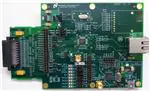
placed on J55 to bypass the regulator. In both cases, LED D2 will illuminate if a voltage is
available at J11. The following image shows the default jumper configuration.
Figure 1. Default Power Supply Connection
2.1.2 USB Interface
To supply the device using the USB interface, a jumper should be placed between pins 2 and 3 of
J12.
2.1.3 External Supply
The board can be supplied from an external supply by removing the jumper on J12 and
connecting the external 3.3 V supply directly to pin 2 of J12. Ground can be connected to one of
the GND pins on the board.
2
�
DP83640 DEMO BOARD USER GUIDE
2.2
Address Setting
The PHY address can be set by placing jumpers in J24 and J26 as indicated in Table 1. Placing
2.2k ohm resistors in R47, R49, and R50 will pull PHYAD2, PHYAD3, and PHYAD4 high allowing
for PHY addresses greater than 3. The default address is 1 (no jumpers or resistors placed).
Table 1. PHY Address Settings
PHYAD1 (J26)
Open
Open
Jumpered
Jumpered
PHYAD0 (J24)
Jumpered
Open
Jumpered
Open
PHY Address
0
1 (Default)
2
3
Figure 2. Default PHY Address Setting
3
�
DP83640 DEMO BOARD USER GUIDE
2.3
Device Register Access
2.3.1 Access MDIO Through MII
To access the device registers through the MII interface jumpers should be placed between pins
1 and 2 of J3 and J4. Figure 3 shows the default jumper settings for the MDIO/MDC access via
the MII interface.
Figure 3. Default MDIO/MDC Connection
2.3.2 Access MDIO Through USB
To access the device registers through the USB interface jumpers should be placed between pins
2 and 3 of J3 and J4.
2.3.3 Access MDIO Through Parallel Port
To access the device registers through the parallel port of the PC, the jumpers on J3 and J4 must
be removed. Figure 4 shows the connection between the parallel port and the device signals:
MDIO (J4, 2), MDC (J3, 2), and GND (J22, 1).
Figure 4. Direct Connect Cable with Line Resistors
4
�
DP83640 DEMO BOARD USER GUIDE
2.4
Clock Sources
The board can be configured to operate with either a crystal or an external oscillator.
2.4.1 Crystal (Default)
The board comes with a 25 MHz crystal for use in the MII configuration. A surface mount device
using the pads provided on the bottom side of the board can replace the through-hole part.
2.4.2 Oscillator
To use the board with a 25 MHz oscillator, remove the crystal (Y2) and resistors R22 and R25,
populate the oscillator (X1) and R27 with a 0 ohm resistor. The board will accept oscillators in
both full and half can package sizes.
For Reduced MII mode, two modes of operation are supported (RMII Master Mode and RMII
Slave Mode). For RMII Master Mode, the DP83640 internally generates the 50 MHz RMII
reference clock from the 25 MHz XTAL. For RMII Slave Mode operation, an external 50 MHz
oscillator must provide the reference to the X1 input of the DP83640. Refer to the DP83640
datasheet for details on configuring the device for RMII Master and Slave Modes.
5
�
DP83640 DEMO BOARD USER GUIDE
2.5
Straps
The DP83640 Demo Board provides a combination of jumpers and resistors to configure the
strap options for the device. The following table summarizes the straps and the default settings.
Table 2. Strap Settings
Jumper Signal Name
J23
MII_MODE
J29
RMII_MAS
J25
LED_CFG
J32
CLK_OUT_EN
J35
PCF_EN
J33
ACT
J36
SPEED
J39
LINK
R46
FX_EN_Z
PHY Address
J24
PHYAD0
J26
PHYAD1
R47
PHYAD2
R49
PHYAD3
R50
PHYAD4
IC Pin Name
RX_DV
TXD_3
CRS/CRS_DV
GPIO1
GPIO2
LED_ACT
LED_SPEED
LED_LINK
RX_ER
Function
MII Mode Select
RMII Master Enable
LED Configuration
CLK_OUT Enable
PHY Control Frame Enable
Sets Mode in Auto Negotiation
Sets Mode in Auto Negotiation
Auto-Negotiation Enable
Fiber Mode Enable
COL
RXD_3
RXD_2
RXD_1
RXD_0
PHY Address Bit 0
PHY Address Bit 1
PHY Address Bit 2
PHY Address Bit 3
PHY Address Bit 4
Default Setting
Open
Open
Open
Open
Open
High
High
High
Open
Open
Open
Open
Open
Open
Refer to the DP83640 datasheet for specific details related to each strap option. The position of
the default strap settings are indicated below for each version of the board.
Table 3. Default Strap Locations and LED Differences per Board Revision
Revision 1
Revision 2
6
Revision 3
�
DP83640 DEMO BOARD USER GUIDE
2.6
LEDs
Various LEDs are provided to assist the user in determining the state of operation of the board.
Table 4 and Table 5 clarify the relationship between the LEDs and Jumpers.
Table 4. List of LEDs with Jumpers
LED
Associated Jumper
Revision 1 Revision 2 Revision 3
D1
D2
D13
D13 / D21 D13 / D33
J42
D10
D10 / D19 D10 / D30
J39
D7
D7 / D17
D7 / D27
J36
D4
D4 / D15
D4 / D24
J33
D12
D12 / D20 D12 / D32
J41
D9
D9 / D18
D9 / D29
J38
D6
D6 / D16
D6 / D26
J35
D3
D3 / D14
D3 / D23
J32
Revision 1 and 2
Function
Interrupt Indication
MII Power Supply Indication
GPIO8
Link (GPIO7)
Speed (GPIO6)
Activity (GPIO5)
GPIO4
GPIO3
GPIO2
GPIO1
Revision 3
Table 5. LED/Jumper Order
LEDs can be used to indicate the state of GPIOs 1 through 8. When it is desired that the LED is
“ON” when the GPIO is “LOW”, the associated jumper should be set to the “UP” state. With this
setting a GREEN LED will be illuminated. When it is desired that the LED is “ON” when the GPIO
is “HIGH”, the associated jumper should be set to the “DN” state. In this case, an AMBER LED
has been incorporated in the circuit. Care should be taken when selecting the LED polarity of
the GPIO which also function as strap inputs.
7
�
DP83640 DEMO BOARD USER GUIDE
Refer to Table 3 for the “UP” and “DN” jumper position for each board revision. Note that on
Revision 2 of the board, two separate LEDs have been used.
For additional information about the functionality of pins connected to the LEDs (with the
exception of D2), refer to the DP83640 datasheet.
2.7
SMA Connectors
For convenience, two SMA connectors are provided (J2 and J34). J2 can be connected to the
CLK_OUT pin by placing a 0 ohm resistor at R1. Similarly, J34 can be connected to GPIO9 by
placing a 0 ohm resistor at R86. 50 ohm resistors can be placed at R2 and R62 to provide a
terminating impedance for test equipment, if desired.
8
�
DP83640 DEMO BOARD USER GUIDE
2.8
Table of Jumpers
Table 6. List of Jumpers
Jumper Name
Power
J11/J12
J55
MII 5V/3V3
MDIO/MDC Access
J3
MDC_SEL
J4
MDIO_SEL
J22
GND
Address
J24
PHYAD0
J26
PHYAD1
Auto-Negotiation
J33
ACT
J36
J39
Reset
J8
J40
Function
J5
J23
Function
Default
Setting
Selects device 3.3 V source (Default MII_3V3)
Bypasses 3.3 V regulator for 3.3 V MII supply
Allows selection between USB, MII or parallel port
MDC source
Allows selection between USB, MII or parallel port
MDIO source
Ground for parallel port source
PHY address strap pin
PHY address strap pin
Open
Jumper to
PMDC_MII
Jumper to
PMDIO_MII
Open
Open
Open
LINK
Force/Advertised operation mode in autonegotiation
Force/Advertised operation mode in autonegotiation
Enable/Disable auto-negotiation
RESET_N
/RESET
Allows reset of DP83640
Allows reset of USB interface device
Open
Open
PWRDOWN/INTN
MII_MODE
Allows for powerdown and interrupt modes
Allows for MII_MODE strap option. Placing the
jumper forces the unit into RMII mode.
Allows for LED configuration strap option
Allows for RMII_MAS strap option. Placing the
jumper forces the unit into RMII Master mode when
MII_MODE (J23) is strapped.
Allows GPIO1 LED connection and CLK_OUT_EN
strap option
Allows GPIO2 LED connection and PCF_EN strap
option
Allows GPIO3 LED connection
Allows GPIO4 LED connection
Allows GPIO8 LED connection
ALP EEPROM write control (Internal Use)
Open
Open
SPEED
J25
J29
LED_CFG
RMII_MAS
J32
GPIO1
J35
GPIO2
J38
J41
J42
J64
GPIO3
GPIO4
GPIO8
9
Pulled High
Pulled High
Pulled High
Open
Open
Open
Open
Open
Open
Open
Open
�
DP83640 DEMO BOARD USER GUIDE
Interface
J1
J2
J6
J7
J34
J46
J53
J56
J58
J60
2.9
GPIO Header
CLK_1588
JTAG
USB
GPIO9
Connector
FX Transceiver
MII Header
MII Male
Connector
ALP Connector
Allows access to GPIO pins
Allows access to CLK_OUT signal
JTAG interface for DP83640
USB Mini B connector
SMA Connector to GPIO9
RJ-45 connector
HP FX transceiver (AFBR5803Z) - Not stuffed in
copper configuration
Allow connection to MII pins
Smartbits Interface
Internal Use – Not placed on Customer Demo
Boards
Modification for Fiber Operation
Provisions have been made to allow for the evaluation board to be configured for fiber mode
operation. To modify the board for fiber operation, the components on Sheet 7 of the schematic
should be placed, with R113, R114, R117, R118, and R128 all 0 ohm resistors. A 2.2k ohm
resistor should also be placed in R46 to strap the device into fiber mode. Resistors R112, R115,
R116, and R119 should be removed.
2.10 Register Access Software
Access to the device registers is available with the use of National’s Analog LaunchPAD
software. Refer to the DP83640 datasheet for detailed information on specific registers and to
the National Semiconductor website (www.national.com) for the most recent version of the
Analog LaunchPAD programming software.
10
�
DP83640 DEMO BOARD USER GUIDE
2.11 Board Revision Differences
The following table highlights the differences between the board revisions.
Table 7. Board Revision Differences
Revision 1
Revision 2
Board Number:
Board Number:
551013211-001 Rev A
551013211-002 Rev A
Strap Polarity and LEDs
RESET_N
USB Power Regulator Circuit
11
Revision 3
Board Number:
551013211-003 Rev A
�IMPORTANT NOTICE
Texas Instruments Incorporated and its subsidiaries (TI) reserve the right to make corrections, modifications, enhancements, improvements,
and other changes to its products and services at any time and to discontinue any product or service without notice. Customers should
obtain the latest relevant information before placing orders and should verify that such information is current and complete. All products are
sold subject to TI’s terms and conditions of sale supplied at the time of order acknowledgment.
TI warrants performance of its hardware products to the specifications applicable at the time of sale in accordance with TI’s standard
warranty. Testing and other quality control techniques are used to the extent TI deems necessary to support this warranty. Except where
mandated by government requirements, testing of all parameters of each product is not necessarily performed.
TI assumes no liability for applications assistance or customer product design. Customers are responsible for their products and
applications using TI components. To minimize the risks associated with customer products and applications, customers should provide
adequate design and operating safeguards.
TI does not warrant or represent that any license, either express or implied, is granted under any TI patent right, copyright, mask work right,
or other TI intellectual property right relating to any combination, machine, or process in which TI products or services are used. Information
published by TI regarding third-party products or services does not constitute a license from TI to use such products or services or a
warranty or endorsement thereof. Use of such information may require a license from a third party under the patents or other intellectual
property of the third party, or a license from TI under the patents or other intellectual property of TI.
Reproduction of TI information in TI data books or data sheets is permissible only if reproduction is without alteration and is accompanied
by all associated warranties, conditions, limitations, and notices. Reproduction of this information with alteration is an unfair and deceptive
business practice. TI is not responsible or liable for such altered documentation. Information of third parties may be subject to additional
restrictions.
Resale of TI products or services with statements different from or beyond the parameters stated by TI for that product or service voids all
express and any implied warranties for the associated TI product or service and is an unfair and deceptive business practice. TI is not
responsible or liable for any such statements.
TI products are not authorized for use in safety-critical applications (such as life support) where a failure of the TI product would reasonably
be expected to cause severe personal injury or death, unless officers of the parties have executed an agreement specifically governing
such use. Buyers represent that they have all necessary expertise in the safety and regulatory ramifications of their applications, and
acknowledge and agree that they are solely responsible for all legal, regulatory and safety-related requirements concerning their products
and any use of TI products in such safety-critical applications, notwithstanding any applications-related information or support that may be
provided by TI. Further, Buyers must fully indemnify TI and its representatives against any damages arising out of the use of TI products in
such safety-critical applications.
TI products are neither designed nor intended for use in military/aerospace applications or environments unless the TI products are
specifically designated by TI as military-grade or "enhanced plastic." Only products designated by TI as military-grade meet military
specifications. Buyers acknowledge and agree that any such use of TI products which TI has not designated as military-grade is solely at
the Buyer's risk, and that they are solely responsible for compliance with all legal and regulatory requirements in connection with such use.
TI products are neither designed nor intended for use in automotive applications or environments unless the specific TI products are
designated by TI as compliant with ISO/TS 16949 requirements. Buyers acknowledge and agree that, if they use any non-designated
products in automotive applications, TI will not be responsible for any failure to meet such requirements.
Following are URLs where you can obtain information on other Texas Instruments products and application solutions:
Products
Applications
Audio
www.ti.com/audio
Automotive and Transportation www.ti.com/automotive
Amplifiers
amplifier.ti.com
Communications and Telecom www.ti.com/communications
Data Converters
dataconverter.ti.com
Computers and Peripherals
www.ti.com/computers
DLP® Products
www.dlp.com
Consumer Electronics
www.ti.com/consumer-apps
DSP
dsp.ti.com
Energy and Lighting
www.ti.com/energy
Clocks and Timers
www.ti.com/clocks
Industrial
www.ti.com/industrial
Interface
interface.ti.com
Medical
www.ti.com/medical
Logic
logic.ti.com
Security
www.ti.com/security
Power Mgmt
power.ti.com
Space, Avionics and Defense
www.ti.com/space-avionics-defense
Microcontrollers
microcontroller.ti.com
Video and Imaging
www.ti.com/video
RFID
www.ti-rfid.com
OMAP Mobile Processors
www.ti.com/omap
Wireless Connectivity
www.ti.com/wirelessconnectivity
TI E2E Community Home Page
e2e.ti.com
Mailing Address: Texas Instruments, Post Office Box 655303, Dallas, Texas 75265
Copyright © 2012, Texas Instruments Incorporated
�